EP1413471A1 - An upholstery element having a foam body, integrating a detection web - Google Patents
An upholstery element having a foam body, integrating a detection web Download PDFInfo
- Publication number
- EP1413471A1 EP1413471A1 EP03292519A EP03292519A EP1413471A1 EP 1413471 A1 EP1413471 A1 EP 1413471A1 EP 03292519 A EP03292519 A EP 03292519A EP 03292519 A EP03292519 A EP 03292519A EP 1413471 A1 EP1413471 A1 EP 1413471A1
- Authority
- EP
- European Patent Office
- Prior art keywords
- mold
- foam
- sheet
- molding cavity
- ply
- Prior art date
- Legal status (The legal status is an assumption and is not a legal conclusion. Google has not performed a legal analysis and makes no representation as to the accuracy of the status listed.)
- Withdrawn
Links
- 239000006260 foam Substances 0.000 title claims abstract description 62
- 238000001514 detection method Methods 0.000 title claims abstract description 25
- 239000000725 suspension Substances 0.000 claims abstract description 21
- 125000006850 spacer group Chemical group 0.000 claims abstract description 9
- 230000001681 protective effect Effects 0.000 claims abstract description 4
- 238000000465 moulding Methods 0.000 claims description 26
- 239000011248 coating agent Substances 0.000 claims description 16
- 238000000576 coating method Methods 0.000 claims description 16
- 238000000034 method Methods 0.000 claims description 16
- 238000012856 packing Methods 0.000 claims description 11
- 239000000203 mixture Substances 0.000 claims description 8
- 239000002243 precursor Substances 0.000 claims description 7
- 238000004519 manufacturing process Methods 0.000 claims description 5
- 238000010438 heat treatment Methods 0.000 claims description 2
- 230000035515 penetration Effects 0.000 claims 2
- 239000000463 material Substances 0.000 abstract description 8
- 241000195940 Bryophyta Species 0.000 description 4
- 235000011929 mousse Nutrition 0.000 description 4
- 239000004753 textile Substances 0.000 description 4
- 210000004027 cell Anatomy 0.000 description 3
- 238000005187 foaming Methods 0.000 description 3
- 238000011065 in-situ storage Methods 0.000 description 3
- 238000002347 injection Methods 0.000 description 3
- 239000007924 injection Substances 0.000 description 3
- 208000031968 Cadaver Diseases 0.000 description 1
- 238000004026 adhesive bonding Methods 0.000 description 1
- 230000006835 compression Effects 0.000 description 1
- 238000007906 compression Methods 0.000 description 1
- 238000011109 contamination Methods 0.000 description 1
- 230000005389 magnetism Effects 0.000 description 1
- 238000013507 mapping Methods 0.000 description 1
- 239000004033 plastic Substances 0.000 description 1
- 229920003023 plastic Polymers 0.000 description 1
- 229920002635 polyurethane Polymers 0.000 description 1
- 239000004814 polyurethane Substances 0.000 description 1
- 230000000284 resting effect Effects 0.000 description 1
- 239000000243 solution Substances 0.000 description 1
Images

Classifications
-
- B—PERFORMING OPERATIONS; TRANSPORTING
- B60—VEHICLES IN GENERAL
- B60N—SEATS SPECIALLY ADAPTED FOR VEHICLES; VEHICLE PASSENGER ACCOMMODATION NOT OTHERWISE PROVIDED FOR
- B60N2/00—Seats specially adapted for vehicles; Arrangement or mounting of seats in vehicles
- B60N2/002—Seats provided with an occupancy detection means mounted therein or thereon
- B60N2/0021—Seats provided with an occupancy detection means mounted therein or thereon characterised by the type of sensor or measurement
- B60N2/003—Seats provided with an occupancy detection means mounted therein or thereon characterised by the type of sensor or measurement characterised by the sensor mounting location in or on the seat
- B60N2/0033—Seats provided with an occupancy detection means mounted therein or thereon characterised by the type of sensor or measurement characterised by the sensor mounting location in or on the seat mounted on or in the foam cushion
-
- B—PERFORMING OPERATIONS; TRANSPORTING
- B60—VEHICLES IN GENERAL
- B60N—SEATS SPECIALLY ADAPTED FOR VEHICLES; VEHICLE PASSENGER ACCOMMODATION NOT OTHERWISE PROVIDED FOR
- B60N2210/00—Sensor types, e.g. for passenger detection systems or for controlling seats
Definitions
- the invention relates to a trim element for a motor vehicle seat, comprising a foam body provided with a coating and a ply for detecting the sinking of said element.
- the invention also relates to a mold for producing such an element, a method for producing a lining element using such a mold, and a motor vehicle seat comprising such an element.
- this ply is generally formed by a superposition of layers of plastic material, which gives it a rigidity greater than that of the foam forming the body of the element.
- the invention provides a trim element for a motor vehicle seat comprising a detection sheet disposed inside the foam body.
- This arrangement has the advantage of making it possible to achieve comfort and an appearance equivalent to those of a packing element devoid of ply, while guaranteeing effective detection.
- the positioning of the sheet inside the foam body can be determined so as to obtain an optimal detection of the occupant or of the object concerned, and this in a particularly simple manner.
- this positioning is achieved by means of a specific and modular tool, which also makes it possible to implement the so-called “in situ” molding technique for producing the lining element.
- This technique has the advantage of allowing the lining element to be obtained directly from the mold.
- the invention provides a trim element for a motor vehicle seat, comprising a foam body provided with a coating, and a ply for detecting the sinking of said element, in which the detection layer is coated in the foam body so as to be positioned inside said body at a predetermined depth.
- the invention relates to a mold for producing such a lining element, of the type comprising a tank and a cover defining between them a molding cavity when the mold is closed, said mold further comprising a device for keeping the web in suspension in the molding cavity in the X, Y and Z directions.
- the foam is injected into the molding cavity directly against the walls of the latter and the covering cap is associated with the foam body after the mold is removed from the mold.
- the invention relates to a motor vehicle seat, in which the seat and / or the backrest are formed of such a trim element.
- the trim element 1 according to the invention is intended for a motor vehicle seat, and can be arranged in the seat and / or the seat back.
- This element comprises a foam body 2, formed for example of polyurethane.
- This foam body 2 is provided with a coating, in particular textile, making it possible to give the seat a satisfactory appearance and behavior.
- This element 1 further comprises a detection ply 3 capable of providing information on the state of depression of the flexible surface of the element 1, and consequently on the possible presence of passengers or objects bearing on this surface, or, more precisely, on certain characteristics of these by mapping the detected depression.
- this sheet 3 is coated in the foam body 2, and this so as to be positioned at a predetermined depth. This depth must ensure optimal performance in terms of detection, while preserving the appearance of the seat and the comfort it provides.
- the detection layer 3 can be wrapped, within the foam, in a protective sheath.
- This sheath is to prevent possible contamination by the foam of the components present on the tablecloth.
- the presence of this sheath makes it possible to promote the sliding of the sheet, which contributes to improving its detection performance.
- the element 1 may include a heating sheet disposed near the contact surface between the element 1 and the passenger.
- the positioning of the detection ply 3 in this case has the advantage of avoiding any problem of compatibility between these two plies, the latter not being in contact with one another.
- this process is carried out by the so-called in situ molding technique.
- This technique typically consists in injecting a precursor mixture of foam into a mold whose internal wall has been previously covered at least partially with a coating.
- the method according to the invention uses a specific mold.
- this mold comprises a tank and a cover defining between them a mold cavity when the mold is closed. It further comprises a device for holding the sheet in suspension in the three directions X, Y and Z. This holding device is intended to allow the positioning of the sheet 3 in the molding cavity so that, at the outlet of mold, it is positioned at a predetermined depth in the foam body 2.
- the holding device can be integrated into the mold. However, as a variant, it may be partially or completely separable from the mold.
- a cap which forms at least part of the covering, this cap being in particular formed from a textile material.
- the cap is arranged on a part of the surface of the mold cavity formed between the tank and the mold cover.
- the cap is arranged in the mold tank, its edges being arranged on the parting line.
- the cap can be placed on the lid of the mold, and an additional step of the process can then consist in placing a layer of material on the tank, this layer of material, in particular formed of a rigid material, being intended to form another part of the coating.
- the next step consists in placing the sheet 3 on the device for holding in suspension previously fixed to the mold, so that the sheet 3 is kept in suspension in the molding cavity in the directions X, Y and Z.
- this suspension holding device is formed by two blades 4 extending parallel to the bottom of the tank, in the direction X.
- the structure and dimensions of these blades 4 are provided so that each of them can be associated with a detection layer 3, and keep it in suspension in the directions X and Y.
- the association of the blades 4 with the layers 3 is done by any means known, for example by temporary bonding, by a suction system or by magnetism.
- the two blades 4 are associated by one of their ends with a body 5 of the device, so as to allow the positioning of the sheets 3 in the direction Z, at a predetermined depth.
- FIG. 1b only one of these blades 4 with which a ply 3 is associated is visible, the second blade 4 with which the second ply 3 is associated being symmetrical relative to the center of the element 1.
- a single U-shaped sheet can be associated with the two blades 4.
- the holding device can, according to another embodiment, comprise means for positioning the ply 3 in the molding cavity in the direction Z.
- the ply 3 is associated with these positioning means by any known means.
- the positioning means along Z are directly associated with the mold cover by any known means.
- the device further comprises a support 6 intended to hold said positioning means in the molding cavity.
- the support 6 is formed of a frame extending substantially parallel to the bottom of the tank, and held by one of its ends 7 to a body 5 of the device.
- the other end 8 of the frame is more particularly intended to receive the means for positioning the sheet along Z, so as to maintain these in the molding cavity.
- the means for positioning the sheet along Z comprise associated spacers on the support 6, in the vicinity of the end part 8 formed of a cross-member.
- these spacers are formed of rods 9, shown two in number.
- rods 9 it is also possible to provide a plurality of evenly spaced rods 9 along the cross-member 8, so as to limit as much as possible the deflection of the ply 3 during the subsequent foaming step.
- the spacers are formed of truncated cones 10, the widest base of these cones 10 being associated with the cross-member 8.
- the cones 10a represented in FIGS. 3a and 3b are three in number, and are equally distributed over the entire length of the cross member 8. The presence of a central cone makes it possible to limit the deflection of the ply 3 during its coating in the foam.
- the cones 10b are two in number, and are of a height less than that of the cones 10a represented in FIGS. 3a and 3b, so as to position the ply 3 at a greater depth important in the foam body 2 relative to the user.
- these cones 10b are of larger diameter than those shown in FIGS. 3a and 3b, their diameter being designed to occupy substantially the entire width of the ply 3 when the latter is associated with them.
- the support 6 and the spacers can be integrated into the mold, or else be at least partially separable from the mold.
- the support 6 is integrated into the cover of the mold, and the spacers are separable therefrom.
- the next step in the process is the in situ foaming step, in which the foam or the foam precursor mixture is injected inside the molding cavity, said foam being intended to form the body 2 of the element. packing 1.
- the injection is carried out on the internal surface of the cap. And, when, according to another embodiment, the cap is disposed on the cover, the injection is carried out on the mold tank, or if necessary on the layer of material forming the other part of the coating.
- the packing element 1 is then molded so that the foam fills the mold cavity by coating the sheet 3 as well as its device for holding in suspension. This step is carried out after closing the mold.
- the packing element 1 integrating the detection ply 3 is then removed from the mold.
- the holding device is removed from the packing element 1, so that the latter includes areas devoid of foam corresponding to the areas where the device was before demolding.
- These areas devoid of foam located in the vicinity of the sheet allow good deformation of the sheet 3 within the foam, which, combined with an increase in compression at the periphery of said areas, improves its detection performance.
- the device is integrated into the mold, said device remains inside the mold during the demolding step, and, if at least part of the device is separable from the mold, the latter is removed from the part after release.
- the holding device according to its first embodiment namely when it is in the form of blades 4, has the consequence of leaving in the final piece areas devoid of foam having the shape of said blades.
- the blades 4 can be articulated relative to the mold, which facilitates the demolding step.
- the two other embodiments of the device induce the presence of areas devoid of foam having the shape of rods 9 or cones 10 respectively, the conical shape more particularly facilitating the demolding step.
- the shape and location of the areas devoid of foam left by the holding device are provided to respect the comfort of the seat user.
- this depth is between 10 and 30 mm from the surface of the element 1 on which the sinking must be detected, for example 20 mm , for the embodiments represented in FIGS. 1, 2 and 3, and is greater than or equal to 30 mm from this surface, for example 40 mm, for the embodiment represented in FIG. 4.
- the foam is injected directly into the molding cavity against the walls of the latter.
- the foam body 2 is thus formed which coats the detection sheet 3. After demolding this body, the covering cap is associated with it.
Landscapes
- Engineering & Computer Science (AREA)
- Aviation & Aerospace Engineering (AREA)
- Transportation (AREA)
- Mechanical Engineering (AREA)
- Casting Or Compression Moulding Of Plastics Or The Like (AREA)
Abstract
Description
L'invention concerne un élément de garnissage pour siège de véhicule automobile, comprenant un corps en mousse pourvu d'un revêtement et une nappe de détection de l'enfoncement dudit élément. L'invention concerne également un moule pour la réalisation d'un tel élément, un procédé de réalisation d'un élément de garnissage utilisant un tel moule, et un siège de véhicule automobile comprenant un tel élément.The invention relates to a trim element for a motor vehicle seat, comprising a foam body provided with a coating and a ply for detecting the sinking of said element. The invention also relates to a mold for producing such an element, a method for producing a lining element using such a mold, and a motor vehicle seat comprising such an element.
Pour déceler la présence d'un passager et certaines de ses caractéristiques physiques, la présence d'un dispositif de retenue pour enfant ou de tout autre objet en appui sur la surface du siège, il est connu de prévoir une nappe de détection sur la surface d'au moins un élément de garnissage du siège, notamment l'assise.To detect the presence of a passenger and some of its physical characteristics, the presence of a child restraint or any other object resting on the surface of the seat, it is known to provide a detection sheet on the surface at least one seat upholstery element, in particular the seat.
On connaît déjà des éléments de garnissage comprenant de telles nappes, ces nappes étant disposées entre le revêtement et le corps en mousse, de sorte à être proches de la zone de contact entre l'élément et l'occupant ou l'objet à détecter. Ce positionnement de la nappe favorise l'efficacité de la détection, mais présente des inconvénients.There are already known packing elements comprising such plies, these plies being disposed between the covering and the foam body, so as to be close to the contact zone between the element and the occupant or the object to be detected. This positioning of the sheet promotes the effectiveness of detection, but has drawbacks.
En particulier, cette nappe est généralement formée d'une superposition de couches de matière plastique, ce qui lui confère une rigidité supérieure à celle de la mousse formant le corps de l'élément.In particular, this ply is generally formed by a superposition of layers of plastic material, which gives it a rigidity greater than that of the foam forming the body of the element.
Or, la présence d'une nappe rigide à proximité d'un passager rend le siège peu confortable. En outre, le fait que la nappe rigide soit en contact direct avec le revêtement textile induit des problèmes d'aspect.However, the presence of a rigid sheet near a passenger makes the seat uncomfortable. In addition, the fact that the rigid ply is in direct contact with the textile covering induces appearance problems.
Pour améliorer le confort et l'aspect de tels sièges, il a été proposé d'utiliser un revêtement textile d'épaisseur plus importante, ou de disposer entre la nappe et le revêtement une couche de mousse spécifique. Toutefois, dans ce cas, la mise en place de la nappe s'effectue par collage, ce qui peut entraîner une mauvaise tenue de la nappe au cours du temps. En outre, les deux solutions proposées impliquent un surcoût important.To improve the comfort and appearance of such seats, it has been proposed to use a textile covering of greater thickness, or to have a layer of specific foam between the sheet and the covering. However, in this case, the ply is put in place by gluing, which can lead to poor performance of the ply over time. In addition, the two solutions proposed involve a significant additional cost.
Afin de remédier à ces inconvénients, l'invention propose un élément de garnissage pour siège de véhicule automobile comprenant une nappe de détection disposée à l'intérieur du corps en mousse.In order to remedy these drawbacks, the invention provides a trim element for a motor vehicle seat comprising a detection sheet disposed inside the foam body.
Cet agencement présente l'avantage de permettre d'atteindre un confort et un aspect équivalents à ceux d'un élément de garnissage dépourvu de nappe, tout en garantissant une détection efficace. En outre, suivant l'invention, le positionnement de la nappe à l'intérieur du corps en mousse peut être déterminé de sorte à obtenir une détection optimale de l'occupant ou de l'objet concerné, et ce de façon particulièrement simple.This arrangement has the advantage of making it possible to achieve comfort and an appearance equivalent to those of a packing element devoid of ply, while guaranteeing effective detection. In addition, according to the invention, the positioning of the sheet inside the foam body can be determined so as to obtain an optimal detection of the occupant or of the object concerned, and this in a particularly simple manner.
En effet, ce positionnement est réalisé grâce à un outillage spécifique et modulable, qui permet en outre de mettre en oeuvre la technique de moulage dite « in situ » pour la réalisation de l'élément de garnissage. Cette technique présente l'avantage de permettre l'obtention directe de l'élément de garnissage en sortie de moule.In fact, this positioning is achieved by means of a specific and modular tool, which also makes it possible to implement the so-called "in situ" molding technique for producing the lining element. This technique has the advantage of allowing the lining element to be obtained directly from the mold.
A cet effet, et selon un premier aspect, l'invention propose un élément de garnissage pour siège de véhicule automobile, comprenant un corps en mousse pourvu d'un revêtement, et une nappe de détection de l'enfoncement dudit élément, dans lequel la nappe de détection est enrobée dans le corps en mousse de sorte à être positionnée à l'intérieur dudit corps à une profondeur prédéterminée.To this end, and according to a first aspect, the invention provides a trim element for a motor vehicle seat, comprising a foam body provided with a coating, and a ply for detecting the sinking of said element, in which the detection layer is coated in the foam body so as to be positioned inside said body at a predetermined depth.
De plus, le fait d'enrober la nappe dans la mousse permet de s'affranchir d'éventuels problèmes de tenue au cours du temps.In addition, the fact of coating the sheet in the foam makes it possible to overcome any problems of resistance over time.
Selon un deuxième aspect, l'invention concerne un moule pour la réalisation d'un tel élément de garnissage, du type comprenant une cuve et un couvercle définissant entre eux une cavité de moulage lorsque le moule est fermé, ledit moule comprenant en outre un dispositif de maintien en suspension de la nappe dans la cavité de moulage suivant les directions X, Y et Z.According to a second aspect, the invention relates to a mold for producing such a lining element, of the type comprising a tank and a cover defining between them a molding cavity when the mold is closed, said mold further comprising a device for keeping the web in suspension in the molding cavity in the X, Y and Z directions.
Selon un troisième aspect, l'invention concerne un procédé de réalisation d'un tel élément de garnissage, utilisant un tel moule, ledit procédé comprenant les étapes successives suivantes :
- associer la nappe au dispositif de maintien en suspension, de sorte que la nappe soit maintenue en suspension dans la cavité de moulage suivant les directions X, Y et Z ;
- injecter une mousse ou un mélange précurseur de mousse à l'intérieur de la cavité de moulage ;
- mouler ledit élément de sorte que la mousse remplisse la cavité de moulage en venant enrober la nappe ;
- démouler ledit élément intégrant la nappe, de sorte à laisser dans le corps des zones dépourvues de mousse.
- associating the ply with the device for holding in suspension, so that the ply is kept in suspension in the molding cavity in the directions X, Y and Z;
- injecting a foam or a foam precursor mixture inside the mold cavity;
- molding said element so that the foam fills the molding cavity by coating the sheet;
- unmold said element incorporating the sheet, so as to leave zones in the body devoid of foam.
Selon une première variante du procédé, on prévoit de disposer une coiffe formant revêtement dans la cavité de moulage, préalablement à l'injection de la mousse.According to a first variant of the method, provision is made to have a cap forming a coating in the molding cavity, prior to the injection of the foam.
Selon une deuxième variante, la mousse est injectée dans la cavité de moulage directement contre les parois de celle-ci et on associe la coiffe formant revêtement au corps en mousse après le démoulage de celui-ci.According to a second variant, the foam is injected into the molding cavity directly against the walls of the latter and the covering cap is associated with the foam body after the mold is removed from the mold.
Selon un quatrième aspect, l'invention concerne un siège de véhicule automobile, dans lequel l'assise et/ou le dossier sont formés d'un tel élément de garnissage.According to a fourth aspect, the invention relates to a motor vehicle seat, in which the seat and / or the backrest are formed of such a trim element.
D'autres objets et avantages de l'invention apparaîtront au cours de la description qui suit, faite en référence aux dessins annexés dans lesquels :
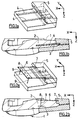
- les figures 1 a et 1b sont respectivement une vue schématique en perspective d'un dispositif de maintien en suspension de la nappe selon un premier mode de réalisation, et une vue en coupe transversale d'un élément de garnissage et dudit dispositif après moussage ;
- les figures 2a et 2b sont des vues analogues à celles de la figure 1, montrant le dispositif de maintien selon un deuxième mode de réalisation ;
- les figures 3a et 3b sont des vues analogues à celles de la figure 1, montrant le dispositif de maintien selon un troisième mode de réalisation ;
- les figures 4a et 4b sont des vues analogues à celles de la figure 1, montrant le dispositif de maintien selon une variante du troisième mode de réalisation.
- Figures 1a and 1b are respectively a schematic perspective view of a device for holding the web in suspension according to a first embodiment, and a cross-sectional view of a packing element and of said device after foaming;
- Figures 2a and 2b are views similar to those of Figure 1, showing the holding device according to a second embodiment;
- Figures 3a and 3b are views similar to those of Figure 1, showing the holding device according to a third embodiment;
- Figures 4a and 4b are views similar to those of Figure 1, showing the holding device according to a variant of the third embodiment.
L'élément de garnissage 1 selon l'invention est destiné à un siège de véhicule automobile, et peut être disposé dans l'assise et/ou le dossier du siège.The trim element 1 according to the invention is intended for a motor vehicle seat, and can be arranged in the seat and / or the seat back.
Cet élément comprend un corps en mousse 2, formé par exemple de polyuréthanne. Ce corps en mousse 2 est pourvu d'un revêtement, notamment textile, permettant de conférer au siège un aspect et une tenue satisfaisantes.This element comprises a
Cet élément 1 comprend en outre une nappe de détection 3 apte à fournir des informations sur l'état d'enfoncement de la surface flexible de l'élément 1, et par conséquent sur la présence éventuelle de passagers ou d'objets en appui sur cette surface, ou bien, de façon plus précise, sur certaines caractéristiques de ceux-ci par cartographie de l'enfoncement détecté.This element 1 further comprises a
Selon l'invention, cette nappe 3 est enrobée dans le corps en mousse 2, et ce de sorte à être positionnée à une profondeur prédéterminée. Cette profondeur doit permettre d'assurer une performance optimale en terme de détection, tout en préservant l'aspect du siège et le confort conféré par celui-ci.According to the invention, this
Selon une réalisation, la nappe de détection 3 peut être enveloppée, au sein de la mousse, dans un fourreau de protection. Ce fourreau a pour fonction d'éviter une éventuelle contamination par la mousse des composants présents sur la nappe. En outre, la présence de ce fourreau permet de favoriser le glissement de la nappe, ce qui contribue à améliorer ses performances de détection.According to one embodiment, the
En outre, l'élément 1 peut comprendre une nappe chauffante disposée à proximité de la surface de contact entre l'élément 1 et le passager. Le positionnement de la nappe de détection 3 présente dans ce cas l'avantage d'éviter toute problème de compatibilité entre ces deux nappes, celles-ci n'étant pas en contact l'une avec l'autre.In addition, the element 1 may include a heating sheet disposed near the contact surface between the element 1 and the passenger. The positioning of the
On décrit à présent le procédé de réalisation de l'élément de garnissage 1.We now describe the process for producing the packing element 1.
Selon une première variante, ce procédé est réalisé par la technique de moulage dite in situ.According to a first variant, this process is carried out by the so-called in situ molding technique.
Cette technique consiste typiquement à injecter un mélange précurseur de mousse dans un moule dont la paroi interne a été au préalable recouverte au moins partiellement d'un revêtement.This technique typically consists in injecting a precursor mixture of foam into a mold whose internal wall has been previously covered at least partially with a coating.
Le procédé selon l'invention utilise un moule spécifique. De façon connue, ce moule comprend une cuve et un couvercle définissant entre eux une cavité de moulage lorsque le moule est fermé. Il comprend en outre un dispositif de maintien en suspension de la nappe dans les trois directions X, Y et Z. Ce dispositif de maintien est destiné à permettre le positionnement de la nappe 3 dans la cavité de moulage de façon telle que, en sortie de moule, celle-ci soit positionnée à une profondeur prédéterminée dans le corps en mousse 2.The method according to the invention uses a specific mold. In known manner, this mold comprises a tank and a cover defining between them a mold cavity when the mold is closed. It further comprises a device for holding the sheet in suspension in the three directions X, Y and Z. This holding device is intended to allow the positioning of the
Le dispositif de maintien peut être intégré au moule. Toutefois, en variante, il peut être partiellement ou totalement dissociable du moule.The holding device can be integrated into the mold. However, as a variant, it may be partially or completely separable from the mold.
Dans une première étape du procédé, on prévoit une coiffe formant au moins une partie du revêtement, cette coiffe étant notamment formée d'un matériau textile.In a first step of the process, a cap is provided which forms at least part of the covering, this cap being in particular formed from a textile material.
Puis la coiffe est disposée sur une partie de la surface de la cavité de moulage formée entre la cuve et le couvercle du moule. Selon une réalisation, la coiffe est disposée dans la cuve du moule, ses bords étant disposés sur le plan de joint.Then the cap is arranged on a part of the surface of the mold cavity formed between the tank and the mold cover. According to one embodiment, the cap is arranged in the mold tank, its edges being arranged on the parting line.
Selon une autre réalisation, la coiffe peut être disposée sur le couvercle du moule, et une étape supplémentaire du procédé peut alors consister à disposer une couche de matériau sur la cuve, cette couche de matériau, notamment formée d'un matériau rigide, étant destinée à former une autre partie du revêtement.According to another embodiment, the cap can be placed on the lid of the mold, and an additional step of the process can then consist in placing a layer of material on the tank, this layer of material, in particular formed of a rigid material, being intended to form another part of the coating.
L'étape suivante consiste à disposer la nappe 3 sur le dispositif de maintien en suspension préalablement fixé au moule, de sorte que la nappe 3 soit maintenue en suspension dans la cavité de moulage suivant les directions X, Y et Z.The next step consists in placing the
Selon un premier mode de réalisation, représenté sur les figures 1 a et 1b, ce dispositif de maintien en suspension est formé de deux lames 4 s'étendant parallèlement au fond de la cuve, suivant la direction X. La structure et les dimensions de ces lames 4 sont prévues pour que chacune d'entre elles puisse être associée à une nappe de détection 3, et maintenir celle-ci en suspension suivant les directions X et Y. L'association des lames 4 avec les nappes 3 se fait par tous moyens connus, par exemple par collage temporaire, par un système d'aspiration ou par magnétisme.According to a first embodiment, shown in Figures 1a and 1b, this suspension holding device is formed by two blades 4 extending parallel to the bottom of the tank, in the direction X. The structure and dimensions of these blades 4 are provided so that each of them can be associated with a
En outre, les deux lames 4 sont associées par l'une de leurs extrémités à un corps 5 du dispositif, de sorte à permettre le positionnement des nappes 3 suivant la direction Z, à une profondeur prédéterminée. Sur la figure 1b, seule l'une de ces lames 4 à laquelle est associée une nappe 3 est visible, la deuxième lame 4 à laquelle est associée la deuxième nappe 3 étant symétrique par rapport au centre de l'élément 1.In addition, the two blades 4 are associated by one of their ends with a
En variante, une seule nappe en forme de U peut être associée aux deux lames 4.As a variant, a single U-shaped sheet can be associated with the two blades 4.
Le dispositif de maintien peut, selon une autre réalisation, comprendre des moyens de positionnement de la nappe 3 dans la cavité de moulage suivant la direction Z. La nappe 3 est associée à ces moyens de positionnement par tous moyens connus.The holding device can, according to another embodiment, comprise means for positioning the
Selon une première variante de cette réalisation, les moyens de positionnement suivant Z sont directement associés au couvercle du moule par tous moyens connus.According to a first variant of this embodiment, the positioning means along Z are directly associated with the mold cover by any known means.
Selon une deuxième variante de cette réalisation, le dispositif comprend en outre un support 6 destiné à maintenir lesdits moyens de positionnement dans la cavité de moulage. Les deux modes de réalisation décrits à présent, en relation avec les figures 2 à 4, illustrent cette variante.According to a second variant of this embodiment, the device further comprises a
Le support 6 est formé d'un cadre s'étendant sensiblement parallèlement au fond de la cuve, et maintenu par l'une de ses extrémités 7 à un corps 5 du dispositif. L'autre extrémité 8 du cadre est plus particulièrement prévue pour recevoir les moyens de positionnement de la nappe suivant Z, de sorte à maintenir ceux-ci dans la cavité de moulage.The
Les moyens de positionnement de la nappe suivant Z comprennent des espaceurs associés sur le support 6, au voisinage de la partie extrême 8 formée d'une traverse.The means for positioning the sheet along Z comprise associated spacers on the
Selon le mode de réalisation représenté sur les figures 2, ces espaceurs sont formés de tiges 9, représentées au nombre de deux. Toutefois, on peut également prévoir une pluralité de tiges 9 équiréparties le long de la traverse 8, de sorte à limiter au maximum le fléchissement de la nappe 3 lors de l'étape ultérieure de moussage.According to the embodiment shown in Figures 2, these spacers are formed of
Selon le mode de réalisation du dispositif de maintien représenté sur les figures 3 et 4, les espaceurs sont formés de cônes tronqués 10, la base la plus large de ces cônes 10 étant associée à la traverse 8.According to the embodiment of the holding device shown in FIGS. 3 and 4, the spacers are formed of truncated cones 10, the widest base of these cones 10 being associated with the
Les cônes 10a représentés sur les figures 3a et 3b sont au nombre de trois, et sont équirépartis sur toute la longueur de la traverse 8. La présence d'un cône central permet de limiter le fléchissement de la nappe 3 lors de son enrobage dans la mousse.The
Selon une variante, représentée sur les figures 4a et 4b, les cônes 10b sont au nombre de deux, et sont de hauteur inférieure à celle des cônes 10a représentés sur les figures 3a et 3b, de sorte à positionner la nappe 3 à une profondeur plus importante dans le corps en mousse 2 par rapport à l'utilisateur. En outre, ces cônes 10b sont de diamètre plus large que ceux représentés sur les figures 3a et 3b, leur diamètre étant prévu pour occuper sensiblement toute la largeur de la nappe 3 lorsque celle-ci leur est associée.According to a variant, represented in FIGS. 4a and 4b, the
Le support 6 et les espaceurs peuvent être intégrés au moule, ou bien être au moins partiellement dissociables du moule. Dans un exemple particulier, le support 6 est intégré au couvercle du moule, et les espaceurs en sont dissociables.The
L'étape suivante du procédé est l'étape de moussage in situ, dans laquelle on injecte la mousse ou le mélange précurseur de mousse à l'intérieur de la cavité de moulage, ladite mousse étant destinée à former le corps 2 de l'élément de garnissage 1.The next step in the process is the in situ foaming step, in which the foam or the foam precursor mixture is injected inside the molding cavity, said foam being intended to form the
Dans le cas où la coiffe est disposée sur la cuve du moule, l'injection est réalisée sur la surface interne de la coiffe. Et, lorsque, suivant une autre réalisation, la coiffe est disposée sur le couvercle, l'injection est réalisée sur la cuve du moule, ou le cas échéant sur la couche de matériau formant l'autre partie du revêtement.In the case where the cap is placed on the mold tank, the injection is carried out on the internal surface of the cap. And, when, according to another embodiment, the cap is disposed on the cover, the injection is carried out on the mold tank, or if necessary on the layer of material forming the other part of the coating.
L'élément de garnissage 1 est alors moulé de sorte que la mousse remplisse la cavité de moulage en venant enrober la nappe 3 ainsi que son dispositif de maintien en suspension. Cette étape s'effectue après fermeture du moule.The packing element 1 is then molded so that the foam fills the mold cavity by coating the
L'élément de garnissage 1 intégrant la nappe de détection 3 est ensuite démoulé. Lors du démoulage, il est prévu que le dispositif de maintien soit retiré de l'élément de garnissage 1, de sorte que ce dernier comprenne des zones dépourvues de mousse correspondant aux zones où se trouvait le dispositif avant démoulage. Ces zones dépourvues de mousse situées au voisinage de la nappe permettent une bonne déformation de la nappe 3 au sein de la mousse, ce qui, combiné à une augmentation de la compression au niveau de la périphérie desdites zones, améliore ses performances de détection.The packing element 1 integrating the
Ainsi, si le dispositif est intégré au moule, ledit dispositif demeure à l'intérieur du moule lors de l'étape de démoulage, et, si au moins une partie du dispositif est dissociable du moule, celle-ci est retirée de la pièce après démoulage.Thus, if the device is integrated into the mold, said device remains inside the mold during the demolding step, and, if at least part of the device is separable from the mold, the latter is removed from the part after release.
L'utilisation du dispositif de maintien selon son premier mode de réalisation, à savoir lorsqu'il se présente sous forme de lames 4, a pour conséquence de laisser dans la pièce finale des zones dépourvues de mousse ayant la forme desdites lames. En outre, selon un exemple de réalisation, les lames 4 peuvent être articulées par rapport au moule, ce qui facilite l'étape de démoulage.The use of the holding device according to its first embodiment, namely when it is in the form of blades 4, has the consequence of leaving in the final piece areas devoid of foam having the shape of said blades. In addition, according to an exemplary embodiment, the blades 4 can be articulated relative to the mold, which facilitates the demolding step.
Les deux autres modes de réalisation du dispositif induisent la présence de zones dépourvues de mousse ayant la forme respectivement des tiges 9 ou des cônes 10, la forme conique facilitant plus particulièrement l'étape de démoulage.The two other embodiments of the device induce the presence of areas devoid of foam having the shape of
En particulier, lorsque le dispositif est sous sa forme représentée sur les figures 4a et 4b, les orifices présents dans la mousse, à la suite du retrait des cônes 10b, sont de diamètre important. Cet arrangement présente l'avantage de favoriser la déformation de la nappe 3, et par conséquent ses performances en terme de détection, et ce avec une nappe 3 située à une profondeur telle que le confort et l'aspect du siège s'en trouvent améliorés.In particular, when the device is in the form shown in FIGS. 4a and 4b, the orifices present in the foam, following the withdrawal of the
Quel que soit le mode de réalisation utilisé, la forme et l'emplacement des zones dépourvues de mousse laissées par le dispositif de maintien sont prévus pour respecter le confort de l'utilisateur du siège.Whatever the embodiment used, the shape and location of the areas devoid of foam left by the holding device are provided to respect the comfort of the seat user.
Après démoulage, la nappe 3 est placée, dans l'élément 1, à une profondeur donnée : cette profondeur est comprise entre 10 et 30 mm de la surface de l'élément 1 sur laquelle l'enfoncement doit être détecté, par exemple 20 mm, pour les modes de réalisation représentés sur les figures 1, 2 et 3, et est supérieure ou égale à 30 mm de cette surface, par exemple 40 mm, pour le mode de réalisation représenté sur la figure 4.After release from the mold, the
Selon une deuxième variante du procédé de réalisation de l'élément 1, on injecte directement la mousse dans la cavité de moulage contre les parois de celle-ci. On forme ainsi le corps en mousse 2 qui enrobe la nappe de détection 3. Après démoulage de ce corps, on lui associe la coiffe formant revêtement.According to a second variant of the method for producing the element 1, the foam is injected directly into the molding cavity against the walls of the latter. The
Claims (19)
Applications Claiming Priority (2)
| Application Number | Priority Date | Filing Date | Title |
|---|---|---|---|
| FR0212733 | 2002-10-14 | ||
| FR0212733A FR2845650B1 (en) | 2002-10-14 | 2002-10-14 | PACKING ELEMENT COMPRISING A FOAM BODY INCORPORATING A DETECTION TABLE |
Publications (1)
| Publication Number | Publication Date |
|---|---|
| EP1413471A1 true EP1413471A1 (en) | 2004-04-28 |
Family
ID=32039695
Family Applications (1)
| Application Number | Title | Priority Date | Filing Date |
|---|---|---|---|
| EP03292519A Withdrawn EP1413471A1 (en) | 2002-10-14 | 2003-10-10 | An upholstery element having a foam body, integrating a detection web |
Country Status (2)
| Country | Link |
|---|---|
| EP (1) | EP1413471A1 (en) |
| FR (1) | FR2845650B1 (en) |
Cited By (4)
| Publication number | Priority date | Publication date | Assignee | Title |
|---|---|---|---|---|
| EP1712403A1 (en) * | 2005-04-12 | 2006-10-18 | IEE INTERNATIONAL ELECTRONICS & ENGINEERING S.A. | Method for fitting a seat sensor into a seat cushion |
| EP2243659A1 (en) | 2009-04-22 | 2010-10-27 | IEE International Electronics & Engineering S.A. | Foam element production method |
| US20180072196A1 (en) * | 2016-09-09 | 2018-03-15 | Faurecia Sieges D'automobile | Integration of a device in a motor vehicle seat element |
| FR3059265A1 (en) * | 2016-11-30 | 2018-06-01 | Faurecia Sieges D'automobile | METHOD FOR MANUFACTURING A VEHICLE SEAT ELEMENT |
Citations (8)
| Publication number | Priority date | Publication date | Assignee | Title |
|---|---|---|---|---|
| DE19646480A1 (en) * | 1996-11-11 | 1998-05-14 | Karl Schweizer | Automobile seat squab with seat occupation sensor |
| DE19752976A1 (en) * | 1996-11-29 | 1998-06-04 | Aisin Seiki | Vehicle seat occupancy detector |
| WO1998041424A1 (en) * | 1997-03-18 | 1998-09-24 | Southwest Research Institute | Weight sensor for controlling airbag deployment |
| US5851026A (en) * | 1994-10-17 | 1998-12-22 | I.E.E. International Electronics & Engineering | Method and installation for detecting certain parameters concerning an auxiliary child seat with a view to controlling the operation of the airbags of a vehicle |
| EP0893300A2 (en) * | 1997-07-24 | 1999-01-27 | Bridgestone Corporation | Seat with seat sensor |
| US6000717A (en) * | 1998-01-15 | 1999-12-14 | Trw Inc. | Vehicle occupant protection apparatus |
| US20020067064A1 (en) * | 2000-10-31 | 2002-06-06 | Laurent Jaillet | Padded element for a vehicle, and a method of manufacturing it |
| EP1245433A2 (en) * | 2001-03-26 | 2002-10-02 | Delphi Technologies, Inc. | Seat occupant weight detection system having compensation for seat aging and usage |
-
2002
- 2002-10-14 FR FR0212733A patent/FR2845650B1/en not_active Expired - Fee Related
-
2003
- 2003-10-10 EP EP03292519A patent/EP1413471A1/en not_active Withdrawn
Patent Citations (8)
| Publication number | Priority date | Publication date | Assignee | Title |
|---|---|---|---|---|
| US5851026A (en) * | 1994-10-17 | 1998-12-22 | I.E.E. International Electronics & Engineering | Method and installation for detecting certain parameters concerning an auxiliary child seat with a view to controlling the operation of the airbags of a vehicle |
| DE19646480A1 (en) * | 1996-11-11 | 1998-05-14 | Karl Schweizer | Automobile seat squab with seat occupation sensor |
| DE19752976A1 (en) * | 1996-11-29 | 1998-06-04 | Aisin Seiki | Vehicle seat occupancy detector |
| WO1998041424A1 (en) * | 1997-03-18 | 1998-09-24 | Southwest Research Institute | Weight sensor for controlling airbag deployment |
| EP0893300A2 (en) * | 1997-07-24 | 1999-01-27 | Bridgestone Corporation | Seat with seat sensor |
| US6000717A (en) * | 1998-01-15 | 1999-12-14 | Trw Inc. | Vehicle occupant protection apparatus |
| US20020067064A1 (en) * | 2000-10-31 | 2002-06-06 | Laurent Jaillet | Padded element for a vehicle, and a method of manufacturing it |
| EP1245433A2 (en) * | 2001-03-26 | 2002-10-02 | Delphi Technologies, Inc. | Seat occupant weight detection system having compensation for seat aging and usage |
Cited By (8)
| Publication number | Priority date | Publication date | Assignee | Title |
|---|---|---|---|---|
| EP1712403A1 (en) * | 2005-04-12 | 2006-10-18 | IEE INTERNATIONAL ELECTRONICS & ENGINEERING S.A. | Method for fitting a seat sensor into a seat cushion |
| WO2006108859A1 (en) * | 2005-04-12 | 2006-10-19 | Iee International Electronics & Engineering S.A. | Method for fitting a seat sensor into a seat cushion |
| EP2243659A1 (en) | 2009-04-22 | 2010-10-27 | IEE International Electronics & Engineering S.A. | Foam element production method |
| WO2010121996A1 (en) | 2009-04-22 | 2010-10-28 | Iee International Electronics & Engineering S.A. | Foam element production method |
| US20180072196A1 (en) * | 2016-09-09 | 2018-03-15 | Faurecia Sieges D'automobile | Integration of a device in a motor vehicle seat element |
| CN108297763A (en) * | 2016-09-09 | 2018-07-20 | 富尔夏汽车座椅股份有限公司 | Device is integrated in automobile seat element |
| CN108297763B (en) * | 2016-09-09 | 2021-07-06 | 富尔夏汽车座椅股份有限公司 | Integration of a device in a motor vehicle seat element |
| FR3059265A1 (en) * | 2016-11-30 | 2018-06-01 | Faurecia Sieges D'automobile | METHOD FOR MANUFACTURING A VEHICLE SEAT ELEMENT |
Also Published As
| Publication number | Publication date |
|---|---|
| FR2845650B1 (en) | 2006-01-13 |
| FR2845650A1 (en) | 2004-04-16 |
Similar Documents
| Publication | Publication Date | Title |
|---|---|---|
| EP1118443B1 (en) | Insert for overmoulding and overmoulding process | |
| FR2815901A1 (en) | Padded component for vehicle interior e.g. seat has covering layers of supple materials distinct from foam padding | |
| EP2768699B1 (en) | Vehicle foot-rest | |
| EP1325838A1 (en) | Seat made of foam with removable cover, especially for automotive vehicle | |
| FR2942423A1 (en) | Trim cushioning forming method for seat element e.g. backrest, of motor vehicle, involves injecting polyurethane foam into casting mold, and closing casting mold during polymerization of polyurethane foam to form lower foam layer | |
| EP1413471A1 (en) | An upholstery element having a foam body, integrating a detection web | |
| FR2790232A1 (en) | Head rest for seats of vehicles | |
| FR2761863A1 (en) | Self-fastening strip for fixing foam seat padding to seat cover | |
| EP1008317A1 (en) | Seat cushion, in particular for motor vehicle, and process for its manufacture | |
| EP3641597B1 (en) | Seat | |
| EP1386711B1 (en) | Method of making an article with a soft insert | |
| FR3106791A1 (en) | Anti-submarining device for vehicle | |
| FR2866151A1 (en) | Seat occupant presence sensor for motor vehicle, has flexible units adapted so that conducting portions contact due to external pressure to circulate current, and opening to access internal space between inner sides of units from outside | |
| FR2818187A1 (en) | Motor vehicle seat component made by injecting two layers of foam after positioning front and back covering layers in mould | |
| FR2848930A1 (en) | Car seat cushion comprises pad of synthetic foam whose edges are thinner than its center, semi-rigid plate being embedded in base of the pad and attached to support strip, around which foam is expanded | |
| FR2993520A1 (en) | Lining component i.e. folding armrest, for seat of automobile, has anchoring element in form of blank including porous layer, where anchoring element is molded by block, and foam impregnating porous layer so as to rigidify porous layer | |
| EP1582116A1 (en) | Manufacturing process of a padding having a leather overlay | |
| EP0693354B1 (en) | Improvements in methods and machines for moulding composite foam upholstery | |
| FR2841509A1 (en) | Decorative trim for an automobile seating, as the seat and/or backrest, has a foam body and a textile covering, with an embedded suspension fitting for attachment to the seat frame | |
| FR3125762A1 (en) | Vehicle seat back and associated method of production | |
| FR2919238A1 (en) | Upholstery element i.e. headrest, for seat of motor vehicle, has carcass associated to support block, where external surface of support block includes small zone forming visible surface | |
| FR2621284A1 (en) | Headrest for vehicle seats, particularly for motor vehicles | |
| FR3078297A1 (en) | MOTOR VEHICLE INTERIOR EQUIPMENT PIECE, VEHICLE AND MANUFACTURING METHOD THEREOF | |
| WO2023052539A1 (en) | Element for covering a seat support element | |
| FR3140318A1 (en) | Trim for vehicle seat element and method for producing such a trim |
Legal Events
| Date | Code | Title | Description |
|---|---|---|---|
| PUAI | Public reference made under article 153(3) epc to a published international application that has entered the european phase |
Free format text: ORIGINAL CODE: 0009012 |
|
| AK | Designated contracting states |
Kind code of ref document: A1 Designated state(s): AT BE BG CH CY CZ DE DK EE ES FI FR GB GR HU IE IT LI LU MC NL PT RO SE SI SK TR |
|
| AX | Request for extension of the european patent |
Extension state: AL LT LV MK |
|
| 17P | Request for examination filed |
Effective date: 20041020 |
|
| AKX | Designation fees paid |
Designated state(s): AT BE BG CH CY CZ DE DK EE ES FI FR GB GR HU IE IT LI LU MC NL PT RO SE SI SK TR |
|
| STAA | Information on the status of an ep patent application or granted ep patent |
Free format text: STATUS: THE APPLICATION IS DEEMED TO BE WITHDRAWN |
|
| 18D | Application deemed to be withdrawn |
Effective date: 20060501 |