EP0893300A2 - Seat with seat sensor - Google Patents
Seat with seat sensor Download PDFInfo
- Publication number
- EP0893300A2 EP0893300A2 EP98305880A EP98305880A EP0893300A2 EP 0893300 A2 EP0893300 A2 EP 0893300A2 EP 98305880 A EP98305880 A EP 98305880A EP 98305880 A EP98305880 A EP 98305880A EP 0893300 A2 EP0893300 A2 EP 0893300A2
- Authority
- EP
- European Patent Office
- Prior art keywords
- seat
- sensor
- cavity
- pad
- slab
- Prior art date
- Legal status (The legal status is an assumption and is not a legal conclusion. Google has not performed a legal analysis and makes no representation as to the accuracy of the status listed.)
- Granted
Links
- 238000004519 manufacturing process Methods 0.000 abstract description 6
- 239000007779 soft material Substances 0.000 abstract description 2
- 229920005830 Polyurethane Foam Polymers 0.000 description 2
- 238000010030 laminating Methods 0.000 description 2
- 239000000463 material Substances 0.000 description 2
- -1 polypropylene Polymers 0.000 description 2
- 239000011496 polyurethane foam Substances 0.000 description 2
- 239000004698 Polyethylene Substances 0.000 description 1
- 239000004743 Polypropylene Substances 0.000 description 1
- 239000004793 Polystyrene Substances 0.000 description 1
- 239000000853 adhesive Substances 0.000 description 1
- 239000002390 adhesive tape Substances 0.000 description 1
- 239000000835 fiber Substances 0.000 description 1
- 239000010985 leather Substances 0.000 description 1
- 230000007257 malfunction Effects 0.000 description 1
- 229920000573 polyethylene Polymers 0.000 description 1
- 229920001155 polypropylene Polymers 0.000 description 1
- 229920002223 polystyrene Polymers 0.000 description 1
- 239000004800 polyvinyl chloride Substances 0.000 description 1
- 229920000915 polyvinyl chloride Polymers 0.000 description 1
- 239000011347 resin Substances 0.000 description 1
- 229920005989 resin Polymers 0.000 description 1
- 229920001169 thermoplastic Polymers 0.000 description 1
- 239000004416 thermosoftening plastic Substances 0.000 description 1
Images


Classifications
-
- A—HUMAN NECESSITIES
- A47—FURNITURE; DOMESTIC ARTICLES OR APPLIANCES; COFFEE MILLS; SPICE MILLS; SUCTION CLEANERS IN GENERAL
- A47C—CHAIRS; SOFAS; BEDS
- A47C31/00—Details or accessories for chairs, beds, or the like, not provided for in other groups of this subclass, e.g. upholstery fasteners, mattress protectors, stretching devices for mattress nets
- A47C31/12—Means, e.g. measuring means for adapting chairs, beds or mattresses to the shape or weight of persons
- A47C31/126—Means, e.g. measuring means for adapting chairs, beds or mattresses to the shape or weight of persons for chairs
-
- B—PERFORMING OPERATIONS; TRANSPORTING
- B60—VEHICLES IN GENERAL
- B60N—SEATS SPECIALLY ADAPTED FOR VEHICLES; VEHICLE PASSENGER ACCOMMODATION NOT OTHERWISE PROVIDED FOR
- B60N2/00—Seats specially adapted for vehicles; Arrangement or mounting of seats in vehicles
- B60N2/002—Seats provided with an occupancy detection means mounted therein or thereon
-
- B—PERFORMING OPERATIONS; TRANSPORTING
- B60—VEHICLES IN GENERAL
- B60N—SEATS SPECIALLY ADAPTED FOR VEHICLES; VEHICLE PASSENGER ACCOMMODATION NOT OTHERWISE PROVIDED FOR
- B60N2/00—Seats specially adapted for vehicles; Arrangement or mounting of seats in vehicles
- B60N2/70—Upholstery springs ; Upholstery
- B60N2/7017—Upholstery springs ; Upholstery characterised by the manufacturing process; manufacturing upholstery or upholstery springs not otherwise provided for
-
- B—PERFORMING OPERATIONS; TRANSPORTING
- B60—VEHICLES IN GENERAL
- B60R—VEHICLES, VEHICLE FITTINGS, OR VEHICLE PARTS, NOT OTHERWISE PROVIDED FOR
- B60R21/00—Arrangements or fittings on vehicles for protecting or preventing injuries to occupants or pedestrians in case of accidents or other traffic risks
- B60R21/01—Electrical circuits for triggering passive safety arrangements, e.g. airbags, safety belt tighteners, in case of vehicle accidents or impending vehicle accidents
- B60R21/015—Electrical circuits for triggering passive safety arrangements, e.g. airbags, safety belt tighteners, in case of vehicle accidents or impending vehicle accidents including means for detecting the presence or position of passengers, passenger seats or child seats, and the related safety parameters therefor, e.g. speed or timing of airbag inflation in relation to occupant position or seat belt use
- B60R21/01512—Passenger detection systems
- B60R21/01516—Passenger detection systems using force or pressure sensing means
Definitions
- the present invention relates to a seat with a sheet-like sensor which detects whether an occupant is seated in the seat.
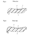
- FIGs. 5 and 6 are sectional views showing conventional examples each of which comprises a pad 1' and a sensor 2' bonded on the pad 1'.
- a slab 3 of about 5 mm in thickness is bonded to cover the sensor 2' as shown in Fig. 5 or a frame laminate 4 of 5 mm in thickness is provided as shown in Fig. 6.
- Such a conventional seat in which the sensor 2' is bonded and the slab 3 or the frame laminate 4 is provided to cover the sensor 2' has disadvantages in that many laminating steps are required and cost is increased due to the laminating.
- a seat with a seat sensor of the present invention comprises a soft pad and a pressure sensitive sheet-like sensor for detecting a human body seated on the pad and is characterized in that the sensor is disposed inside the pad.
- the aforementioned seat with the seat sensor can substantially completely eliminate bad touch due to the presence of the sensor and also eliminate the necessity of providing a slab and a laminate for covering the sensor, thereby allowing easy manufacture and reducing the manufacturing cost.
- the pad is provided with a slit for the sensor formed from a side (any one of front, rear, right, and left sides) toward the center of the pad and the sensor is inserted into the slit.
- the pad is provided with a cavity formed upward from the bottom of the pad, a soft member is inserted into the cavity, and the sensor is disposed between the top surface of the soft member and the ceiling of the cavity.
- the cavity may be formed in such a manner that the lower end thereof is narrower, thereby preventing the soft member from coming off.
- Figs. 1a, 1b and 1c are sectional views showing a seat with a seat sensor according to an embodiment of the present invention
- Fig. 1a is a sectional view taken in the back-and-forth direction
- Fig. 1b is a sectional view taken along the line B-B of Fig. 1a
- Fig. 1c is an exploded structural view.
- a pad 1 is provided with a cavity 5 which is formed in the bottom to extend upward and in which a sensor 2 is attached to the ceiling thereof.
- Filled in the cavity 5 is a slab 6 made of the same soft material as the pad 1 (molded soft polyurethane foam may be used).
- the sensor 2 may be bonded onto the ceiling of the cavity 5 with adhesive agent or adhesive tape. Altematively, the sensor may be bonded on the top of the slab 6.
- a cable 2a connected with the sensor 2 is extended to the rear end of the pad 1 in such a manner that a terminal 2b disposed at an end of the cable projects from the rear end of the pad 1.
- the cavity 5 is formed in a taper configuration in such a manner that the lower portion is narrower so that the slab 6 inserted into the cavity 5 is held in the cavity 5 and is prevented from coming off.
- Figs. 2a and 2b show another embodiments of the present invention.
- the cavity 5 is provided with a protrusion 5a around the opening thereof so that the lower periphery of the slab 6 is engaged with the protrusion 5a, thereby preventing the slab 6 from coming off.
- a used slab 6 is slightly larger than the cavity 5 so that the slab 6 is pressed into the cavity 5 in the elastically compressed state, thereby preventing the slab 6 from coming off.
- the senor 2 has substantially the same size as the area of the ceiling of the cavity 5 in Figs. 1a, 1b, 1c, 2a and 2b, it should be understood that the size of the sensor 2 may be smaller than the ceiling of the cavity 5 as shown in Figs. 7 and 8.
- Fig. 3a is a sectional view of a seat with a seat sensor according to further another embodiment of the present invention and Fig. 3b is an exploded view thereof.
- the pad 1 is provided with a slit 7 extending forward from the rear end, into which the sensor 2 is inserted.
- the slit 7 is provided in a substantially horizontal direction so that the sensor 2 never comes off the slit 7 even without closing the opening of the slit 7.
- a sheet-like slab may be pressed into the slit 7 to prevent the sensor 2 from coming off.
- the pad I may be entirely wrapped with a cover 8 as shown in Fig. 4.
- examples of material of the pad 1 include polyurethane foam and thermoplastics resin fibers (e.g. polypropylene, polyethylene, and polystyrene), just like the conventional example.
- examples of material of the cover 8 shown in Fig. 4 include leather, polyvinyl chloride, moquette, and the like.
- Employed as the sensor 2 may be a pressure sensitive sensor of which the electrical resistance is changed by pressure or a strain gage, just like the conventional example.
- the slit 7 is formed to extend forward from the rear end of the pad 1 in the embodiment shown in Figs. 3a and 3b, the slit 7 may be formed to extend from the front end or side toward the center of the pad 1 in case that the cover 8 wraps the pad 1 as shown in Fig. 4.
- the sensor is disposed inside the pad so that the occupant never feel bad touch even when the occupant sits down on the pad above the sensor.
- This structure can eliminate the necessity of providing a slab or a laminate on the top of the pad, thereby facilitating the manufacture of the seat with seat sensor and thus extremely reducing the manufacturing cost.
Abstract


Description
Claims (10)
- A seat with a seat sensor comprisinga soft pad anda pressure sensitive sheet-like sensor for detecting a human body seated on said pad,said sensor being disposed inside the pad.
- A seat with a seat sensor as claimed in claim 1, wherein said pad is provided with a slit for said sensor formed from a side toward the center of said pad and said sensor is inserted into the slit.
- A seat with a seat sensor as claimed in claim 2, wherein said pad is entirely wrapped with a cover.
- A seat with a seat sensor as claimed in claim 1, wherein said pad is provided with a cavity formed upward from the bottom of said pad, a soft member is inserted into said cavity, and said sensor is disposed between the top surface of said soft member and the ceiling of the cavity.
- A seat with a seat sensor as claimed in claim 4, wherein the lower end of said cavity is narrower than the upper side thereof whereby said soft member is held in said cavity.
- A seat with a seat sensor as claimed in claim 5, wherein said cavity is formed in a taper configuration.
- A seat with a seat sensor as claimed in claim 5, wherein said cavity is provided with a protrusion at the lower end thereof whereby the soft member is held in said cavity.
- A seat with a seat sensor as claimed in claim 4, wherein said sensor is bonded to the ceiling of said cavity.
- A seat with a seat sensor as claimed in claim 8, wherein a cable connected with said sensor is extended to the rear end of said pad.
- A seat with a seat sensor as claimed in claim 9, wherein said cable has a terminal at an end thereof.
Priority Applications (1)
| Application Number | Priority Date | Filing Date | Title |
|---|---|---|---|
| EP02077710A EP1251027B1 (en) | 1997-07-24 | 1998-07-23 | Seat with seat sensor |
Applications Claiming Priority (3)
| Application Number | Priority Date | Filing Date | Title |
|---|---|---|---|
| JP19841397 | 1997-07-24 | ||
| JP198413/97 | 1997-07-24 | ||
| JP9198413A JPH1134710A (en) | 1997-07-24 | 1997-07-24 | Seat with seating sensor |
Related Child Applications (1)
| Application Number | Title | Priority Date | Filing Date |
|---|---|---|---|
| EP02077710A Division EP1251027B1 (en) | 1997-07-24 | 1998-07-23 | Seat with seat sensor |
Publications (3)
| Publication Number | Publication Date |
|---|---|
| EP0893300A2 true EP0893300A2 (en) | 1999-01-27 |
| EP0893300A3 EP0893300A3 (en) | 1999-08-11 |
| EP0893300B1 EP0893300B1 (en) | 2003-03-19 |
Family
ID=16390712
Family Applications (2)
| Application Number | Title | Priority Date | Filing Date |
|---|---|---|---|
| EP02077710A Expired - Lifetime EP1251027B1 (en) | 1997-07-24 | 1998-07-23 | Seat with seat sensor |
| EP98305880A Expired - Lifetime EP0893300B1 (en) | 1997-07-24 | 1998-07-23 | Seat with seat sensor |
Family Applications Before (1)
| Application Number | Title | Priority Date | Filing Date |
|---|---|---|---|
| EP02077710A Expired - Lifetime EP1251027B1 (en) | 1997-07-24 | 1998-07-23 | Seat with seat sensor |
Country Status (4)
| Country | Link |
|---|---|
| US (2) | US6428095B1 (en) |
| EP (2) | EP1251027B1 (en) |
| JP (1) | JPH1134710A (en) |
| DE (2) | DE69812241T2 (en) |
Cited By (9)
| Publication number | Priority date | Publication date | Assignee | Title |
|---|---|---|---|---|
| WO2001064469A2 (en) * | 2000-03-02 | 2001-09-07 | Siemens Automotive Corporation | Method and apparatus for attaching sensors to a seat assembly |
| EP1249362A1 (en) * | 2001-04-12 | 2002-10-16 | Adam Opel Ag | Vehicle seat with a sensor mat to recognize the seat occupant as a person or a child seat |
| LU90917B1 (en) * | 2002-05-02 | 2003-11-03 | Iee Sarl | Device for assembling a vehicle seat |
| FR2845650A1 (en) * | 2002-10-14 | 2004-04-16 | Cera | Motor vehicle seat has weight detection layer embedded in foam padding to avoid discomfort |
| DE10256538A1 (en) * | 2002-12-04 | 2004-06-24 | Adam Opel Ag | Function mat for automobile passenger seat used for heating or detection of seat occupation and attached to seat via double-sided adhesive tape |
| FR2903361A1 (en) * | 2006-07-05 | 2008-01-11 | Cera | Manufacturing seat cushion of automobile vehicle having passenger detection layer, comprises injecting foam precursor mixture in cavity, expanding foam, placing strip in demolding position, and demolding cushion by removing strip |
| CN102421636A (en) * | 2009-04-22 | 2012-04-18 | Iee国际电子工程股份公司 | Foam element production method |
| CN103692911A (en) * | 2012-09-27 | 2014-04-02 | 光阳工业股份有限公司 | Vehicle ride detector |
| CN103723223A (en) * | 2012-10-12 | 2014-04-16 | 光阳工业股份有限公司 | Detecting device and motorcycle with same |
Families Citing this family (42)
| Publication number | Priority date | Publication date | Assignee | Title |
|---|---|---|---|---|
| US7880594B2 (en) * | 2000-09-08 | 2011-02-01 | Automotive Technologies International, Inc. | Switch assemblies and method for controlling vehicular components |
| US6659549B1 (en) * | 2000-10-02 | 2003-12-09 | Autoliv Asp, Inc. | Seat sensor and method for installing the same |
| JPWO2002041736A1 (en) * | 2000-11-21 | 2004-03-25 | 株式会社ブリヂストン | Vehicle seat pad |
| JP4356243B2 (en) * | 2001-01-12 | 2009-11-04 | 株式会社デンソー | Mounting structure for occupant seating sensor |
| US20030038221A1 (en) * | 2001-05-30 | 2003-02-27 | National Seating Company | Truck seat height positioning system |
| GB2383946B (en) | 2001-11-22 | 2005-07-20 | Smartasystems Ltd | A powered adjustable chair having an occupant sensing system. |
| JP4000886B2 (en) * | 2002-04-04 | 2007-10-31 | マツダ株式会社 | Vehicle seat device |
| US6877808B2 (en) * | 2002-04-05 | 2005-04-12 | Siemens Vdo Automotive Corporation | Method and apparatus for attaching a seat sensor mat to a foam cushion |
| GB0304822D0 (en) | 2003-03-03 | 2003-04-09 | Dca Internat Ltd | Improvements in and relating to a pen-type injector |
| FR2854363B1 (en) * | 2003-05-02 | 2005-07-08 | Faurecia Sieges Automobile | METHOD AND DEVICE FOR INTEGRATING A COMPONENT IN A SYNTHETIC FOAM PIECE, SUCH AS A SEAT MATEASSURE, AND A MOTOR VEHICLE SEAT COMPRISING SUCH A COMPONENT |
| CN100496337C (en) * | 2003-06-03 | 2009-06-10 | 株式会社普利司通 | Seat with seating sensor and pad for seat |
| JP2005112335A (en) * | 2003-06-03 | 2005-04-28 | Bridgestone Corp | Seat with seating sensor and pad for seat |
| US7132953B2 (en) * | 2003-06-26 | 2006-11-07 | Lear Corporation | Spring sensor assembly for a vehicle seat cushion |
| JP4205568B2 (en) * | 2003-12-05 | 2009-01-07 | 東洋ゴム工業株式会社 | Manufacturing method of seat pad |
| US7211753B2 (en) * | 2004-11-22 | 2007-05-01 | Sears Manufacturing Co. | Vehicle seat assembly with operator presence switch |
| JP4520882B2 (en) * | 2005-01-27 | 2010-08-11 | 東洋ゴム工業株式会社 | Vehicle seat pad |
| DE102005011742A1 (en) * | 2005-03-11 | 2006-09-14 | Johnson Controls Gmbh | Foam part for a vehicle, in particular for a seat and in particular with sensor means |
| EP1915927B1 (en) * | 2005-08-18 | 2011-03-30 | Bridgestone Corporation | Vehicle seat pad |
| JP4595746B2 (en) * | 2005-08-25 | 2010-12-08 | 株式会社ブリヂストン | Vehicle seat pad |
| JP4839911B2 (en) * | 2006-03-22 | 2011-12-21 | 株式会社ブリヂストン | Foam molded products and molds |
| US7823972B2 (en) * | 2006-11-01 | 2010-11-02 | Gm Global Technology Operations, Inc. | Recliner adjustment utilizing active material sensors |
| JP2008279897A (en) * | 2007-05-10 | 2008-11-20 | Bridgestone Corp | Seat pad for vehicle |
| JP5407127B2 (en) * | 2007-09-03 | 2014-02-05 | トヨタ車体株式会社 | Seat cushion structure for vehicle seat |
| US20090146470A1 (en) * | 2007-09-25 | 2009-06-11 | Tk Holdings Inc. | Vehicle seat |
| JP4770975B2 (en) * | 2009-02-18 | 2011-09-14 | 株式会社デンソー | Seat with occupant detection function and occupant detection device |
| DE202011005145U1 (en) | 2011-02-24 | 2012-06-29 | I.G. Bauerhin Gmbh | Occupancy detection device for detecting the occupancy state of a motor vehicle seat |
| DE102011012367C5 (en) | 2011-02-24 | 2019-04-04 | I.G. Bauerhin Gmbh | Occupancy detection device for detecting the occupancy state of a motor vehicle seat |
| JP5613613B2 (en) * | 2011-04-14 | 2014-10-29 | 日本発條株式会社 | Vehicle seat |
| JP5730795B2 (en) * | 2012-01-19 | 2015-06-10 | トヨタ自動車株式会社 | Vehicle seat and vehicle seat device |
| JP5243639B1 (en) * | 2012-04-06 | 2013-07-24 | 株式会社フジクラ | Seat device |
| JP2014172511A (en) * | 2013-03-08 | 2014-09-22 | Denso Corp | Fitting structure of occupant seating detecting load detector |
| JP5979058B2 (en) | 2013-03-29 | 2016-08-24 | トヨタ紡織株式会社 | Vehicle seat |
| JP6606414B2 (en) * | 2015-11-30 | 2019-11-13 | 株式会社東洋クオリティワン | Vehicle seat pad |
| JP6627697B2 (en) * | 2016-09-12 | 2020-01-08 | 株式会社デンソー | Occupant detection device |
| US11505090B2 (en) | 2017-04-03 | 2022-11-22 | Ts Tech Co., Ltd. | Arrangement structure for biological sensors |
| JP2018175831A (en) * | 2017-04-03 | 2018-11-15 | テイ・エス テック株式会社 | Arrangement structure of biological sensor |
| CN116369889A (en) * | 2017-04-03 | 2023-07-04 | 提爱思科技股份有限公司 | Arrangement structure of biosensor |
| JP6939126B2 (en) * | 2017-06-21 | 2021-09-22 | トヨタ紡織株式会社 | Vehicle seat |
| US20190100122A1 (en) * | 2017-10-04 | 2019-04-04 | Ford Global Technologies, Llc | Waterproof skinned bench seat |
| JP7057497B2 (en) * | 2018-04-27 | 2022-04-20 | テイ・エス テック株式会社 | Biometric information detection system |
| JP2020081171A (en) * | 2018-11-20 | 2020-06-04 | 株式会社ブリヂストン | Seat pad, and manufacturing method for the same |
| WO2023166787A1 (en) * | 2022-03-04 | 2023-09-07 | 住友理工株式会社 | Sensor-equipped seat |
Family Cites Families (18)
| Publication number | Priority date | Publication date | Assignee | Title |
|---|---|---|---|---|
| US3704352A (en) * | 1971-11-17 | 1972-11-28 | John G Fontaine | Composite seat and switch |
| GB1467769A (en) | 1974-04-15 | 1977-03-23 | Nissan Motor | Vehicle having apparatus for inflating vehicle passenger protection bag with seat occupant detector |
| US4865379A (en) * | 1988-02-04 | 1989-09-12 | Tachi-S Co., Ltd. | Automotive seat with heating device |
| EP0345806A3 (en) | 1988-06-10 | 1992-08-05 | Mazda Motor Corporation | Automobile seat assembly |
| US5120980A (en) * | 1990-05-08 | 1992-06-09 | Fontaine Brake Company | Seat cushion switch with delay circuit |
| US5113176A (en) * | 1990-11-13 | 1992-05-12 | Staodyn, Inc. | Lumbar roll with audible alerting capability |
| JP3018700B2 (en) | 1992-01-16 | 2000-03-13 | アイシン精機株式会社 | Dielectric detector |
| JPH05297149A (en) | 1992-04-23 | 1993-11-12 | Aisin Seiki Co Ltd | Dielectric detecting device |
| DE4237072C1 (en) * | 1992-11-03 | 1993-12-02 | Daimler Benz Ag | Resistive film pressure or force sensor for indicating occupation of vehicle seat - has conductive paths for providing series of meandering interdigitated local area transducer electrodes on polymer and semiconductor substrate. |
| DE4406897C1 (en) * | 1994-03-03 | 1995-05-24 | Daimler Benz Ag | Arrangement for detecting occupation of motor vehicle seats |
| DE4417827C2 (en) | 1994-05-20 | 1996-04-04 | Linde Ag | Method and sensor for presence detection of people |
| DE9414164U1 (en) | 1994-09-01 | 1994-11-17 | Zabel Gmbh | Seat contact switch |
| US5474327A (en) * | 1995-01-10 | 1995-12-12 | Delco Electronics Corporation | Vehicle occupant restraint with seat pressure sensor |
| DE19601969A1 (en) | 1996-01-20 | 1997-07-24 | Daimler Benz Ag | Functional mat that can be contacted electrically, in particular sensor mat or heating mat |
| DE19646480A1 (en) * | 1996-11-11 | 1998-05-14 | Karl Schweizer | Automobile seat squab with seat occupation sensor |
| JP3728711B2 (en) * | 1996-11-29 | 2005-12-21 | アイシン精機株式会社 | Seating detection device |
| US5739757A (en) * | 1997-01-30 | 1998-04-14 | Breed Automotive Technology, Inc. | Vehicle passenger weight sensor |
| US5810392A (en) * | 1997-02-15 | 1998-09-22 | Breed Automotive Technology, Inc. | Seat occupant sensing system |
-
1997
- 1997-07-24 JP JP9198413A patent/JPH1134710A/en active Pending
-
1998
- 1998-07-17 US US09/116,906 patent/US6428095B1/en not_active Expired - Lifetime
- 1998-07-23 EP EP02077710A patent/EP1251027B1/en not_active Expired - Lifetime
- 1998-07-23 DE DE69812241T patent/DE69812241T2/en not_active Expired - Lifetime
- 1998-07-23 EP EP98305880A patent/EP0893300B1/en not_active Expired - Lifetime
- 1998-07-23 DE DE69839454T patent/DE69839454D1/en not_active Expired - Lifetime
-
2009
- 2009-04-09 US US12/385,480 patent/US20090261639A1/en not_active Abandoned
Non-Patent Citations (1)
| Title |
|---|
| None |
Cited By (14)
| Publication number | Priority date | Publication date | Assignee | Title |
|---|---|---|---|---|
| WO2001064469A2 (en) * | 2000-03-02 | 2001-09-07 | Siemens Automotive Corporation | Method and apparatus for attaching sensors to a seat assembly |
| WO2001064469A3 (en) * | 2000-03-02 | 2001-12-13 | Siemens Automotive Corp Lp | Method and apparatus for attaching sensors to a seat assembly |
| US7264309B2 (en) | 2000-03-02 | 2007-09-04 | Siemens Vdo Automotive Corporation | Method and apparatus for attaching sensors to a seat assembly |
| EP1249362A1 (en) * | 2001-04-12 | 2002-10-16 | Adam Opel Ag | Vehicle seat with a sensor mat to recognize the seat occupant as a person or a child seat |
| LU90917B1 (en) * | 2002-05-02 | 2003-11-03 | Iee Sarl | Device for assembling a vehicle seat |
| WO2003093050A1 (en) * | 2002-05-02 | 2003-11-13 | Iee International Electronics & Engineering S.A. | Device for assembling a vehicle seat |
| EP1413471A1 (en) * | 2002-10-14 | 2004-04-28 | Centre d'Etude et de Recherche pour l'Automobile ( CERA) | An upholstery element having a foam body, integrating a detection web |
| FR2845650A1 (en) * | 2002-10-14 | 2004-04-16 | Cera | Motor vehicle seat has weight detection layer embedded in foam padding to avoid discomfort |
| DE10256538A1 (en) * | 2002-12-04 | 2004-06-24 | Adam Opel Ag | Function mat for automobile passenger seat used for heating or detection of seat occupation and attached to seat via double-sided adhesive tape |
| FR2903361A1 (en) * | 2006-07-05 | 2008-01-11 | Cera | Manufacturing seat cushion of automobile vehicle having passenger detection layer, comprises injecting foam precursor mixture in cavity, expanding foam, placing strip in demolding position, and demolding cushion by removing strip |
| CN102421636A (en) * | 2009-04-22 | 2012-04-18 | Iee国际电子工程股份公司 | Foam element production method |
| CN103692911A (en) * | 2012-09-27 | 2014-04-02 | 光阳工业股份有限公司 | Vehicle ride detector |
| CN103723223A (en) * | 2012-10-12 | 2014-04-16 | 光阳工业股份有限公司 | Detecting device and motorcycle with same |
| CN103723223B (en) * | 2012-10-12 | 2016-05-18 | 光阳工业股份有限公司 | Checkout gear and there is the motorcycle of checkout gear |
Also Published As
| Publication number | Publication date |
|---|---|
| DE69812241D1 (en) | 2003-04-24 |
| US6428095B1 (en) | 2002-08-06 |
| JPH1134710A (en) | 1999-02-09 |
| US20090261639A1 (en) | 2009-10-22 |
| EP1251027B1 (en) | 2008-05-07 |
| DE69839454D1 (en) | 2008-06-19 |
| EP0893300A3 (en) | 1999-08-11 |
| DE69812241T2 (en) | 2003-12-11 |
| EP1251027A2 (en) | 2002-10-23 |
| EP1251027A3 (en) | 2003-05-21 |
| EP0893300B1 (en) | 2003-03-19 |
Similar Documents
| Publication | Publication Date | Title |
|---|---|---|
| EP0893300A2 (en) | Seat with seat sensor | |
| EP1844978B1 (en) | Interior trim for automobile | |
| US6733072B2 (en) | Padded element for a vehicle, and a method of manufacturing it | |
| JPH09226428A (en) | Functional mat capable of electric contact, particularly sensor mat or heating mat | |
| JP3781957B2 (en) | Vehicle seating sensor arrangement structure | |
| US7942477B1 (en) | Seat provided with electric or electronic equipment | |
| US7530620B2 (en) | Combination harness protector and carpet | |
| US7953522B2 (en) | Vehicle seats | |
| US20090243350A1 (en) | Vehicle seat with a temperature control unit | |
| US4909572A (en) | Automotive seat with reclining device | |
| WO2004107919A1 (en) | Seat with seating sensor and pad for seat | |
| US6986543B2 (en) | Automotive interior trim assembly and pad insertion | |
| US9120397B2 (en) | Attachment structure of weight sensor for seat occupant detection | |
| JP3820084B2 (en) | Seat detection device for seats | |
| JP4029189B2 (en) | Electrical / electronic equipment equipment sheet | |
| US4896919A (en) | Seatback of automotive seat | |
| JP4191620B2 (en) | Cushion pad | |
| US20190077340A1 (en) | Trim elements for vehicle passenger compartment comprising a piezoelectric member | |
| JP3694760B2 (en) | Seat with antenna for occupant detection | |
| JP2004306869A (en) | Seat cushion for vehicle | |
| JP7439649B2 (en) | vehicle headrest | |
| JP4191619B2 (en) | Cushion pad | |
| JP2007055603A5 (en) | ||
| JP2005059646A (en) | Seat with seating sensor | |
| JP2023138078A (en) | Skin integral molding seat pad and vehicular seat |
Legal Events
| Date | Code | Title | Description |
|---|---|---|---|
| PUAI | Public reference made under article 153(3) epc to a published international application that has entered the european phase |
Free format text: ORIGINAL CODE: 0009012 |
|
| AK | Designated contracting states |
Kind code of ref document: A2 Designated state(s): DE FR GB |
|
| AX | Request for extension of the european patent |
Free format text: AL;LT;LV;MK;RO;SI |
|
| PUAL | Search report despatched |
Free format text: ORIGINAL CODE: 0009013 |
|
| AK | Designated contracting states |
Kind code of ref document: A3 Designated state(s): AT BE CH CY DE DK ES FI FR GB GR IE IT LI LU MC NL PT SE |
|
| AX | Request for extension of the european patent |
Free format text: AL;LT;LV;MK;RO;SI |
|
| 17P | Request for examination filed |
Effective date: 19991014 |
|
| AKX | Designation fees paid |
Free format text: DE FR GB |
|
| 17Q | First examination report despatched |
Effective date: 20011115 |
|
| GRAG | Despatch of communication of intention to grant |
Free format text: ORIGINAL CODE: EPIDOS AGRA |
|
| GRAG | Despatch of communication of intention to grant |
Free format text: ORIGINAL CODE: EPIDOS AGRA |
|
| GRAH | Despatch of communication of intention to grant a patent |
Free format text: ORIGINAL CODE: EPIDOS IGRA |
|
| GRAH | Despatch of communication of intention to grant a patent |
Free format text: ORIGINAL CODE: EPIDOS IGRA |
|
| GRAA | (expected) grant |
Free format text: ORIGINAL CODE: 0009210 |
|
| AK | Designated contracting states |
Designated state(s): DE FR GB |
|
| REG | Reference to a national code |
Ref country code: GB Ref legal event code: FG4D |
|
| REF | Corresponds to: |
Ref document number: 69812241 Country of ref document: DE Date of ref document: 20030424 Kind code of ref document: P |
|
| ET | Fr: translation filed | ||
| PLBE | No opposition filed within time limit |
Free format text: ORIGINAL CODE: 0009261 |
|
| STAA | Information on the status of an ep patent application or granted ep patent |
Free format text: STATUS: NO OPPOSITION FILED WITHIN TIME LIMIT |
|
| 26N | No opposition filed |
Effective date: 20031222 |
|
| PGFP | Annual fee paid to national office [announced via postgrant information from national office to epo] |
Ref country code: FR Payment date: 20100805 Year of fee payment: 13 |
|
| PGFP | Annual fee paid to national office [announced via postgrant information from national office to epo] |
Ref country code: GB Payment date: 20100721 Year of fee payment: 13 |
|
| GBPC | Gb: european patent ceased through non-payment of renewal fee |
Effective date: 20110723 |
|
| REG | Reference to a national code |
Ref country code: FR Ref legal event code: ST Effective date: 20120330 |
|
| PG25 | Lapsed in a contracting state [announced via postgrant information from national office to epo] |
Ref country code: FR Free format text: LAPSE BECAUSE OF NON-PAYMENT OF DUE FEES Effective date: 20110801 |
|
| PG25 | Lapsed in a contracting state [announced via postgrant information from national office to epo] |
Ref country code: GB Free format text: LAPSE BECAUSE OF NON-PAYMENT OF DUE FEES Effective date: 20110723 |
|
| REG | Reference to a national code |
Ref country code: DE Ref legal event code: R082 Ref document number: 69812241 Country of ref document: DE Representative=s name: DREISS PATENTANWAELTE PARTG MBB, DE |
|
| REG | Reference to a national code |
Ref country code: DE Ref legal event code: R082 Ref document number: 69812241 Country of ref document: DE Representative=s name: DREISS PATENTANWAELTE PARTG MBB, DE Effective date: 20140828 Ref country code: DE Ref legal event code: R081 Ref document number: 69812241 Country of ref document: DE Owner name: BRIDGESTONE CORPORATION, JP Free format text: FORMER OWNER: BRIDGESTONE CORP., TOKIO/TOKYO, JP Effective date: 20140828 |
|
| PGFP | Annual fee paid to national office [announced via postgrant information from national office to epo] |
Ref country code: DE Payment date: 20140721 Year of fee payment: 17 |
|
| REG | Reference to a national code |
Ref country code: DE Ref legal event code: R119 Ref document number: 69812241 Country of ref document: DE |
|
| PG25 | Lapsed in a contracting state [announced via postgrant information from national office to epo] |
Ref country code: DE Free format text: LAPSE BECAUSE OF NON-PAYMENT OF DUE FEES Effective date: 20160202 |