EP1413007B1 - Antennenspulen für die elektronische artikelsicherung mit variabler wicklungsgeometrie - Google Patents
Antennenspulen für die elektronische artikelsicherung mit variabler wicklungsgeometrie Download PDFInfo
- Publication number
- EP1413007B1 EP1413007B1 EP02794645A EP02794645A EP1413007B1 EP 1413007 B1 EP1413007 B1 EP 1413007B1 EP 02794645 A EP02794645 A EP 02794645A EP 02794645 A EP02794645 A EP 02794645A EP 1413007 B1 EP1413007 B1 EP 1413007B1
- Authority
- EP
- European Patent Office
- Prior art keywords
- coil
- wire
- windings
- antenna
- cross
- Prior art date
- Legal status (The legal status is an assumption and is not a legal conclusion. Google has not performed a legal analysis and makes no representation as to the accuracy of the status listed.)
- Expired - Lifetime
Links
Images

Classifications
-
- H—ELECTRICITY
- H01—ELECTRIC ELEMENTS
- H01Q—ANTENNAS, i.e. RADIO AERIALS
- H01Q7/00—Loop antennas with a substantially uniform current distribution around the loop and having a directional radiation pattern in a plane perpendicular to the plane of the loop
-
- G—PHYSICS
- G08—SIGNALLING
- G08B—SIGNALLING SYSTEMS, e.g. PERSONAL CALLING SYSTEMS; ORDER TELEGRAPHS; ALARM SYSTEMS
- G08B13/00—Burglar, theft or intruder alarms
- G08B13/22—Electrical actuation
- G08B13/24—Electrical actuation by interference with electromagnetic field distribution
- G08B13/2402—Electronic Article Surveillance [EAS], i.e. systems using tags for detecting removal of a tagged item from a secure area, e.g. tags for detecting shoplifting
Definitions
- This invention relates to electronic article surveillance (EAS) antennas, and more particularly to EAS antennas using multiple loop coils having at least one overlapping section.
- EAS electronic article surveillance
- Magnetomechanical EAS antennas can consist of one or more loops of coil wire adapted to transmit and receive preselected EAS frequencies. To optimize the detection performance of magnetomechanical EAS antennas, two coils are utilized, where the phase of each coil in the pair is reversed periodically during transmission, and the coil pairs overlap near the center of the antenna. Such an antenna is disclosed in document EP-A-622 766. Using conventional coil winding techniques, each antenna coil has a uniform cross-section, defined by the number of wire turns per layer multiplied by the number of layers. Given a uniform cross section for each antenna coil, the overlapping coils essentially double the thickness of the antenna at the cross-over point. An antenna with a thick center is undesirable for highly aesthetic, low visual mass antennas. A thin antenna with uniform antenna thickness along the antenna height is preferable.
- An EAS antenna having uniform antenna thickness along the antenna height can be achieved if the individual coil cross-sections are variable with respect to the circumference. If the individual coil thickness is halved at the overlap, the antenna will have uniform thickness along the antenna height. This is accomplished by reducing the number of wire turns per layer along one or more sections of the coil, and simultaneously increasing the number of wire layers on the same sections.
- an electronic article surveillance antenna has a coil loop defined by a plurality of windings of a wire forming a loop.
- the coil loop has a first end and a second end, where a cross-section of the coil loop varies from the first end to the second end.
- the cross-section is defined by the number of windings of wire per a layer of the coil and the number of the layers per end.
- the antenna can further include a second coil loop defined by a second plurality of windings of a second wire forming a second loop.
- the second coil loop has a first end and a second end, where a cross-section of the second coil loop varies from the first end to the second end.
- the cross-section of the second coil loop is defined by the number of windings of the second wire per a layer of the second coil and the number of the layers per end.
- the first ends of the first and the second coil loops are thinner than the second ends of the first and the second coil loops.
- the first and second coil loops are disposed in overlapping orientation with each other near the first ends, resulting in an antenna that is relatively uniform in thickness.
- the first end of the first coil loop can consist of two windings of the first wire and eight layers, and the second end of the first coil loop can consist of four windings of the first wire and four layers.
- the first end of the second coil loop can consist of two windings of the second wire and eight layers, and the second end of the second coil loop can consist of four windings of the second wire and four layers.
- a method of winding a pair of overlapping coil loops to define an electronic article surveillance antenna having a substantially relatively uniform thickness dimension from end to end includes winding a first wire a plurality of windings to define a coil loop having a first end and a second end where the first end is thinner in cross-section that the second end. Then, winding a second wire a plurality of windings to define a second coil loop having a first end and a second end where the first end is thinner in cross-section that the second end. Finally, positioning the first coil loop and the second coil loop where the first ends overlap with each other forming an electronic article surveillance antenna with a substantially relatively uniform thickness.
- EAS antenna coils which emit an electromagnetic field, are commonly constructed of an individual wire that is wound around a coil mandrel.
- the characteristics of the mandrel core, such as size and shape determine the final geometry of the antenna.
- the antenna coil is built by revolving the mandrel about a central axis as the wire is drawn around it. The number of revolutions, or total number of turns, effects the overall size of the antenna coil cross-sectional area.
- the thickness of the antenna coils is determined by the spacing between two side plates in the mandrel. These side plates contain the wire as it is wound around the mandrel core. The winding of the wire typically commences along one side plate where the wire remains adjacent to the said side plate for the full revolution of the mandrel.
- the number of turns per layer can be reduced for a portion of the antenna coil circumference if the spacing between the mandrels varies for each coil section.
- the sections with the greater spacing will accommodate more turns per layer and result in a thicker coil.
- the mandrel side plate spacing decreases for other coil sections, the number of turns per layer and coil thickness will decrease and the number of layers will increase, thus developing a non-uniform coil cross-section per unit length of circumference.
- Any number of turns can be utilized to form coils of varying cross-sectional thickness. A specific example is illustrated hereinbelow.
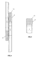
- an EAS antenna 1 is illustrated having two coils 2 each having a first end 4 and a second end 6.
- the coils 2 are positioned end 6 to end 6 where ends 6 of each coil 2 overlap, or cross-over, in antenna region 8.
- the thickness of coil ends 6 are thinner than coil ends 4 resulting in an overall antenna 1 thickness that is substantially relatively uniform from end to end.
- FIGs. 3 and 4 the cross-section of end 4 and end 6, respectively, of coil 2 is illustrated.
- wire 10 is wound four turns per layer, with four layers resulting in a square cross-section.
- wire 10 is wound two turns per layer resulting in 8 layers with a corresponding thinner rectangular cross-section.
- the overall thickness of antenna 1 is nearly uniform from end to end. In conventional coil winding, the coil would have a square profile throughout, resulting in a thicker cross-over region producing an antenna with a thicker center region.
- Winding a coil with a varying cross-section can be used in any EAS coil loop in which a variation in antenna thickness from end to end is desired.
- a plurality of coil loops, or one coil loop, of varying cross-section is contemplated herein.
- one or more coil loops with varying cross-sectional area in combination with one or more coil loops having uniform cross-sectional area is contemplated herein.
Landscapes
- Physics & Mathematics (AREA)
- Engineering & Computer Science (AREA)
- Automation & Control Theory (AREA)
- Computer Security & Cryptography (AREA)
- Electromagnetism (AREA)
- General Physics & Mathematics (AREA)
- Burglar Alarm Systems (AREA)
- Details Of Aerials (AREA)
- Support Of Aerials (AREA)
- Near-Field Transmission Systems (AREA)
Claims (4)
- Antenne für die elektronischeÜberwachung von Artikeln mit
einer ersten Spule, die durch eine erste Anzahl von Windungen eines ersten Drahts definiert ist, wobei die erste Spule ein erstes Ende und ein zweites Ende aufweist, ein Querschnitt der ersten Spule von dem ersten Ende zu dem zweiten Ende variiert, und der Querschnitt durch die Anzahl der Windungen des ersten Drahts pro Schicht der ersten Spule und der Anzahl der Schichten pro Ende definiert ist;
einer zweiten Spule, die durch eine zweite Anzahl von Wicklungen eines zweiten Drahts definiert ist, wobei die zweite Spule ein erstes Ende und ein zweites Ende aufweist, ein Querschnitt der zweiten Spule vom ersten Ende zu dem zweiten Ende variiert, und der Querschnitt der zweiten Spule durch die Anzahl der Windungen des zweiten Drahts pro Schicht der zweiten Spule und der Anzahl der Schichten pro Ende definiert ist, wobei
die ersten Enden der ersten und der zweiten Spule dünner sind als die zweiten Enden der ersten und der zweiten Spule, und
die ersten und die zweiten Spulen derart angeordnet sind, dass sie sich einander in der Nähe der ersten Enden überlappen, wobei die Antenne selbst in ihrer Dicke relativ gleichmäßig ist. - Antenne nach Anspruch 1, wobei
das erste Ende der ersten Spule aus zwei Wicklungen des ersten Drahts und acht Schichten besteht, und das zweite Ende der ersten Spule aus vier Wicklungen des ersten Drahts und vier Schichten besteht, und wobei
das erste Ende der zweiten Spule aus zwei Windungen des zweiten Drahts und acht Schichten besteht und das zweite Ende zweiten Spule aus vier Windungen des zweiten Drahts und vier Schichten besteht. - Verfahren zum Wickeln eines sich überlappenden Spulenpaars, um eine Antenne für eine elektronische Artikelüberwachung zu definieren, die von einem Ende zum anderen Ende eine im Wesentlichen relativ gleichmäßige Dickendimension aufweist mit folgenden Schritten:Wickeln einer Anzahl von Wicklungen mit einem ersten Draht, um eine erste Spule mit einem ersten Ende und einem zweiten Ende zu definieren, wobei das erste Ende in seinem Querschnitt dünner ist als das zweite Ende, der Querschnitt der ersten Spule von dem ersten Ende zu dem zweiten Ende variiert, und der Querschnitt durch die Anzahl der Windungen des ersten Drahts pro Schicht der ersten Spule und der Anzahl der Schichten pro Ende definiert ist;Wickeln einer Anzahl von Windungen mit einem zweiten Draht, um eine zweite Spule mit einem ersten Ende und einem zweiten Ende zu definieren, wobei das erste Ende in seinem Querschnitt dünner ist als das zweite Ende, der Querschnitt der zweiten Spule von dem ersten Ende zu dem zweiten Ende variiert, und der Querschnitt der zweiten Spule durch die Anzahl der Windungen des zweiten Drahts pro Schicht der zweiten Spule und der Anzahl der Schichten pro Ende definiert ist; undAnordnen der ersten und der zweiten Spule derart, dass die ersten Enden einander überlappen, um eine Antenne für die elektronische Artikelüberwachung zu bilden, die eine im Wesentlichen relativ gleichmäßige Dicke aufweist.
- Verfahren nach Anspruch 3 mit weiterhin:Wickeln des ersten Drahts, wobei das erste Ende aus zwei Windungen und acht Schichten des ersten Drahts besteht, und das zweite Ende aus vier Windungen und vier Schichten des ersten Drahts besteht; undWickeln des zweiten Drahts, wobei das erste Ende aus zwei Wicklungen und acht Schichten des zweiten Drahts besteht, und das zweite Ende aus vier Wicklungen und vier Schichten des zweiten Drahts besteht.
Applications Claiming Priority (3)
| Application Number | Priority Date | Filing Date | Title |
|---|---|---|---|
| US09/921,661 US6504513B1 (en) | 2001-08-03 | 2001-08-03 | Electronic article surveillance antenna coils with variable wind geometry |
| US921661 | 2001-08-03 | ||
| PCT/US2002/024168 WO2003015216A2 (en) | 2001-08-03 | 2002-07-31 | Electronic article surveillance antenna coils with variable wind_geometry |
Publications (3)
| Publication Number | Publication Date |
|---|---|
| EP1413007A2 EP1413007A2 (de) | 2004-04-28 |
| EP1413007A4 EP1413007A4 (de) | 2005-11-09 |
| EP1413007B1 true EP1413007B1 (de) | 2006-09-27 |
Family
ID=25445770
Family Applications (1)
| Application Number | Title | Priority Date | Filing Date |
|---|---|---|---|
| EP02794645A Expired - Lifetime EP1413007B1 (de) | 2001-08-03 | 2002-07-31 | Antennenspulen für die elektronische artikelsicherung mit variabler wicklungsgeometrie |
Country Status (7)
| Country | Link |
|---|---|
| US (1) | US6504513B1 (de) |
| EP (1) | EP1413007B1 (de) |
| AT (1) | ATE341109T1 (de) |
| AU (1) | AU2002332435B2 (de) |
| CA (1) | CA2453244A1 (de) |
| DE (1) | DE60215017T2 (de) |
| WO (1) | WO2003015216A2 (de) |
Families Citing this family (2)
| Publication number | Priority date | Publication date | Assignee | Title |
|---|---|---|---|---|
| US7019651B2 (en) * | 2003-06-16 | 2006-03-28 | Sensormatic Electronics Corporation | EAS and RFID systems incorporating field canceling core antennas |
| WO2015028343A1 (en) * | 2013-08-30 | 2015-03-05 | Koninklijke Philips N.V. | Coil arrangement of a mpi system or apparatus |
Family Cites Families (8)
| Publication number | Priority date | Publication date | Assignee | Title |
|---|---|---|---|---|
| US4745401A (en) * | 1985-09-09 | 1988-05-17 | Minnesota Mining And Manufacturing Company | RF reactivatable marker for electronic article surveillance system |
| US4972198A (en) * | 1987-08-31 | 1990-11-20 | Monarch Marking Systems, Inc. | Multiple loop antenna |
| US5103235A (en) * | 1988-12-30 | 1992-04-07 | Checkpoint Systems, Inc. | Antenna structure for an electronic article surveillance system |
| US4999641A (en) * | 1989-09-01 | 1991-03-12 | Monarch Marking Systems, Inc. | Magnetic antenna system having independently controllable electrical field shielding and magnetic field balance |
| US5404147A (en) * | 1992-10-28 | 1995-04-04 | Sensormatic Electronics Corporation | EAS system loop antenna having three loops of different area |
| GB9305085D0 (en) * | 1993-03-12 | 1993-04-28 | Esselte Meto Int Gmbh | Electronic article surveillance system with enhanced geometric arrangement |
| CA2251326C (en) * | 1996-04-10 | 2003-06-17 | Sentry Technology Corporation | Electronic article surveillance system |
| US6118378A (en) * | 1997-11-28 | 2000-09-12 | Sensormatic Electronics Corporation | Pulsed magnetic EAS system incorporating single antenna with independent phasing |
-
2001
- 2001-08-03 US US09/921,661 patent/US6504513B1/en not_active Expired - Lifetime
-
2002
- 2002-07-31 DE DE60215017T patent/DE60215017T2/de not_active Expired - Fee Related
- 2002-07-31 AU AU2002332435A patent/AU2002332435B2/en not_active Ceased
- 2002-07-31 WO PCT/US2002/024168 patent/WO2003015216A2/en not_active Ceased
- 2002-07-31 AT AT02794645T patent/ATE341109T1/de not_active IP Right Cessation
- 2002-07-31 EP EP02794645A patent/EP1413007B1/de not_active Expired - Lifetime
- 2002-07-31 CA CA002453244A patent/CA2453244A1/en not_active Abandoned
Also Published As
| Publication number | Publication date |
|---|---|
| EP1413007A4 (de) | 2005-11-09 |
| ATE341109T1 (de) | 2006-10-15 |
| AU2002332435B2 (en) | 2006-10-26 |
| DE60215017T2 (de) | 2007-04-19 |
| DE60215017D1 (de) | 2006-11-09 |
| WO2003015216A3 (en) | 2003-05-01 |
| AU2002332435C1 (en) | 2003-02-24 |
| WO2003015216A2 (en) | 2003-02-20 |
| US6504513B1 (en) | 2003-01-07 |
| CA2453244A1 (en) | 2003-02-20 |
| EP1413007A2 (de) | 2004-04-28 |
Similar Documents
| Publication | Publication Date | Title |
|---|---|---|
| CA1134422A (en) | Dynamoelectric machine stator having articulated amorphous metal components | |
| US5867100A (en) | Air Coil a security badge and a transponder | |
| KR101282147B1 (ko) | 초전도체들을 이용한 안장형 코일 와인딩, 및 그 제조 방법 | |
| JP2003505877A (ja) | 超伝導磁気コイル | |
| KR19990081772A (ko) | 차량용 교류발전기의 고정자 | |
| US6504513B1 (en) | Electronic article surveillance antenna coils with variable wind geometry | |
| US4401907A (en) | Electric motor coil element and method of manufacturing the same | |
| US4117432A (en) | Deflection yoke with unitary coil frame | |
| AU2002332435A1 (en) | Electronic Article Surveillance Antenna Coils with Variable Wind Geometry | |
| JPS5917705A (ja) | 積層型平板アンテナコイル | |
| JP2000236214A (ja) | 周波数選択鏡面 | |
| JP2003526977A (ja) | 高周波磁束のためのガイド | |
| JP2012070164A (ja) | 低周波用アンテナ | |
| EP0862783B1 (de) | Induktives bauelement | |
| JPH0945279A (ja) | 放電ランプのための電極コイルおよび電極コイルを製造する方法 | |
| JPH0227608Y2 (de) | ||
| US6643116B2 (en) | Radio frequency (RF) security element, coil and capacitor for an RF-security element and method for production thereof | |
| EP0609957A1 (de) | Antwortgerät zur Verwendung in einem Detektierungs- oder Identifizierungssystem und Verfahren zur Herstellung einer Spule für ein solches Antwortgerät | |
| JPH0218613B2 (de) | ||
| JP2004147098A (ja) | バーアンテナ装置 | |
| JP2004166071A (ja) | アンテナ用磁心 | |
| SU1685740A1 (ru) | Способ изготовлени сотовой оболочки | |
| JP2596830Y2 (ja) | 磁 芯 | |
| JP2000223326A (ja) | 変圧器の高直列容量巻線 | |
| JPS6156591B2 (de) |
Legal Events
| Date | Code | Title | Description |
|---|---|---|---|
| PUAI | Public reference made under article 153(3) epc to a published international application that has entered the european phase |
Free format text: ORIGINAL CODE: 0009012 |
|
| 17P | Request for examination filed |
Effective date: 20031229 |
|
| AK | Designated contracting states |
Kind code of ref document: A2 Designated state(s): AT BE BG CH CY CZ DE DK EE ES FI FR GB GR IE IT LI LU MC NL PT SE SK TR |
|
| AX | Request for extension of the european patent |
Extension state: AL LT LV MK RO SI |
|
| RIN1 | Information on inventor provided before grant (corrected) |
Inventor name: RAYMOND, DALE, W. Inventor name: FERNANDEZ, GILBERT Inventor name: TRYER, MARK C. Inventor name: LOPEZ, PEDRO Inventor name: VALADE, FRANKLIN, H., JR. |
|
| A4 | Supplementary search report drawn up and despatched |
Effective date: 20050922 |
|
| GRAP | Despatch of communication of intention to grant a patent |
Free format text: ORIGINAL CODE: EPIDOSNIGR1 |
|
| GRAS | Grant fee paid |
Free format text: ORIGINAL CODE: EPIDOSNIGR3 |
|
| GRAA | (expected) grant |
Free format text: ORIGINAL CODE: 0009210 |
|
| AK | Designated contracting states |
Kind code of ref document: B1 Designated state(s): AT BE BG CH CY CZ DE DK EE ES FI FR GB GR IE IT LI LU MC NL PT SE SK TR |
|
| PG25 | Lapsed in a contracting state [announced via postgrant information from national office to epo] |
Ref country code: AT Free format text: LAPSE BECAUSE OF FAILURE TO SUBMIT A TRANSLATION OF THE DESCRIPTION OR TO PAY THE FEE WITHIN THE PRESCRIBED TIME-LIMIT Effective date: 20060927 Ref country code: IT Free format text: LAPSE BECAUSE OF FAILURE TO SUBMIT A TRANSLATION OF THE DESCRIPTION OR TO PAY THE FEE WITHIN THE PRESCRIBED TIME-LIMIT;WARNING: LAPSES OF ITALIAN PATENTS WITH EFFECTIVE DATE BEFORE 2007 MAY HAVE OCCURRED AT ANY TIME BEFORE 2007. THE CORRECT EFFECTIVE DATE MAY BE DIFFERENT FROM THE ONE RECORDED. Effective date: 20060927 Ref country code: FI Free format text: LAPSE BECAUSE OF FAILURE TO SUBMIT A TRANSLATION OF THE DESCRIPTION OR TO PAY THE FEE WITHIN THE PRESCRIBED TIME-LIMIT Effective date: 20060927 Ref country code: LI Free format text: LAPSE BECAUSE OF FAILURE TO SUBMIT A TRANSLATION OF THE DESCRIPTION OR TO PAY THE FEE WITHIN THE PRESCRIBED TIME-LIMIT Effective date: 20060927 Ref country code: SK Free format text: LAPSE BECAUSE OF FAILURE TO SUBMIT A TRANSLATION OF THE DESCRIPTION OR TO PAY THE FEE WITHIN THE PRESCRIBED TIME-LIMIT Effective date: 20060927 Ref country code: NL Free format text: LAPSE BECAUSE OF FAILURE TO SUBMIT A TRANSLATION OF THE DESCRIPTION OR TO PAY THE FEE WITHIN THE PRESCRIBED TIME-LIMIT Effective date: 20060927 Ref country code: CZ Free format text: LAPSE BECAUSE OF FAILURE TO SUBMIT A TRANSLATION OF THE DESCRIPTION OR TO PAY THE FEE WITHIN THE PRESCRIBED TIME-LIMIT Effective date: 20060927 Ref country code: CH Free format text: LAPSE BECAUSE OF FAILURE TO SUBMIT A TRANSLATION OF THE DESCRIPTION OR TO PAY THE FEE WITHIN THE PRESCRIBED TIME-LIMIT Effective date: 20060927 Ref country code: BE Free format text: LAPSE BECAUSE OF FAILURE TO SUBMIT A TRANSLATION OF THE DESCRIPTION OR TO PAY THE FEE WITHIN THE PRESCRIBED TIME-LIMIT Effective date: 20060927 |
|
| REG | Reference to a national code |
Ref country code: GB Ref legal event code: FG4D |
|
| REG | Reference to a national code |
Ref country code: CH Ref legal event code: EP |
|
| REG | Reference to a national code |
Ref country code: IE Ref legal event code: FG4D |
|
| REF | Corresponds to: |
Ref document number: 60215017 Country of ref document: DE Date of ref document: 20061109 Kind code of ref document: P |
|
| PG25 | Lapsed in a contracting state [announced via postgrant information from national office to epo] |
Ref country code: BG Free format text: LAPSE BECAUSE OF FAILURE TO SUBMIT A TRANSLATION OF THE DESCRIPTION OR TO PAY THE FEE WITHIN THE PRESCRIBED TIME-LIMIT Effective date: 20061227 Ref country code: DK Free format text: LAPSE BECAUSE OF FAILURE TO SUBMIT A TRANSLATION OF THE DESCRIPTION OR TO PAY THE FEE WITHIN THE PRESCRIBED TIME-LIMIT Effective date: 20061227 |
|
| PG25 | Lapsed in a contracting state [announced via postgrant information from national office to epo] |
Ref country code: ES Free format text: LAPSE BECAUSE OF FAILURE TO SUBMIT A TRANSLATION OF THE DESCRIPTION OR TO PAY THE FEE WITHIN THE PRESCRIBED TIME-LIMIT Effective date: 20070107 |
|
| REG | Reference to a national code |
Ref country code: SE Ref legal event code: TRGR |
|
| NLV1 | Nl: lapsed or annulled due to failure to fulfill the requirements of art. 29p and 29m of the patents act | ||
| PG25 | Lapsed in a contracting state [announced via postgrant information from national office to epo] |
Ref country code: PT Free format text: LAPSE BECAUSE OF FAILURE TO SUBMIT A TRANSLATION OF THE DESCRIPTION OR TO PAY THE FEE WITHIN THE PRESCRIBED TIME-LIMIT Effective date: 20070313 |
|
| ET | Fr: translation filed | ||
| REG | Reference to a national code |
Ref country code: CH Ref legal event code: PL |
|
| RIN2 | Information on inventor provided after grant (corrected) |
Inventor name: VALADE, FRANKLIN, H., JR. Inventor name: LOPEZ, PEDRO Inventor name: FERNANDEZ, GILBERT Inventor name: TRYER, MARK C. Inventor name: RAYMOND, DALE, W. |
|
| PLBE | No opposition filed within time limit |
Free format text: ORIGINAL CODE: 0009261 |
|
| STAA | Information on the status of an ep patent application or granted ep patent |
Free format text: STATUS: NO OPPOSITION FILED WITHIN TIME LIMIT |
|
| PGFP | Annual fee paid to national office [announced via postgrant information from national office to epo] |
Ref country code: DE Payment date: 20070831 Year of fee payment: 6 |
|
| 26N | No opposition filed |
Effective date: 20070628 |
|
| PG25 | Lapsed in a contracting state [announced via postgrant information from national office to epo] |
Ref country code: MC Free format text: LAPSE BECAUSE OF NON-PAYMENT OF DUE FEES Effective date: 20070731 Ref country code: GR Free format text: LAPSE BECAUSE OF FAILURE TO SUBMIT A TRANSLATION OF THE DESCRIPTION OR TO PAY THE FEE WITHIN THE PRESCRIBED TIME-LIMIT Effective date: 20061228 |
|
| PG25 | Lapsed in a contracting state [announced via postgrant information from national office to epo] |
Ref country code: EE Free format text: LAPSE BECAUSE OF FAILURE TO SUBMIT A TRANSLATION OF THE DESCRIPTION OR TO PAY THE FEE WITHIN THE PRESCRIBED TIME-LIMIT Effective date: 20060927 |
|
| PG25 | Lapsed in a contracting state [announced via postgrant information from national office to epo] |
Ref country code: IE Free format text: LAPSE BECAUSE OF NON-PAYMENT OF DUE FEES Effective date: 20070731 |
|
| PG25 | Lapsed in a contracting state [announced via postgrant information from national office to epo] |
Ref country code: DE Free format text: LAPSE BECAUSE OF NON-PAYMENT OF DUE FEES Effective date: 20090203 |
|
| PG25 | Lapsed in a contracting state [announced via postgrant information from national office to epo] |
Ref country code: LU Free format text: LAPSE BECAUSE OF NON-PAYMENT OF DUE FEES Effective date: 20070731 Ref country code: CY Free format text: LAPSE BECAUSE OF FAILURE TO SUBMIT A TRANSLATION OF THE DESCRIPTION OR TO PAY THE FEE WITHIN THE PRESCRIBED TIME-LIMIT Effective date: 20060927 |
|
| PG25 | Lapsed in a contracting state [announced via postgrant information from national office to epo] |
Ref country code: TR Free format text: LAPSE BECAUSE OF FAILURE TO SUBMIT A TRANSLATION OF THE DESCRIPTION OR TO PAY THE FEE WITHIN THE PRESCRIBED TIME-LIMIT Effective date: 20060927 |
|
| REG | Reference to a national code |
Ref country code: GB Ref legal event code: 732E Free format text: REGISTERED BETWEEN 20101111 AND 20101117 |
|
| REG | Reference to a national code |
Ref country code: FR Ref legal event code: TP Owner name: SENSORMATIC ELECTRONICS, LLC, US Effective date: 20110913 |
|
| REG | Reference to a national code |
Ref country code: GB Ref legal event code: 732E Free format text: REGISTERED BETWEEN 20150205 AND 20150211 |
|
| REG | Reference to a national code |
Ref country code: GB Ref legal event code: 732E Free format text: REGISTERED BETWEEN 20150305 AND 20150311 |
|
| REG | Reference to a national code |
Ref country code: FR Ref legal event code: PLFP Year of fee payment: 14 |
|
| REG | Reference to a national code |
Ref country code: FR Ref legal event code: TP Owner name: TYCO FIRE & SECURITY GMBH, CH Effective date: 20160115 |
|
| REG | Reference to a national code |
Ref country code: FR Ref legal event code: PLFP Year of fee payment: 15 |
|
| REG | Reference to a national code |
Ref country code: FR Ref legal event code: PLFP Year of fee payment: 16 |
|
| REG | Reference to a national code |
Ref country code: FR Ref legal event code: PLFP Year of fee payment: 17 |
|
| REG | Reference to a national code |
Ref country code: GB Ref legal event code: 732E Free format text: REGISTERED BETWEEN 20191205 AND 20191211 |
|
| PGFP | Annual fee paid to national office [announced via postgrant information from national office to epo] |
Ref country code: GB Payment date: 20200727 Year of fee payment: 19 Ref country code: FR Payment date: 20200727 Year of fee payment: 19 |
|
| PGFP | Annual fee paid to national office [announced via postgrant information from national office to epo] |
Ref country code: SE Payment date: 20200729 Year of fee payment: 19 |
|
| GBPC | Gb: european patent ceased through non-payment of renewal fee |
Effective date: 20210731 |
|
| REG | Reference to a national code |
Ref country code: SE Ref legal event code: EUG |
|
| PG25 | Lapsed in a contracting state [announced via postgrant information from national office to epo] |
Ref country code: GB Free format text: LAPSE BECAUSE OF NON-PAYMENT OF DUE FEES Effective date: 20210731 |
|
| PG25 | Lapsed in a contracting state [announced via postgrant information from national office to epo] |
Ref country code: SE Free format text: LAPSE BECAUSE OF NON-PAYMENT OF DUE FEES Effective date: 20210801 Ref country code: FR Free format text: LAPSE BECAUSE OF NON-PAYMENT OF DUE FEES Effective date: 20210731 |