EP1411399B1 - Holografisches Muster mit feinen Bändern - Google Patents
Holografisches Muster mit feinen Bändern Download PDFInfo
- Publication number
- EP1411399B1 EP1411399B1 EP03022963A EP03022963A EP1411399B1 EP 1411399 B1 EP1411399 B1 EP 1411399B1 EP 03022963 A EP03022963 A EP 03022963A EP 03022963 A EP03022963 A EP 03022963A EP 1411399 B1 EP1411399 B1 EP 1411399B1
- Authority
- EP
- European Patent Office
- Prior art keywords
- linear patterns
- security feature
- linear
- dimensional
- recorded
- Prior art date
- Legal status (The legal status is an assumption and is not a legal conclusion. Google has not performed a legal analysis and makes no representation as to the accuracy of the status listed.)
- Expired - Lifetime
Links
- 238000000034 method Methods 0.000 claims description 30
- 230000008569 process Effects 0.000 claims description 23
- 239000003086 colorant Substances 0.000 claims description 3
- 230000000694 effects Effects 0.000 description 8
- 238000003384 imaging method Methods 0.000 description 5
- 230000002708 enhancing effect Effects 0.000 description 3
- 239000011521 glass Substances 0.000 description 3
- 238000005286 illumination Methods 0.000 description 3
- 238000010276 construction Methods 0.000 description 2
- 230000003287 optical effect Effects 0.000 description 2
- 230000003247 decreasing effect Effects 0.000 description 1
- 230000001747 exhibiting effect Effects 0.000 description 1
- 238000001093 holography Methods 0.000 description 1
- 230000006872 improvement Effects 0.000 description 1
- 230000001678 irradiating effect Effects 0.000 description 1
- 238000012986 modification Methods 0.000 description 1
- 230000004048 modification Effects 0.000 description 1
- 238000011160 research Methods 0.000 description 1
- 210000001525 retina Anatomy 0.000 description 1
- 239000007787 solid Substances 0.000 description 1
- 239000000126 substance Substances 0.000 description 1
- 238000012546 transfer Methods 0.000 description 1
- 238000012795 verification Methods 0.000 description 1
Images



Classifications
-
- G—PHYSICS
- G03—PHOTOGRAPHY; CINEMATOGRAPHY; ANALOGOUS TECHNIQUES USING WAVES OTHER THAN OPTICAL WAVES; ELECTROGRAPHY; HOLOGRAPHY
- G03H—HOLOGRAPHIC PROCESSES OR APPARATUS
- G03H1/00—Holographic processes or apparatus using light, infrared or ultraviolet waves for obtaining holograms or for obtaining an image from them; Details peculiar thereto
- G03H1/04—Processes or apparatus for producing holograms
- G03H1/08—Synthesising holograms, i.e. holograms synthesized from objects or objects from holograms
- G03H1/0808—Methods of numerical synthesis, e.g. coherent ray tracing [CRT], diffraction specific
-
- B—PERFORMING OPERATIONS; TRANSPORTING
- B42—BOOKBINDING; ALBUMS; FILES; SPECIAL PRINTED MATTER
- B42D—BOOKS; BOOK COVERS; LOOSE LEAVES; PRINTED MATTER CHARACTERISED BY IDENTIFICATION OR SECURITY FEATURES; PRINTED MATTER OF SPECIAL FORMAT OR STYLE NOT OTHERWISE PROVIDED FOR; DEVICES FOR USE THEREWITH AND NOT OTHERWISE PROVIDED FOR; MOVABLE-STRIP WRITING OR READING APPARATUS
- B42D25/00—Information-bearing cards or sheet-like structures characterised by identification or security features; Manufacture thereof
- B42D25/20—Information-bearing cards or sheet-like structures characterised by identification or security features; Manufacture thereof characterised by a particular use or purpose
- B42D25/29—Securities; Bank notes
-
- G—PHYSICS
- G03—PHOTOGRAPHY; CINEMATOGRAPHY; ANALOGOUS TECHNIQUES USING WAVES OTHER THAN OPTICAL WAVES; ELECTROGRAPHY; HOLOGRAPHY
- G03H—HOLOGRAPHIC PROCESSES OR APPARATUS
- G03H1/00—Holographic processes or apparatus using light, infrared or ultraviolet waves for obtaining holograms or for obtaining an image from them; Details peculiar thereto
- G03H1/02—Details of features involved during the holographic process; Replication of holograms without interference recording
-
- G—PHYSICS
- G03—PHOTOGRAPHY; CINEMATOGRAPHY; ANALOGOUS TECHNIQUES USING WAVES OTHER THAN OPTICAL WAVES; ELECTROGRAPHY; HOLOGRAPHY
- G03H—HOLOGRAPHIC PROCESSES OR APPARATUS
- G03H1/00—Holographic processes or apparatus using light, infrared or ultraviolet waves for obtaining holograms or for obtaining an image from them; Details peculiar thereto
- G03H1/0005—Adaptation of holography to specific applications
- G03H1/0011—Adaptation of holography to specific applications for security or authentication
-
- G—PHYSICS
- G03—PHOTOGRAPHY; CINEMATOGRAPHY; ANALOGOUS TECHNIQUES USING WAVES OTHER THAN OPTICAL WAVES; ELECTROGRAPHY; HOLOGRAPHY
- G03H—HOLOGRAPHIC PROCESSES OR APPARATUS
- G03H1/00—Holographic processes or apparatus using light, infrared or ultraviolet waves for obtaining holograms or for obtaining an image from them; Details peculiar thereto
- G03H1/02—Details of features involved during the holographic process; Replication of holograms without interference recording
- G03H2001/0204—Object characteristics
-
- G—PHYSICS
- G03—PHOTOGRAPHY; CINEMATOGRAPHY; ANALOGOUS TECHNIQUES USING WAVES OTHER THAN OPTICAL WAVES; ELECTROGRAPHY; HOLOGRAPHY
- G03H—HOLOGRAPHIC PROCESSES OR APPARATUS
- G03H2210/00—Object characteristics
- G03H2210/30—3D object
-
- G—PHYSICS
- G03—PHOTOGRAPHY; CINEMATOGRAPHY; ANALOGOUS TECHNIQUES USING WAVES OTHER THAN OPTICAL WAVES; ELECTROGRAPHY; HOLOGRAPHY
- G03H—HOLOGRAPHIC PROCESSES OR APPARATUS
- G03H2210/00—Object characteristics
- G03H2210/30—3D object
- G03H2210/36—Occluded features resolved due to parallax selectivity
-
- G—PHYSICS
- G03—PHOTOGRAPHY; CINEMATOGRAPHY; ANALOGOUS TECHNIQUES USING WAVES OTHER THAN OPTICAL WAVES; ELECTROGRAPHY; HOLOGRAPHY
- G03H—HOLOGRAPHIC PROCESSES OR APPARATUS
- G03H2210/00—Object characteristics
- G03H2210/40—Synthetic representation, i.e. digital or optical object decomposition
- G03H2210/45—Representation of the decomposed object
- G03H2210/454—Representation of the decomposed object into planes
-
- G—PHYSICS
- G03—PHOTOGRAPHY; CINEMATOGRAPHY; ANALOGOUS TECHNIQUES USING WAVES OTHER THAN OPTICAL WAVES; ELECTROGRAPHY; HOLOGRAPHY
- G03H—HOLOGRAPHIC PROCESSES OR APPARATUS
- G03H2210/00—Object characteristics
- G03H2210/50—Nature of the object
- G03H2210/55—Having particular size, e.g. irresolvable by the eye
Definitions
- the present invention relates to a three-dimensional security feature (holographic fine-line pattern), and in particular, a three-dimensional security feature with enhanced counterfeit deterrent effect using hologram.
- security features fine-line patterns created by printing have been used in the cash vouchers such as securities and banknotes for counterfeit deterrence.
- the conventional security features comprise geometric patterns with complicated combination of fine lines such as wave lines.
- counterfeit of these cash vouchers are increasing.
- security features using diffraction gratings have also been practically used for imparting enhanced counterfeit deterrent effect.
- a security feature using the diffraction grating is often utilized as high level counterfeit deterrence measures as it can express the movement of light, and it can express fine patterns in high resolution, although in two-dimensional images.
- these security feature patterns using the diffraction grating which have been regarded as high level counterfeit deterrence technique are nowadays increasingly counterfeited, because the patterns recorded in it have come to be detected by microscopic observation and observation of the light movement, and because of the spread of the diffraction grating image forming devices using laser two-beam interference.
- CGHs computer generated holograms
- the former process of the two namely replacing the object surface with a set of point light sources, will be described here as a representative process.
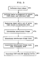
- the shape of the object to be imaged in CGH is defined at step ST1.
- the space arrangements of the object, CGH plane, and reference light are defined.
- the object is divided in the vertical direction with horizontal slices, followed by replacement of the sliced surface with a set of point light sources.
- step ST4 on the basis of these space arrangements, the intensities of the interference fringe between the light arriving from the point light sources constituting the object and the reference light are calculated for each sample point defined on the CGH plane, thereby obtaining the interference fringe data.
- step ST5 the obtained interference fringe data are quantized.
- step ST6 the data are converted into a rectangular data for EB imaging, which are recorded at step ST7 on a medium by means of an EB imaging device, thus finally producing CGH.
- the hidden surface removal process is a process of making a part, which is hidden by other object in front of it, invisible when an object is observed from a certain viewpoint, whereby the information of overlapping of objects is added to retina image, thus exhibiting a three dimensional effect.
- the hidden surface removal process is performed according to the following procedure.
- the region in which the point light source is hidden by objects 1, 2 (the hatched area in FIG. 4 ) is obtained.
- CGH which is produced according to the procedure shown in FIG. 3
- the region in which the point light sources on object 1 are hidden by objects 1, 2 is obtained from the positional relations between points and lines on each slice surface.
- the hidden surface removal process is a process in which, when a sample point of the interference fringe distributing on CGH plane is included in the region in which the point light sources are hidden obtained in the above (solid point in FIG.
- color can be expressed with a CGH, produced by the process in which object surface is replaced by a set of point light sources, by reproducing the CGH with white light.
- verifying information which is a micro-object 11 such as a letter or a figure having such a size as not easily to be recognized by naked eyes, specifically having the largest size not greater than 300 ⁇ m, is arranged behind a covering object 12 having a size larger than micro-object 11 and easily recognizable with naked eyes arranged in front of the micro-object (nearer to the observer relative to the micro-object), at a position where micro-object 11 is covered by the covering object when viewed from the front, so that a viewer E can not observe the verifying information from the front (normal observing direction), and this arrangement is recorded in a CGH 10.
- a micro-object 11 such as a letter or a figure having such a size as not easily to be recognized by naked eyes, specifically having the largest size not greater than 300 ⁇ m
- the hidden surface removal process described above is performed on the set of point light sources expressing the micro-object 11, and the recording is performed in such a manner that'the reconstruction light from the micro-object 11 does not diffract to a region at least between the line 21L and the line 21R in FIG. 5 .
- the line 21L is a line passing the left end of the micro-object 11 and the left end of the covering object 12
- the line 21R is a line passing the right end of the micro-object 11 and the right end of the covering object 12, the front direction being included between the line 21L and the line 21R.
- the line 22L is a line drawn from the left end of the micro-object 11 toward upper left indicating a boundary of a region to which the reconstruction light from the left end of the micro-object 11 does not diffract
- the line 22R is a line drawn from the right end of the micro-object 11 toward upper right indicating a boundary of a region to which the reconstruction light from the right end of the micro-object 11 does not diffract.
- the right side emission angle ⁇ 2 of the object light of micro-object 11 is set larger than the angle ⁇ 2 which is an angle between the line 21R connecting the right end of the micro-object 11 and the right end of the covering object 12 and the front direction
- the left side emission angle ⁇ 3 of the object light of micro-object 11 is set larger than the angle ⁇ 3 which is an angle between the line 21L connecting the left end of the micro-object 11 and the left end of the covering object 12 and the front direction.
- the presence of verifying information is difficult to be noticed because the recorded verifying information is too small to be recognized with naked eyes even under appropriate illumination.
- the presence of the verifying information is difficult to be noticed from the front direction which is the normal observation direction, even with the use of magnifying glass or other enlargement device, thus further enhancing the secrecy of verifying information and decreasing the danger of counterfeit.
- the verification is performed by irradiating the hologram with appropriate illumination and observing it from a predetermined direction other than the front direction using magnifying glass or other enlargement device to reveal the verifying information (micro-object 11).
- the verifying information 11 can be confirmed as it disappears because it becomes behind the covering object 12 when the observation position is moved to the front where the observer's direction is the normal observation direction.
- the present invention is made in order to resolve such problems of the prior art, and it is the object of the present invention to provide a three-dimensional security feature using a hologram which can not be counterfeited by neither of color copying machine nor diffraction grating image forming device. This object is achieved with the features of claim 1.
- the at least two three-dimensional linear patterns are preferably constructed in such a manner that they have at least one interruption in the vicinity of the inner region of the portion where the two linear patterns cross each other.
- the at least two three-dimensional linear patterns can be constructed in such a manner that the outer locating linear pattern has greater width than the inner locating linear pattern at the portion where the two linear patterns cross each other.
- the at least two three-dimensional linear patterns can be constructed in such a manner that micro-letters or geometric micro-figures are three-dimensionally arranged in the inner region of the portion where the two linear patterns cross each other.
- the at least two three-dimensional linear patterns are preferably recorded in such a manner that they are reconstructed within 1 mm depth from the hologram plane.
- the at least two three-dimensional linear patterns can be recorded in such a manner that they are reconstructed in different colors from each other.
- the present invention includes documents on which the three-dimensional security feature described above is provided.
- a hologram is recorded in such a manner that it can be reconstructed to comprise at least two three-dimensional linear patterns when observed locally, wherein one of said at least two linear patterns has at least one portion which crosses the other linear pattern at outer side and at least one portion which crosses the other linear pattern at inner side. Accordingly, the information existing in the inner region of the portion where two linear patterns cross each other is difficult to be noticed, and such information is difficult to be duplicated with color copying machines, or to be counterfeited with diffraction grating image forming devices, thereby significantly enhancing the counterfeiting deterrent effect of the security feature.
- the basic principle of the present invention comprises holographically recording a three-dimensional image with an arrangement in which at least two linear patterns entangle with each other when viewed locally, and especially, recording the image as a computer generated hologram (CGH).
- CGH computer generated hologram
- an original image of a three-dimensional security feature comprising three-dimensionally entangled arrangement is precisely created by means of a 3D-CAD for computer graphics.
- the space arrangements of the three-dimensional securityfeature, CGH plane, and reference light are defined.
- the lines of the three-dimensional security feature are replaced with a set of point light sources or linear light sources, and the hidden surface removal process shown in FIG. 4 is performed.
- interference fringe data is obtained by calculation of intensities of interference fringe between the light coming from each point light source or linear light source constructing the line of the three-dimensional security feature, and a reference light.
- step ST5 the obtained interference fringe data are quantized.
- step ST6 the data are converted into rectangular data for EB imaging.
- step ST7 the data is recorded on a medium by an EB imaging device. In this manner, the three-dimensional security feature of the present invention created utilizing the process in which object surface is replaced with a set of point light sources is produced.
- FIGs. 1(a)-1(c) A specific example of the three-dimensional image with an arrangement in which at least two linear patterns entangle with each other when viewed locally is shown in FIGs. 1(a)-1(c) .
- the image is composed of two spiral linear patterns 1, 2.
- the two spiral linear patterns 1, 2 entangle with each other counterclockwise.
- the direction of spiral entanglement may be either clockwise or counterclockwise, or it may be reversed at somewhere in the midway.
- the substances of the linear patterns 1, 2 are formed as a set of very small points 3 (when the process in which object surface is replaced with a set of point light sources is used).
- a part of linear pattern 1 or 2 which is located behind the other linear pattern 2 or 1 can be interrupted, and in this interrupted region very small micro-letters or geometric micro-figures (micro-patterns) 4 can be three-dimensionally arranged.
- these micro-letters or geometric micro- figures 4 function as verifying information and the other linear pattern 1 or 2 functions as covering object so that the micro-letters or the geometric micro- figures 4 are hidden behind the other linear pattern 1 or 2 and can not be fully observed in an observation from a predetermined direction, for example from the front direction. However, they may be fully observable from the other direction than the predetermined direction, for example from an oblique direction. In this manner, a security feature which is more difficult to be counterfeited is achieved, further improving the security.
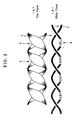
- FIGs. 2(a)-2(c) show another example of three-dimensional image in which at least two linear patterns three-dimensionally entangle with each other when viewed locally, in which FIG. 2(a) is a top view and FIG. 2(b) is a side view.
- the image is composed of, for example, two spiral linear patterns 1 and 2, the two linear patterns 1, 2 entangling with each other counterclockwise in this case.
- the direction of the spiral entanglement may be either clockwise or counterclockwise, or it may be reversed at somewhere in the midway.
- the sense of depth can be enhanced by perspective effect in an arrangement in which the width of the outer linear pattern 1 or 2 is larger than that of inner linear pattern 2 or 1 at the portion where the two linear patterns 1, 2 composing the security feature cross each other with one in the background of the other.
- This portion with larger width is indicated by reference numeral 5.
- the security effect can be enhanced by arranging micro-letters or geometric micro- figures 4 hidden behind the portion with larger width 5 of the outer linear pattern 1 or 2, thus making the counterfeit more difficult.
- the linear patterns 1, 2 and the micro-letters or the geometric micro- figures 4 can be constructed as a set of very small points 3 (see FIG. 1(C) ).
- the linear patterns 1, 2 are effective as counterfeit deterrent security feature when they are recorded with a line width difficult to be recognized by naked eyes. Specifically, it is preferable that the line width is not greater than 300 ⁇ m.
- the plurality of linear patterns 1, 2 which three-dimensionally entangle with each other are preferably recorded in such a manner that they are recognized with naked eyes as a whole as one linear pattern.
- the two linear patterns 1, 2 in FIGs. 1(a)-1(c) may be one linear pattern which is folded back and three-dimensionally entangles with itself.
- linear patterns 1, 2 are preferably arranged within 1 mm depth from the CGH plane, because the farther they are arranged from the CGH plane, the more blurred and more difficult to be observed the reconstructed images become.
- the two linear patterns 1, 2 are recorded in such a manner that they are reconstructed in different colors from each other.
- the process proposed in the patent reference 2 can be employed.
- the hologram constituting the three-dimensional security feature of the present invention can be produced by constructing the linear patterns 1, 2 as a model and photographing the model by an ordinary hologram process using two-beam interference.
- the computer generated hologram process as described above is preferable because the ordinary hologram photographing process is difficult to perform for this width.
- the three-dimensional security feature according to the present invention can be constituted as transfer film or label which can be transferred or attached to documents such as securities and banknotes, such documents being included in the range of the present invention.
- a hologram is recorded in such a manner that it can be reconstructed to comprise at least two three-dimensional linear patterns when locally viewed, wherein at least one of the at least two three-dimensional linear patterns has at least one portion which crosses the other linear pattern at the inner side and at least one portion which crosses the other linear pattern at the outer side.
- the existence of the information is difficult to be noticed from normal observation direction even with the use of enlargement means such as magnifying glass, and the information is impossible to be duplicated with color copying machines or to be counterfeited with diffraction grating image forming devices, thereby significantly enhancing the counterfeit deterrent effect of the security feature.
Landscapes
- Physics & Mathematics (AREA)
- General Physics & Mathematics (AREA)
- Business, Economics & Management (AREA)
- Accounting & Taxation (AREA)
- Finance (AREA)
- Credit Cards Or The Like (AREA)
- Holo Graphy (AREA)
Claims (8)
- Dreidimensionales Sicherheitsmerkmal mit einem Hologramm mit darin aufgezeichneten Interferenzstreifen, wobei das Hologramm derart aufgezeichnet ist, dass es zur Rekonstruktion eines Bildes verwendet wird, das mindestens zwei dreidimensional verschränkte lineare Muster (1, 2) aufweist, wobei mindestens eines der mindestens zwei dreidimensionalen linearen Muster (1, 2) mindestens einen Abschnitt, der das andere lineare Muster an einer einem Betrachter gegenüberliegenden Seite kreuzt, und mindestens einen Abschnitt aufweist, der das andere lineare Muster an einer Seite des Betrachters kreuzt,
wobei das dreidimensionale Sicherheitsmerkmal als ein computererzeugtes Hologramm CGH aufgezeichnet wird, das durch einen Satz von Punktlichtquellen berechnet wird,
wobei das dreidimensionale Sicherheitsmerkmal computergeneriert wird unter Verwendung eines Verfahrens, bei dem eine Objektfläche durch einen Satz von Punktlichtquellen ersetzt wird,
wobei die Linienbreite der linearen Muster kleiner als 300µm ist, und
wobei die mindestens zwei linearen Muster (1, 2) derart aufgezeichnet werden, dass die zwei linearen Muster insgesamt als ein anderes lineares Muster erkannt werden, das bei Betrachtung mit bloßem Auge sich von den mindestens zwei linearen Mustern unterscheidet. - Dreidimensionales Sicherheitsmerkmal nach Anspruch 1, wobei die Interferenzstreifen berechnete Interferenzstreifen zwischen dem Licht, das von dem Satz von Punktlichtquellen, die an einer Oberfläche der zwei dreidimensionalen linearen Muster positioniert sind, und einem Bezugslicht repräsentieren.
- Dreidimensionales Sicherheitsmerkmal nach Anspruch 1 oder 2, wobei mindestens ein Teil der mindestens zwei linearen Muster (1, 2) in der Nähe des Innenbereichs des Abschnitts unterbrochen ist, wo die mindestens zwei linearen Muster einander kreuzen.
- Dreidimensionales Sicherheitsmerkmal nach Anspruch 1, 2 oder 3, wobei die mindestens zwei linearen Muster (1, 2) derart konstruiert sind, dass das außenliegende lineare Muster eine größere Breite als das innenliegende lineare Muster an der Stelle aufweist, wo sich die mindestens zwei linearen Muster miteinander kreuzen.
- Dreidimensionales Sicherheitsmerkmal nach einem der Ansprüche 1 bis 4, wobei die mindestens zwei linearen Muster (1, 2) derart konstruiert sind, dass dreidimensional angeordnete Kleinbuchstaben oder geometrische Kleinfiguren (4) im Innenbereich des Abschnitts angeordnet sind, wo die mindestens zwei linearen Muster einander kreuzen.
- Dreidimensionales Sicherheitsmerkmal nach einem der Ansprüche 1 bis 5, wobei die mindestens zwei linearen Muster (1, 2) derart aufgezeichnet sind, dass sie ausgehend von der CGH-Ebene innerhalb von 1 mm Tiefe rekonstruiert werden.
- Dreidimensionales Sicherheitsmerkmal nach einem der Ansprüche 1 bis 6, wobei die mindestens zwei linearen Muster (1, 2) derart aufgezeichnet werden, dass sie in voneinander unterschiedlichen Farben rekonstruiert werden.
- Dokument, das mit einem dreidimensionalen Sicherheitsmerkmal nach einem der Ansprüche 1 bis 7 versehen ist.
Applications Claiming Priority (2)
| Application Number | Priority Date | Filing Date | Title |
|---|---|---|---|
| JP2002299757A JP4416150B2 (ja) | 2002-10-15 | 2002-10-15 | 立体彩紋 |
| JP2002299757 | 2002-10-15 |
Publications (3)
| Publication Number | Publication Date |
|---|---|
| EP1411399A2 EP1411399A2 (de) | 2004-04-21 |
| EP1411399A3 EP1411399A3 (de) | 2009-09-30 |
| EP1411399B1 true EP1411399B1 (de) | 2012-05-23 |
Family
ID=32040776
Family Applications (1)
| Application Number | Title | Priority Date | Filing Date |
|---|---|---|---|
| EP03022963A Expired - Lifetime EP1411399B1 (de) | 2002-10-15 | 2003-10-09 | Holografisches Muster mit feinen Bändern |
Country Status (3)
| Country | Link |
|---|---|
| US (1) | US7672030B2 (de) |
| EP (1) | EP1411399B1 (de) |
| JP (1) | JP4416150B2 (de) |
Families Citing this family (4)
| Publication number | Priority date | Publication date | Assignee | Title |
|---|---|---|---|---|
| JP4412576B2 (ja) * | 2002-10-16 | 2010-02-10 | 大日本印刷株式会社 | 立体マイクロパターン表示体 |
| JP4670561B2 (ja) * | 2005-09-22 | 2011-04-13 | 凸版印刷株式会社 | 積層シート |
| EP1918913A1 (de) | 2006-10-31 | 2008-05-07 | Thomson Holding Germany GmbH & Co. OHG | Verfahren zur Herstellung einer Sicherheitsmarke auf einem optischen Datenträger |
| US20140355888A1 (en) * | 2013-05-31 | 2014-12-04 | Siemens Product Lifecycle Management Software Inc. | Automatic detection of regular patterns of features |
Citations (1)
| Publication number | Priority date | Publication date | Assignee | Title |
|---|---|---|---|---|
| EP0980767A1 (de) * | 1998-03-06 | 2000-02-23 | Dai Nippon Printing Co., Ltd. | Zwischenträger eines übertragungsaufzeichnungsmaterials, verfahren zur herstellung eines druckes, sowie entsprechendes druckerzeugnis |
Family Cites Families (20)
| Publication number | Priority date | Publication date | Assignee | Title |
|---|---|---|---|---|
| US4969700A (en) | 1987-12-23 | 1990-11-13 | American Bank Note Holographics, Inc. | Computer aided holography and holographic computer graphics |
| US5194971A (en) * | 1986-10-14 | 1993-03-16 | American Bank Note Holographics, Inc. | Computer aided holography and holographic computer graphics |
| US4807971A (en) * | 1986-11-28 | 1989-02-28 | Hideo Nurano | Optical decorative apparatus |
| GB8807029D0 (en) * | 1988-03-24 | 1988-04-27 | Ciba Geigy Ag | Preparing hologram |
| GB9025390D0 (en) * | 1990-11-22 | 1991-01-09 | De La Rue Thomas & Co Ltd | Security device |
| JP3059590B2 (ja) * | 1992-09-30 | 2000-07-04 | 富士通株式会社 | 立体表示方法及び装置 |
| US5638193A (en) * | 1994-12-21 | 1997-06-10 | Tamarack Storage Devices, Inc. | Method and apparatus for azimuthal multiplexing of holograms |
| US5969863A (en) * | 1996-01-26 | 1999-10-19 | Electrowatt Technology Innovation Corp. | Surface pattern including light-diffracting relief structures |
| JPH11316308A (ja) * | 1998-03-06 | 1999-11-16 | Toppan Printing Co Ltd | 回折格子パターン |
| GB9810399D0 (en) * | 1998-05-14 | 1998-07-15 | Rue De Int Ltd | Holographic security device |
| JP3680590B2 (ja) * | 1998-10-26 | 2005-08-10 | 凸版印刷株式会社 | 回折格子パターンとその作製方法 |
| JP3689786B2 (ja) * | 1998-12-22 | 2005-08-31 | 独立行政法人 国立印刷局 | 複写防止模様を有する印刷物 |
| JP3810934B2 (ja) | 1999-01-26 | 2006-08-16 | 大日本印刷株式会社 | 計算機ホログラムおよびその作成方法 |
| DE19915943A1 (de) | 1999-04-09 | 2000-10-12 | Ovd Kinegram Ag Zug | Dekorationsfolie |
| US6311470B1 (en) * | 1999-08-23 | 2001-11-06 | D&W Jewelry, Inc. | Reinforced serpentine rope chain |
| WO2001088113A2 (en) * | 2000-05-03 | 2001-11-22 | Pharmacia & Upjohn Company | Hepatitis c virus helicase crystals, crystallographic structure and methods |
| AU6272101A (en) * | 2000-06-09 | 2001-12-17 | Agency Ind Science Techn | Authenticatable printed matter, and method for producing the same |
| JP2002090548A (ja) * | 2000-09-14 | 2002-03-27 | Toppan Printing Co Ltd | 回折格子から成る表示体 |
| JP2002157327A (ja) * | 2000-11-22 | 2002-05-31 | Kobayashi Kirokushi Co Ltd | ゴミ処理券の共同発行請求システム |
| AT412392B (de) * | 2002-05-14 | 2005-02-25 | Oebs Gmbh | Wertdokument mit einem optischen sicherheitsbereich |
-
2002
- 2002-10-15 JP JP2002299757A patent/JP4416150B2/ja not_active Expired - Fee Related
-
2003
- 2003-01-10 US US10/340,852 patent/US7672030B2/en not_active Expired - Lifetime
- 2003-10-09 EP EP03022963A patent/EP1411399B1/de not_active Expired - Lifetime
Patent Citations (1)
| Publication number | Priority date | Publication date | Assignee | Title |
|---|---|---|---|---|
| EP0980767A1 (de) * | 1998-03-06 | 2000-02-23 | Dai Nippon Printing Co., Ltd. | Zwischenträger eines übertragungsaufzeichnungsmaterials, verfahren zur herstellung eines druckes, sowie entsprechendes druckerzeugnis |
Non-Patent Citations (1)
| Title |
|---|
| SLINGER C ET AL: "Progress and prospects for practical electro-holographic display systems", PROCEEDINGS OF THE INTERNATIONAL SOCIETY FOR OPTICAL ENGINEERING (SPIE), SPIE, USA, vol. 4296, 22 January 2001 (2001-01-22), pages 18 - 32, XP007914807, ISSN: 0277-786X * |
Also Published As
| Publication number | Publication date |
|---|---|
| EP1411399A3 (de) | 2009-09-30 |
| JP2004133330A (ja) | 2004-04-30 |
| EP1411399A2 (de) | 2004-04-21 |
| US20040070800A1 (en) | 2004-04-15 |
| JP4416150B2 (ja) | 2010-02-17 |
| US7672030B2 (en) | 2010-03-02 |
Similar Documents
| Publication | Publication Date | Title |
|---|---|---|
| EP1078302B1 (de) | Holographische sicherheitseinrichtung | |
| EP1296839B1 (de) | Optische vorrichtung | |
| EP1297365B1 (de) | Optische fälschungssicherungsvorrichtung | |
| US20090316238A1 (en) | Optical security device | |
| US20070268536A1 (en) | Optically Variable Security Device | |
| EP1316915A1 (de) | Hologram mit eingespeicherter Authentifizierungsinformation | |
| EP1411398B1 (de) | Dreidimensionales Hologramm mit Mikromustern und ein Dokument dieses enthaltend | |
| US7672030B2 (en) | Holographic fine-line pattern | |
| JPH11316308A (ja) | 回折格子パターン | |
| CA2358688C (en) | An optical material for use in documents of value | |
| JP4946977B2 (ja) | 画像切替型ホログラム | |
| JP5029805B2 (ja) | ホログラム作製方法及びその方法により作製されたホログラム | |
| JP2003295744A (ja) | 計算機ホログラムからなる光情報記録媒体 | |
| JP2005195846A (ja) | 真贋判定情報が記録されたホログラム | |
| JP4390250B2 (ja) | 見る方向によって形状が異なる立体像が記録されたホログラム | |
| JP4849252B2 (ja) | セキュリティ用ホログラムの作製方法 | |
| JP4784782B2 (ja) | 真贋判定情報が記録されたホログラム | |
| Stępień | Computer generated holograms versus synthetic diffraction gratings in optically variable devices |
Legal Events
| Date | Code | Title | Description |
|---|---|---|---|
| PUAI | Public reference made under article 153(3) epc to a published international application that has entered the european phase |
Free format text: ORIGINAL CODE: 0009012 |
|
| AK | Designated contracting states |
Kind code of ref document: A2 Designated state(s): AT BE BG CH CY CZ DE DK EE ES FI FR GB GR HU IE IT LI LU MC NL PT RO SE SI SK TR |
|
| AX | Request for extension of the european patent |
Extension state: AL LT LV MK |
|
| PUAL | Search report despatched |
Free format text: ORIGINAL CODE: 0009013 |
|
| AK | Designated contracting states |
Kind code of ref document: A3 Designated state(s): AT BE BG CH CY CZ DE DK EE ES FI FR GB GR HU IE IT LI LU MC NL PT RO SE SI SK TR |
|
| AX | Request for extension of the european patent |
Extension state: AL LT LV MK |
|
| 17P | Request for examination filed |
Effective date: 20100211 |
|
| 17Q | First examination report despatched |
Effective date: 20100409 |
|
| AKX | Designation fees paid |
Designated state(s): DE FR GB |
|
| GRAP | Despatch of communication of intention to grant a patent |
Free format text: ORIGINAL CODE: EPIDOSNIGR1 |
|
| GRAS | Grant fee paid |
Free format text: ORIGINAL CODE: EPIDOSNIGR3 |
|
| GRAA | (expected) grant |
Free format text: ORIGINAL CODE: 0009210 |
|
| AK | Designated contracting states |
Kind code of ref document: B1 Designated state(s): DE FR GB |
|
| REG | Reference to a national code |
Ref country code: GB Ref legal event code: FG4D |
|
| REG | Reference to a national code |
Ref country code: DE Ref legal event code: R096 Ref document number: 60340985 Country of ref document: DE Effective date: 20120719 |
|
| PLBE | No opposition filed within time limit |
Free format text: ORIGINAL CODE: 0009261 |
|
| STAA | Information on the status of an ep patent application or granted ep patent |
Free format text: STATUS: NO OPPOSITION FILED WITHIN TIME LIMIT |
|
| 26N | No opposition filed |
Effective date: 20130226 |
|
| REG | Reference to a national code |
Ref country code: DE Ref legal event code: R097 Ref document number: 60340985 Country of ref document: DE Effective date: 20130226 |
|
| REG | Reference to a national code |
Ref country code: FR Ref legal event code: PLFP Year of fee payment: 13 |
|
| REG | Reference to a national code |
Ref country code: FR Ref legal event code: PLFP Year of fee payment: 14 |
|
| REG | Reference to a national code |
Ref country code: FR Ref legal event code: PLFP Year of fee payment: 15 |
|
| REG | Reference to a national code |
Ref country code: FR Ref legal event code: PLFP Year of fee payment: 16 |
|
| PGFP | Annual fee paid to national office [announced via postgrant information from national office to epo] |
Ref country code: GB Payment date: 20211022 Year of fee payment: 19 |
|
| PGFP | Annual fee paid to national office [announced via postgrant information from national office to epo] |
Ref country code: FR Payment date: 20211021 Year of fee payment: 19 |
|
| PGFP | Annual fee paid to national office [announced via postgrant information from national office to epo] |
Ref country code: DE Payment date: 20220620 Year of fee payment: 20 |
|
| GBPC | Gb: european patent ceased through non-payment of renewal fee |
Effective date: 20221009 |
|
| P01 | Opt-out of the competence of the unified patent court (upc) registered |
Effective date: 20230524 |
|
| PG25 | Lapsed in a contracting state [announced via postgrant information from national office to epo] |
Ref country code: FR Free format text: LAPSE BECAUSE OF NON-PAYMENT OF DUE FEES Effective date: 20221031 |
|
| REG | Reference to a national code |
Ref country code: DE Ref legal event code: R071 Ref document number: 60340985 Country of ref document: DE |
|
| PG25 | Lapsed in a contracting state [announced via postgrant information from national office to epo] |
Ref country code: GB Free format text: LAPSE BECAUSE OF NON-PAYMENT OF DUE FEES Effective date: 20221009 |