EP1411301A2 - Dunstabzugseinrichtung - Google Patents
Dunstabzugseinrichtung Download PDFInfo
- Publication number
- EP1411301A2 EP1411301A2 EP03021391A EP03021391A EP1411301A2 EP 1411301 A2 EP1411301 A2 EP 1411301A2 EP 03021391 A EP03021391 A EP 03021391A EP 03021391 A EP03021391 A EP 03021391A EP 1411301 A2 EP1411301 A2 EP 1411301A2
- Authority
- EP
- European Patent Office
- Prior art keywords
- water
- extractor hood
- extractor
- line
- movable line
- Prior art date
- Legal status (The legal status is an assumption and is not a legal conclusion. Google has not performed a legal analysis and makes no representation as to the accuracy of the status listed.)
- Withdrawn
Links
Images

Classifications
-
- F—MECHANICAL ENGINEERING; LIGHTING; HEATING; WEAPONS; BLASTING
- F24—HEATING; RANGES; VENTILATING
- F24C—DOMESTIC STOVES OR RANGES ; DETAILS OF DOMESTIC STOVES OR RANGES, OF GENERAL APPLICATION
- F24C15/00—Details
- F24C15/20—Removing cooking fumes
Definitions
- the present invention relates to an extractor device for attachment via a Cooking.
- the object of the present invention is to provide an extractor hood device to provide additional functions in addition to the function of extracting cooking fumes has, so that the extractor device is more versatile.
- the water delivery device has a metering device, such as a metering valve or a tap, so that the required amount of water can be dispensed in doses.
- the water dispenser has such a flexible line that this over the entire area of the hob can be manipulated so that at any location below the extractor hood or water can be supplied to the hob.
- the movable pipe can do this as a flexible pipe or a flexible one Hose line may be formed, the movable line on the fume extractor accomplished via a two-axis, cardanic rotating union for water so that the entire area of the hotplate is overlaid by a Swiveling movement of the movable pipe can be supplied with water.
- the extractor hood is at the attachment point a flexible hose line on the movable line on the extractor hood provided to manipulate the hose line over the entire area of the Ensure the hotplate.
- the flexible hose line has a guide device attached to the extractor device for guiding and holding the flexible hose line, the guide device preferably as An eyelet is formed through which the hose line can be slidably guided.
- the movable Pipe have a telescopic extension to the water supply throughout Ensure the area of the hotplate.
- the movable line have an operating position in which the movable line can be manipulated over the hotplate and have a parking position in which the line from the hob area, especially from the vapor stream. This makes it possible for the movable Line in its parking position does not interfere when not in use above the hotplate and is outside of the haze stream, so that the moving Line can be avoided.
- the metering device is arranged at the downstream end portion of the movable pipe. That has the advantage, that there is no water in the moving pipe after switching off the dosing device can drip. Furthermore, the movable line can be downstream the metering device. This has the advantage that at the end of the moving Line no heavy metering device is arranged.
- the water delivery device with an actuating device for opening and closing the metering device Mistake.
- the actuator can be designed as a mechanically actuated lever or button that the metering device operated directly via a mechanical connection.
- the actuator can also be designed as an electrical switching device that the metering device opens and closes via an electrical control line.
- the water delivery device has a water quantity preselector over which a preselected quantity of Water can be dispensed, the water quantity preselection device preferably being a flow measuring device has whose signal controls the opening time of the metering device.
- the input device for preselecting the amount of water on the extractor device is preferred, in particular on a front wall or side wall of the extractor hood device, arranged.
- the metering device is as an electromagnetically controllable valve is formed, which is preferred either over the mechanical actuator or can be controlled via the input device.
- the water dispenser has a water vessel, which is preferably below the water outlet of the water delivery device is removably positionable.
- the addition of Put water in a pot using a water container This allows the movable line be trained very short and does not interfere with freedom of movement below the Extractor device.
- the water delivery device supplied via a permanently installed domestic water pipe, which has the advantage that any amount of water is available.
- the Water dispenser can be provided with a refillable water storage tank. This makes you independent of a domestic water supply connection and still has the advantages of a water dispensing device arranged on the extractor hood.
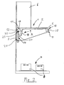
- an extractor hood device 1 has a housing 2 with a rear wall 3, a side wall 4, a front wall 5 and an air exhaust chimney 6.
- the extractor hood also has an air conveyor (not shown), with which with haze, Oil and fat-laden air, which arises above a hotplate 7, via a filter device (not shown), which preferably a grease filter, an odor filter and possibly has a moisture separator, is suctioned off.
- the extractor device can be used as So-called air circulation hood, in which the extracted and filtered air is returned to the room will, and be designed as an exhaust hood, in which the air laden with haze is transported outside the room.
- the extractor device 1 is provided with a water dispensing device 9 which preferably attached to the side wall 4 or the rear wall 3 within the housing 2 is.
- the water dispenser 9 has a metering device 10 for metered dispensing of water, which is designed according to FIG. 1 as an electromagnetically controllable throttle valve 11.
- the metering device 10 is connected to a domestic water line 12 (only shown symbolically) connected.
- a flow measuring device is located downstream of the metering device 10 13 arranged. Downstream of the flow measuring device 13 is a movable one Line 14 arranged that can be manipulated or manipulated over the entire area of the hotplate is movable.
- the movable line 14 has a connection to the flow measuring device 13 a flexible hose section 15 and followed by a pipe 16.
- the pipe 16 is adjacent to the connection area at the upper end section the flexible hose 15 via a swivel 19 on the side wall 4 of the housing 2 attached.
- the water dispensing device 9 has an actuating device for opening and closing the metering device 10.
- the actuating device 20 can on the movable Line 14, on the metering device 10 or on the front wall 5 adjacent to the input device 18 or integrated into the input device 18 (as shown in particular in the present exemplary embodiment according to FIG. 1).
- the movable line 14 is positioned over the desired food container 8 and opened the metering valve via the actuating device 20 until the desired one Amount of water has flowed into the food container, after which the actuator 20 returns to the closed position by releasing it.
- Another Functionality is a certain amount of water via the water quantity preselection device 17 preselected, the movable line 14 positioned over the food container 8 and then actuates the actuator 20 to start, after which the metering device 10 is opened and water is discharged for as long via the flow measuring device 13 until the preselected amount of water is dispensed. Then the dosing device 10 closed again.
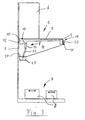
- a second exemplary embodiment is arranged above a hotplate 7 Extractor hood 1 shown with a water dispenser 9, only differing from the exemplary embodiment shown in FIG. 1 Features are explained in more detail.
- the water dispenser 9 has one flexible hose 21 which is attached to the housing 2 of the extractor device 1 Guide device 22 is guided extendable.
- the guide device 22 has for this purpose an eyelet 23 through which the flexible hose 21 can be slidably guided.
- a third exemplary embodiment is arranged above a hotplate 7 Extractor hood 1 shown with a water dispenser 9, wherein only those that differ from the exemplary embodiment according to FIG. 1 Characteristics are shown.
- Cup holder 24 can be a cup 25 recordable. With this arrangement, the water can enter the cup 25 are metered and fed to the food containers 8 with the cup 25.
- the movable line can on the extractor hood via a two-axis, cardanic rotating union (not shown) for water at the outlet of the metering device 10 or the flow measuring device 13 may be arranged.
- the movable line 14 with a telescopic extension may be provided to any water dispensing position easy to reach above the hob.
- the movable line 14 can have two positions take in.
- the movable line 14 has an operating position 26 in which the movable Line 14 can be moved or manipulated over the hotplate 7 and has it a parking position 27, in which the movable line out of the hob area is moved and thus removed from the haze stream.
- the movable line 14 is downstream arranged the metering device 10.
- the metering device 10 it is also possible to use the metering device 10 to be arranged at the downstream end section of the movable line 14.
- the metering device 10 designed as an electromagnetic control flap 11 can also the flow rate can be set using a rotary or slide button so that the volume flow can be adjusted like with a tap.
- the metering device 10 a simple faucet such as a ball valve with one on it movable line 14 may be formed. This can indicate the presence of a Flow measuring device can be dispensed with.
Landscapes
- Engineering & Computer Science (AREA)
- Chemical & Material Sciences (AREA)
- Combustion & Propulsion (AREA)
- Mechanical Engineering (AREA)
- General Engineering & Computer Science (AREA)
- Apparatus For Making Beverages (AREA)
- Extraction Or Liquid Replacement (AREA)
Abstract
Description
Claims (20)
- Dunstabzugseinrichtung zum Anbringen über einer Kochstelle (7),
dadurch gekennzeichnet, dass die Dunstabzugseinrichtung mit einer Wasserabgabeeinrichtung (9) versehen ist. - Dunstabzugseinrichtung nach Anspruch 1,
dadurch gekennzeichnet, dass die Wasserabgabeeinrichtung (9) eine Dosiereinrichtung (10) zum dosierten Abgeben von Wasser, bevorzugt ein Dosierventil oder einen Wasserhahn, hat. - Dunstabzugseinrichtung nach Anspruch 1 oder 2,
dadurch gekennzeichnet, dass die Wasserabgabeeinrichtung (9) eine bewegliche Leitung (14) hat, die über den gesamten Bereich der Kochstelle (7) manipulierbar ist. - Dunstabzugseinrichtung nach Anspruch 3,
dadurch gekennzeichnet, dass die bewegliche Leitung (14) als eine flexible Rohrleitung, die bevorzugt eine Vielzahl von Kugelgelenken hat, oder als eine flexible Schlauchleitung (15, 21) ausgebildet ist. - Dunstabzugseinrichtung nach Anspruch 3 oder 4,
dadurch gekennzeichnet, dass die bewegliche Leitung (14) eine zweiachsige, kardanische Drehdurchführung für Wasser hat, die bevorzugt am Befestigungspunkt der beweglichen Leitung (14) an der Dunstabzugseinrichtung angeordnet ist. - Dunstabzugseinrichtung nach einem der Ansprüche 3 bis 5,
dadurch gekennzeichnet, dass die bewegliche Leitung (14) benachbart zum Befestigungspunkt an der Dosiereinrichtung 10 einen flexiblen Schlauchabschnitt (15) und daran anschließend eine Rohrleitung (16) hat, und/oder dass die Rohrleitung (16) über ein Drehgelenk (19) an der Dunstabzugseinrichtung schwenkbar gelagert ist. - Dunstabzugseinrichtung nach einem der Ansprüche 3 bis 6,
dadurch gekennzeichnet, dass an der Dunstabzugseinrichtung eine Führungseinrichtung (22) zum Führen und Halten der flexiblen Schlauchleitung (21) vorgesehen ist, wobei die Führungseinrichtung bevorzugt als Öse (23) ausgebildet ist, durch die die Schlauchleitung (21) gleitend beweglich führbar ist. - Dunstabzugseinrichtung nach einem der vorstehenden Ansprüche 3 bis 7, dadurch gekennzeichnet, dass die bewegliche Leitung (14) einen teleskopischen Auszug hat.
- Dunstabzugseinrichtung nach einem der Ansprüche 3 bis 8,
dadurch gekennzeichnet, dass die bewegliche Leitung (14) eine Betriebsposition (26) hat, bei der die bewegliche Leitung (14) über der Kochstelle (7) manipulierbar ist und eine Parkposition (27) hat, bei der die bewegliche Leitung (14) aus dem Kochstellenbereich (7), insbesondere aus dem Dunststrom, entfernt ist. - Dunstabzugseinrichtung nach einem der Ansprüche 2 bis 9,
dadurch gekennzeichnet, dass die Dosiereinrichtung (10) am stromabseitigen Endabschnitt der beweglichen Leitung (14) angeordnet ist, oder dass die bewegliche Leitung (14) stromab der Dosiereinrichtung (10) angeordnet ist. - Dunstabzugseinrichtung nach einem der Ansprüche 1 bis 10,
dadurch gekennzeichnet, dass die Wasserabgabeeinrichtung (9) mit einer Betätigungseinrichtung (20) zum Öffnen und Schließen der Dosiereinrichtung (10) versehen ist. - Dunstabzugseinrichtung nach Anspruch 9,
dadurch gekennzeichnet, dass die Betätigungseinrichtung (20) an der Dunstabzugseinrichtung und/oder an der beweglichen Leitung (14) angeordnet ist. - Dunstabzugseinrichtung nach einem der Ansprüche 1 bis 12,
dadurch gekennzeichnet, dass die Wasserabgabeeinrichtung (9) eine Wassermengenvorwahleinrichtung (17) hat, über die eine vorgewählte Menge an Wasser abgebbar ist. - Dunstabzugseinrichtung nach Anspruch 13,
dadurch gekennzeichnet, dass die Wassermengenvorwahleinrichtung (17) eine Durchflussmesseinrichtung (13) hat, deren Signal die Öffnungsdauer der Dosiereinrichtung (10) steuert. - Dunstabzugseinrichtung nach einem der Ansprüche 12 oder 13,
dadurch gekennzeichnet, dass die Wasserabgabeeinrichtung (9) eine Eingabeeinrichtung (18) zum Vorwählen der Wassermenge hat, die bevorzugt an der Dunstabzugseinrichtung, insbesondere an einer Vorderwand (5) der Dunstabzugseinrichtung angeordnet ist. - Dunstabzugseinrichtung nach einem der Ansprüche 2 bis 15,
dadurch gekennzeichnet, dass die Dosiereinrichtung (10) ein elektromagnetisch steuerbares Ventil (11), bevorzugt ein elektromagnetisch einstellbares Drosselventil, hat. - Dunstabzugseinrichtung nach Anspruch 11 und/oder 15,
dadurch gekennzeichnet, dass die Dosiereinrichtung (10) über die Betätigungseinrichtung (20) und/oder über die Eingabeeinrichtung (18) steuerbar ist. - Dunstabzugseinrichtung nach einem der Ansprüche 1 bis 17,
dadurch gekennzeichnet, dass die Wasserabgabeeinrichtung (9) ein Wassergefäß (15) hat, das bevorzugt unterhalb des Wasserauslaufs der Wasserabgabeeinrichtung (9) entnehmbar positionierbar ist. - Dunstabzugseinrichtung nach einem der Ansprüche 1 bis 18,
dadurch gekennzeichnet, dass die Wasserabgabeeinrichtung (9) über eine Hauswasserleitung (12) speisbar ist. - Dunstabzugseinrichtung nach einem der Ansprüche 1 bis 19,
dadurch gekennzeichnet, dass die Wasserabgabeeinrichtung (9) einen auffüllbaren Wasservorratstank hat.
Applications Claiming Priority (2)
| Application Number | Priority Date | Filing Date | Title |
|---|---|---|---|
| DE2002144984 DE10244984A1 (de) | 2002-09-26 | 2002-09-26 | Dunstabzugseinrichtung |
| DE10244984 | 2002-09-26 |
Publications (2)
| Publication Number | Publication Date |
|---|---|
| EP1411301A2 true EP1411301A2 (de) | 2004-04-21 |
| EP1411301A3 EP1411301A3 (de) | 2005-08-31 |
Family
ID=31969624
Family Applications (1)
| Application Number | Title | Priority Date | Filing Date |
|---|---|---|---|
| EP03021391A Withdrawn EP1411301A3 (de) | 2002-09-26 | 2003-09-22 | Dunstabzugseinrichtung |
Country Status (2)
| Country | Link |
|---|---|
| EP (1) | EP1411301A3 (de) |
| DE (1) | DE10244984A1 (de) |
Cited By (1)
| Publication number | Priority date | Publication date | Assignee | Title |
|---|---|---|---|---|
| CN103216668A (zh) * | 2013-01-19 | 2013-07-24 | 上海创绿酒店设备有限公司 | 一种用于铁板烧设备的风阀调节装置 |
Families Citing this family (2)
| Publication number | Priority date | Publication date | Assignee | Title |
|---|---|---|---|---|
| CN103123135B (zh) * | 2013-01-17 | 2015-12-02 | 宁波方太厨具有限公司 | 整流板与碰爪的连接结构及应用有该连接结构的油烟机 |
| US12402742B2 (en) | 2021-09-20 | 2025-09-02 | Midea Group Co., Ltd. | Microwave with water dispenser |
Family Cites Families (8)
| Publication number | Priority date | Publication date | Assignee | Title |
|---|---|---|---|---|
| US3672126A (en) * | 1970-07-20 | 1972-06-27 | Goettle Bros Metal Products In | Air conditioner |
| JPS60111834A (ja) * | 1983-11-18 | 1985-06-18 | Matsushita Electric Ind Co Ltd | 排煙装置 |
| US4822385A (en) * | 1987-07-14 | 1989-04-18 | Maysteel Corporation | Exhaust cleansing apparatus |
| AT401102B (de) * | 1994-09-08 | 1996-06-25 | Lechner Josef Ing | Dunstabzugshaube od. dgl. |
| DE19509611C2 (de) * | 1995-03-16 | 1998-08-06 | Rentschler Reven Lueftungssyst | Dunstabzugshaube |
| DE19813480C2 (de) * | 1998-03-26 | 2001-07-05 | Alexander Klingholz | Modulares Küchensystem für mobile Küchenelemente |
| CH692516A5 (fr) * | 1998-07-29 | 2002-07-15 | Giovanna Sa H | Hotte de cuisine autonettoyante. |
| US6079407A (en) * | 1999-10-08 | 2000-06-27 | Lai; Hung-Chih | Ventilator hood for a stove |
-
2002
- 2002-09-26 DE DE2002144984 patent/DE10244984A1/de not_active Withdrawn
-
2003
- 2003-09-22 EP EP03021391A patent/EP1411301A3/de not_active Withdrawn
Cited By (2)
| Publication number | Priority date | Publication date | Assignee | Title |
|---|---|---|---|---|
| CN103216668A (zh) * | 2013-01-19 | 2013-07-24 | 上海创绿酒店设备有限公司 | 一种用于铁板烧设备的风阀调节装置 |
| CN103216668B (zh) * | 2013-01-19 | 2017-12-22 | 上海创绿餐饮设备有限公司 | 一种用于铁板烧设备的风阀调节装置 |
Also Published As
| Publication number | Publication date |
|---|---|
| DE10244984A1 (de) | 2004-04-01 |
| EP1411301A3 (de) | 2005-08-31 |
Similar Documents
| Publication | Publication Date | Title |
|---|---|---|
| DE3611715A1 (de) | Kaffeemaschine | |
| EP4281708B1 (de) | Gargerät für die grossküche mit fettabsaugeinrichtung, sowie verfahren zum betreiben eines solchen gargeräts mit fettabsaugung | |
| EP2272408A1 (de) | Getränkebereitungsmaschine und Verfahren zum Reinigen einer Getränkebereitungsmaschine | |
| DE19723312A1 (de) | Wassserauslaufventilanordnung | |
| EP2080458B1 (de) | Dampfrohr für einen Kaffeevollautomaten | |
| AT398272B (de) | Kaffeemaschine | |
| DE4031764A1 (de) | Einloch-mischbatterie fuer spueltische | |
| DE3717678A1 (de) | Haushaltgeraet zum bereiten von tee | |
| DE102011109282B4 (de) | Gargerät mit Fettablauf | |
| EP3405077A1 (de) | Teeautomat, system und verfahren zur steuerung eines teeautomaten | |
| EP3180984B1 (de) | Gargerät | |
| DE60218462T2 (de) | Automatisches teigwarengargerät für restaurants, spaghettihäuser und dergleichen | |
| EP1862099B1 (de) | Küchengerät mit Dampferzeuger und absenkbarer Heizvorrichtung | |
| EP0809455B1 (de) | Kaltwasservorratsbehälter für eine elektrische haushaltsbrühgetränkemaschine | |
| DE10244984A1 (de) | Dunstabzugseinrichtung | |
| EP2605661B1 (de) | Dampfgargerätvorrichtung | |
| DE3836877C1 (en) | Device in a water heater for preventing dripping | |
| DE60300308T2 (de) | Küchenmöbel zum Kochen von Nahrungsmitteln | |
| DE2944264A1 (de) | Haushaltgeraet zum bereiten heisser getraenke wie kaffee, tee o.dgl. | |
| DE202012008555U1 (de) | Reinigungsvorrichtung zur Reinigung von Spritzpistolen | |
| DE69818518T2 (de) | Abgabevorrichtung und behältereinheit mit einer solchen vorrichtung | |
| DE102012222029A1 (de) | Flüssigkeitsbehälter | |
| DE2648330A1 (de) | Vorrichtung zur entnahme einer probe aus einer verpumpten begrenzten menge einer inhomogenen fluessigkeit | |
| DE19907150A1 (de) | Bottichgerät zum Garen von Nahrungsmitteln | |
| DE102019128286A1 (de) | Getränkeautomat |
Legal Events
| Date | Code | Title | Description |
|---|---|---|---|
| PUAI | Public reference made under article 153(3) epc to a published international application that has entered the european phase |
Free format text: ORIGINAL CODE: 0009012 |
|
| AK | Designated contracting states |
Kind code of ref document: A2 Designated state(s): AT BE BG CH CY CZ DE DK EE ES FI FR GB GR HU IE IT LI LU MC NL PT RO SE SI SK TR |
|
| AX | Request for extension of the european patent |
Extension state: AL LT LV MK |
|
| PUAL | Search report despatched |
Free format text: ORIGINAL CODE: 0009013 |
|
| AK | Designated contracting states |
Kind code of ref document: A3 Designated state(s): AT BE BG CH CY CZ DE DK EE ES FI FR GB GR HU IE IT LI LU MC NL PT RO SE SI SK TR |
|
| AX | Request for extension of the european patent |
Extension state: AL LT LV MK |
|
| 17P | Request for examination filed |
Effective date: 20060228 |
|
| AKX | Designation fees paid |
Designated state(s): AT BE BG CH CY CZ DE DK EE ES FI FR GB GR HU IE IT LI LU MC NL PT RO SE SI SK TR |
|
| 17Q | First examination report despatched |
Effective date: 20060816 |
|
| STAA | Information on the status of an ep patent application or granted ep patent |
Free format text: STATUS: THE APPLICATION IS DEEMED TO BE WITHDRAWN |
|
| 18D | Application deemed to be withdrawn |
Effective date: 20090401 |