EP1410196B1 - Installation d'un logiciel de commande et de fabrication de processus de supervision depuis un lieu éloigné et maintien de liaisons de données de configuration dans un environnement d'exécution - Google Patents
Installation d'un logiciel de commande et de fabrication de processus de supervision depuis un lieu éloigné et maintien de liaisons de données de configuration dans un environnement d'exécution Download PDFInfo
- Publication number
- EP1410196B1 EP1410196B1 EP02756290.9A EP02756290A EP1410196B1 EP 1410196 B1 EP1410196 B1 EP 1410196B1 EP 02756290 A EP02756290 A EP 02756290A EP 1410196 B1 EP1410196 B1 EP 1410196B1
- Authority
- EP
- European Patent Office
- Prior art keywords
- application
- objects
- attribute
- engine
- software
- Prior art date
- Legal status (The legal status is an assumption and is not a legal conclusion. Google has not performed a legal analysis and makes no representation as to the accuracy of the status listed.)
- Expired - Lifetime
Links
Images


Classifications
-
- G—PHYSICS
- G06—COMPUTING OR CALCULATING; COUNTING
- G06F—ELECTRIC DIGITAL DATA PROCESSING
- G06F8/00—Arrangements for software engineering
- G06F8/60—Software deployment
- G06F8/61—Installation
Definitions
- the present invention generally relates to the field of computerized process control networks. More particularly, the present invention relates to supervisory process control and manufacturing information systems. Such systems generally execute above a control layer in a process control network to provide guidance to lower level control elements and/or field devices such as, by way of example, programmable logic controllers.
- Control processors execute control programs that read process status variables, execute control algorithms based upon the status variable data and desired set point information to render output values for the control points in industrial processes.
- Such control processors and programs support a substantially self-running industrial process (once set points are established).
- US5909368 describes a process controller that implements an overall, user-developed control strategy in a process control network that includes distributed controller and field devices, such as Fieldbus and non-Fieldbus devices.
- a user defines the control strategy by building a plurality of function blocks and control modules and by downloading or installing user-specified portions of the control strategy into the Fieldbus devices and the non-Fieldbus devices. Thereafter, the Fieldbus devices automatically perform the downloaded portions of the overall strategy independently of other portions of the control strategy.
- One of many challenges facing the designers/managers of often highly complex, distributed process control systems is to properly load/maintain required software onto each one of a plurality of supervisory-level computers executing a portion of a distributed application.
- a challenge faced by the managers of such systems is the potentially significant distances between the various computer devices (e.g., personal computers) executing the various portions of the distributed supervisory process control application.
- Another challenge to the software loading process is the sheer volume of executables that are transferred to the distributed computer devices.
- Yet another complication is the potential existence, in cases where a service pack is to be deployed, of previously installed components on the target personal computer systems.
- US5870611 discloses building an installation plan object for installing an application in a network.
- a method for installing supervisory process control and management information system software from a central software deployment server to a remote supervisory control computer reduces the volume of files transmitted from a central deployment location to computer systems upon which the software executes during the execution of a distributed supervisory process control and manufacturing information application.
- a supervisory process control and manufacturing information system application architecture that offers users the freedom to re-architect (e.g., augment, reconfigure, etc.) such applications, with minimal impact on the existing, underlying, process control system engineering.
- the disclosed system architecture described by way of example herein, comprises multiple layers wherein each underlying layer exhibits a hosting relationship to a next higher layer. It is noted however, that such hosting relationship does not extend to communications, and thus communications to/from a hosted layer need not pass through its host.
- an application object is hosted by an engine.
- the engine is hosted by a platform that corresponds to, for example, a personal computer with infrastructure software.
- the intermediate engine layer abstracts the application object from the platform architecture. Thus, location within a physical system containing the application object need not be addressed by the application object.
- One aspect of the disclosed supervisory process control and manufacturing information application is an object hierarchy that frees high level application objects of design constraints associated with the computing system hardware upon which the application objects reside.
- the objects associated with a supervisory process control application environment are arranged on physical computing devices in a hierarchy comprising a plurality of layers.
- Application objects execute at an application layer.
- the application objects are hosted by an engine object at a middle layer.
- the engine objects are hosted by a platform object that resides at the lowest of the three layers.
- Each platform object launched by a bootstrap object at yet an even lower layer.
- the platform object corresponds a physical computing system (including an operating system) upon which application and engine objects execute.
- application objects need only establish a proper, standardized, relationship to a hosting application engine object.
- Aspects of the supervisory control and manufacturing information system relating to physical computing devices and their operating systems are handled by the engine and platform object configuration.
- the physical topology of the system and the application's physical location is transparent to the operation of the application objects.
- the disclosed layered hosting arrangement of object enables a supervisory process control application to be modeled independently of the computing hardware and supervisory control network topology, upon which the application executes. Isolating the application model from the physical deployment configuration enables migrating applications to new/different computing systems as the need arises and to keep up with underlying hardware changes over the course of the life of the application. Such capabilities are especially beneficial in the area of process control and manufacturing information systems where pilot installations are used to provide proof of concept and then the application grows as, and when, it is justified.
- the application model includes groupings of application objects within logical containers referred to as "areas.” All application objects within a same area must be deployed upon a same application engine according to a software deployment scheme.
- the layered application architecture enables binding an application model to a particular deployment model at a late stage in development.
- an abstract "area” need not be associated with a particular engine until a developer is ready to deploy and execute a supervisory-level system.
- the security model for a supervisory control and manufacturing information system is independent of the physical hardware, and thus a supervisory process control and manufacturing information system architect need not bind security to a particular physical system component until the application modules have been deployed within a physical system containing the physical system component.
- the late binding of security to particular components of a system enables a developer to determine the authorization of a particular system based upon the deployed application objects, and the developer binds security based upon the functionality of the application objects deployed upon particular computing nodes.
- a "plant centric" application model enables a system developer to build an application model in a logical way.
- the system developer defines the individual devices and functions as distinct entities within a plant. All associated functionality is contained in each object.
- the user configures (assembles) associations between the objects.
- the application model is a logical build of the plant relative to physical areas of the plant and the equipment and functions within the physical areas.
- the engineer configures the behavior and association between these plant area entities.
- the supervisory process control and manufacturing information system provides a configuration view of the application model depicting a containment hierarchy with relation to: the areas and equipment, and the equipment itself.
- the application model supports containing objects within objects, and containment can be specified in a template. Containment facilitates leveraging the work of different engineers at different levels of development of a supervisory process control and manufacturing information application.
- a particular technician can define the details for a particular low level device. Thereafter another engineer defines a unit or other device in the application that contains one or more instances of the particular low level device.
- the application model also supports propagating changes through inheritance. Thus, child objects inherit changes to a referenced parent template definition.
- a second type of system view referred to as a deployment model
- the deployment model defines: PCs and engine types that run on the platforms, and external device integration.
- a user defines the areas that will run on particular engines, thereby determining where the particular application software will be physically executed.
- the supervisory process control and manufacturing information system provides a configuration view of a deployment model showing the hierarchy with physical PCs, and the areas and application objects running on the physical PCs.
- software components are distributed to appropriate computers from a centralized location via a network. This reduces the workload placed upon engineers/network software maintenance personnel when configuring the software on the various computers that execute a distributed application. Furthermore, only the software required to complete an installation is transmitted (i.e., previously existing components are not sent to the remotely loaded computers). Finally, the configuration of the remote computers is checked against the requirements specified to carry out the deployed software.
- Yet another aspect of an embodiment of the present invention is the ability of the object communication links to self-heal when an object is moved to a new location in the network.
- the name remains the same.
- the calling object consults a name binding directory service that furnishes a new self-routing communications handle for the moved object.
- the move of the called object is transparent.
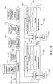
- FIG. 1 comprising an illustrative example of a system incorporating an application architecture embodying the present invention.
- a first application server personal computer (PC) 100 and a second application server PC 102 collectively and cooperatively execute a distributed multi-layered supervisory process control and manufacturing information application comprising a first portion 104 and second portion 106.
- the application portions 104 and 106 include device integration application objects PLC1 Network and PLC1, and PLC2Network and PLC2, respectively.
- the PLCxNetwork device integration objects facilitate configuration of a data access server (e.g., OPC DAServers 116 and 118).
- the PLC1 and PLC2 device integration objects access data locations within the buffers of the OPC DAServers 116 and 118.
- the data access servers 116 and 118 and the device integration objects cooperatively import and buffer data from external process control components such as PLCs or other field devices.
- the data buffers are accessed by a variety of application objects 105 and 107 executing upon the personal computers 100 and 102. Examples of application objects include, by way of example, discrete devices, analog devices, field references, etc.
- application engines host the application objects (via a logical grouping object referred to herein as an "area".
- the engines are in turn hosted by platform objects at the next lower level of the supervisory process control and manufacturing information application.
- the application portions 104 and 106 are, in turn hosted by generic bootstrap components 108 and 110. All of the aforementioned components are described herein below with reference to FIG. 2 .
- the multi-layered application comprising portions 104 and 106 is communicatively linked to a controlled process.
- the first application server personal computer 100 is communicatively coupled to a first programmable logic controller 112
- the second application server personal computer 102 is communicatively coupled to a second programmable logic controller 114.
- the depicted connections from the PCs 100 and 102 to the PLCs 112 and 114 represent logical connections. Such logical connections correspond to both direct and indirect physical communication links.
- the PLC 112 and PLC 114 comprise nodes on an Ethernet LAN to which the personal computers 100 and 104 are also connected.
- the PLCs 112 and 114 are linked directly to physical communication ports on the PCs 100 and 102.
- the PCs 100 and 102 execute data access servers 116 and 118 respectively.
- the data access servers 116 and 118 obtain/extract process information rendered by the PLC's 112 and 114 and provide the process information to application objects (e.g., PLC1Network, PLC1, PLC2Network, PLC2) of the application comprising portions 104 and 106.
- application objects e.g., PLC1Network, PLC1, PLC2Network, PLC2
- the data access servers 116 and 118 are, by way of example, OPC Servers. However, those skilled in the art will readily appreciate the wide variety of custom and standardized data formats/protocols that are potentially carried out by the data access servers 116 and 118.
- the exemplary application objects through connections to the data access servers 116 and 118, represent a PLC network and the operation of the PLC itself.
- the application objects comprise a virtually limitless spectrum of classes of executable objects that perform desired supervisory control and data acquisition/integration functions in the context of the supervisory process control and manufacturing information application.
- the supervisory process control and management information application is augmented, for example, by a configuration personal computer 120 that executes a database (e.g., SQL) server 122 that maintains a supervisory process control and management information application configuration database 124 for the application objects and other related information including templates from which the application objects are rendered.
- the configuration database 124 also includes a global name table 125 that facilitates binding location independent object names to location-derived handles facilitating routing messages between objects within the system depicted in FIG. 1 .
- the configuration PC 120 and associated database server 122 support: administrative monitoring for a multi-user environment, revision history management, centralized license management, centralized object deployment including deployment and installation of new objects and their associated software, maintenance of the global name table 125, and importing/exporting object templates and instances.
- IDE Integrated Development Environment
- DCOM distributed component object model
- the IDE is a utility from which application objects are configured and deployed to the application server PCs 100 and 102. Developers of a supervisory process control and manufacturing information application, through the IDE, carry out a wide variety of system design functions including: importing new object and template types, configuring new templates from existing templates, defining new application objects, and deploying the application objects to the host application engines (AppEngine1 or AppEngine2 in FIG. 1 ) on the application server PCs 100 and 102.
- the exemplary supervisory control network environment depicted in FIG. 1 also includes a set of operator stations 130, 132, and 134 that provide a view into a process or portion thereof, monitored/controlled by the supervisory process control and management information application installed and executing as a set of layered objects upon the PCs 100 and 102.
- a RawMaterial PC 130 provides a representative view enabling monitoring a raw materials area of a supervised industrial process.
- a ProductionPC 132 presents a representative view of a production portion of the supervised industrial process.
- a FinishedProductPC 134 provides a representative view of an area of a production facility associated with finished product.
- Each one of the operator stations 130, 132, and 134 includes a bootstrap host for each of the particular operator station platforms.
- Each one of the operator stations 130, 132, and 134 includes a view engine that process graphics information to render a graphical depiction of the observed industrial process or portion thereof.
- FIG. 1 is merely an example of a multi-layered hierarchical architecture for a supervisory process control and manufacturing information system.
- the present invention is not limited to the particular disclosed application/system.
- the multi-layered application approach is applicable, at a lower control level, to a distributed control system (DCS) application or a programmable logic controller (PLC) application.
- DCS distributed control system
- PLC programmable logic controller
- FIG. 1 is presented as a logical view of the interrelations between installed software and physical computing hardware and is not intended to designate any particular network topology. Rather the present invention is suitable for a virtually any network topology.
- the present invention is applicable to a control application running on a single computer system linked to a controlled process.
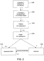
- FIG. 2 a class diagram depicts the hierarchical arrangement of layered software associated with a computer executing at least of portion of a supervisory process control and manufacturing information application.
- Each computer executes an operating system 200, such as MICROSOFT'S WINDOWS at a lowest level of the hierarchy.
- the operating system 200 hosts a bootstrap object 202.
- the bootstrap object 202 is loaded onto a computer and activated in association with startup procedures executed by the operating system 200.
- the bootstrap object 202 must be activated before initiating operation of the platform class object 204.
- the bootstrap object 202 starts and stops the platform class object.
- the bootstrap object 202 also renders services utilized by the platform class object 204 to start and stop one or more engine objects 206 hosted by the platform class object 204.
- the platform class object 204 is host to one or more engine objects 206.
- the platform class object 204 represents, to the one or more engine objects 206, a computer executing a particular operating system.
- the platform class object 204 maintains a list of the engine objects 206 deployed on the platform class object 204, starts and stops the engine objects 206, and restarts the engine objects 206 if they crash.
- the platform class object 204 monitors the running state of the engine objects 206 and publishes the state information to clients.
- the platform class object 204 includes a system management console diagnostic utility that enables performing diagnostic and administrative tasks on the computer system executing the platform class object 204.
- the platform class object 204 also provides alarms to a distributed alarm subsystem.
- the engine objects 206 host a set of application objects 210 that implement supervisory process control and/or manufacturing information acquisition functions associated with an application.
- the engine objects 206 initiate startup of all application objects 210.
- the engine objects 206 also schedule execution of the application objects 210 with regard to one another with the help of a scheduler object.
- Engines register application objects with a scheduler for execution.
- the scheduler executes the application objects relative to other application objects based upon the configuration specified by an engine.
- the engine objects 206 monitor the operation of the application objects 210 and place malfunctioning ones in a quarantined state.
- the engine objects 206 support check pointing by saving/restoring changes to a runtime application made by automation objects to a configuration file.
- the engine objects 206 maintain a name binding service that bind attribute references (e.g., tank1.value.pv) to a proper one of the application objects 210.
- the engine objects 206 ultimately control how execution of application objects will occur. However, once the engine objects 206 determine execution scheduling for application objects 210, the real-time scheduling of their execution is controlled by a scheduler 208.
- the scheduler supports an interface containing the methods RegisterAutomationObject() and UnregisterAutomationObject() enabling engine objects 206 to add/remove particular application objects to/from the schedulers list of scheduled operations.
- the application objects 210 include a wide variety of objects that execute business logic facilitating carrying out a particular process control operation (e.g., turning a pump on, actuating a valve), and/or information gathering/management function (e.g., raising an alarm based upon a received field device output signal value) in the context of, for example, an industrial process control system.
- Examples of application objects include: analog input, discrete device, and PID loop.
- a class of application objects 210 act upon data supplied by process control systems, such as PLCs, via device integration objects (e.g., OPC DAServer 118). The function of the integration objects is to provide a bridge between process control/manufacturing information sources and the supervisory process control and manufacturing information application.
- the application objects 210 include an application interface accessed by engine objects and schedulers.
- the engine objects access the application object interface to: initialize an application object, startup an application object, and shutdown an application object.
- the schedulers use the application object interface to initiate a scheduled execution of the application object.
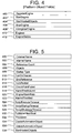
- FIG. 3 depicts a common object primitive definition.
- the common primitive is incorporated into all the application objects (i.e., platform, application engine, scheduler, application, etc.).
- a scripts attribute 300 is used to keep track of scripts that are associated with an application object.
- the scripts attribute 300 includes scripts inherited from templates as well as scripts created specifically for the particular object type.
- a UDA (user defined attribute) attribute 302 references inherited and new user defined attributes for an object.
- An alarm mode attribute 304 indicates whether an alarm is enabled and the extent to which it is enabled.
- a based on attribute 306 identifies a particular base template from which an object was derived.
- Attribute 308 stores a string identifying attribute names in an object.
- a contained name attribute 310 identifies the name assigned to an object within a container. For example, an object may correspond to a "level" contained within a "reactor" object.
- a deployed version attribute 312 stores an integer identifying a version for a deployed object.
- a derived from attribute 314 identifies the actual template from which an object was derived. The contents of the derived from attribute 314 differ from the contents of the based on attribute 306.
- the based on attribute 306 is the base template from which this object was derived from.
- the derived attribute 314 is the immediate template from which this object was created. For example for a hierarchy of templates as follows:
- a relative execution order attribute 316 identifies another object with which a present object has a relative execution order relation. In addition to identifying another object, attribute 316 identifies the relative order of execution of the objects (e.g., none, before, after, etc.). The relative execution order information is utilized to schedule execution of application objects.
- a hierarchical name attribute 318 stores a full name for an object including any of the containers of the object (e.g., Reactor1.level).
- An IsTemplate attribute 320 indicates whether the object is a template or an object instantiated from a template.
- An AlarmInhibit attribute 322 within an area or container object provides cutout functionality to inhibit alarms for all objects within an area or container.
- An alarm mode attribute 324 specifies the current alarm mode of an object. The mode is based upon the object's commanded mode if area and container are enabled. Otherwise, the most disabled state of the container or parent area applies.
- Alarm Mode Command attribute 326 specifies the object's currently commanded alarm mode.
- the illustrative example of the present invention supports an object hierarchy.
- Objects specify such hierarchy in the context of a plant/model view in an area attribute 328 that specifies an area to which an object belongs.
- a container attribute 330 specifies a container that contains the object.
- a hosting relationship exists among various deployed objects.
- a platform hosts an engine, and an engine (via an area) hosts application objects.
- a host attribute 338 identifies an object's host.
- a category attribute 332 specifies a class of objects with which the object is associated, thereby facilitating organizing objects according to local associations and/or functionality.
- the value is one of the categories named in a category enumeration attribute 334.
- An error attribute 336 identifies errors generated by the object.
- An InAlarm flag 340 stores a Boolean flag indicating whether an alarm exists in an object. The flag is true only if a Scan State flag 342 is true (the object is on scan) and the object's alarms are enabled. The scan state of an object is changed through a Scan State Command 344 that signals whether to take the object on/off scan.
- a security group 346 enables designating a particular security group for the object to limit access/use of the object to particular classes of users.
- a description attribute 348 provides an area to store a short description of an object.
- a tag name attribute 350 specifies a unique tag for an object.
- a warnings attribute 352 lists any warnings rendered by an object.
- a set of object type-specific attributes are described herein below beginning with attributes for a platform primitive with reference to FIG. 4 .
- the attributes identified in FIG. 4 relate to supporting the object/engine/platform hosting hierarchy. While not identified in FIG. 4 , a set of attributes are provided through the platform primitive enabling platform objects to monitor/report computer device statistics. Other attributes included in the exemplary platform primitive, but not included in FIG. 4 , concern detecting and reporting alarms associated with computer device statistics and storing the statistics.
- a RegisterEngine attribute 400 stores a command to register a new engine.
- the RegisterEngine attribute 400 is used at deployment time to register an engine with a host platform.
- a StartEngine attribute 402 stores a command to start a particular deployed engine on the platform.
- a StartHostedObjects attribute 404 stores a command passed to the platform to start all hosted engines that are start auto and start semi-auto type engines.
- a StopEngine attribute 406 stores a command to stop a particular deployed engine on the platform.
- An UnRegisterEngine attribute 308 stores a command to un-deploy a previously deployed engine on the platform.
- An Engines attribute 410 stores a list of all engines deployed on the platform.
- An EngineStates attribute 412 stores a list of the current operational states of all engine objects hosted by the platform.
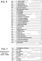
- FIG. 5 summarizes a set of attributes associated with an engine primitive.
- An external name attribute 500 stores a string used for external reference.
- An internal name attribute 502 stores a string used for internal reference.
- a reference count attribute 504 stores the number of objects referencing the engine object. When the number of references reaches zero, there are no clients, external to the engine, referencing any automation object attributes on the engine. This helps operators determine the impact (how many clients will be affected) of stopping the engine.
- An object attribute 506 is an array comprising a set of all objects hosted by the engine object.
- a startup type attribute 508 identifies how an engine object will be started (e.g., automatic, semi-automatic, manual).
- a CanGoOnscan attribute 510 indicates whether an engine object can be placed on-scan.
- a BindReference attribute 512 is a command used to resolve references (e.g., pump001.inlet.PV) to handles. These handles are used to locate objects at runtime by the messaging infrastructure.
- An AutoRestart attribute 514 stores a Boolean value indicating whether the engine object should be automatically restarted upon detection of a failure.
- a CheckpointFailedAlarm attribute 516 stores a value indicating whether a last attempt to checkpoint hosted objects had failed during a last attempt.
- An AlarmThrottleLimit attribute 518 stores a value, in alarms per second raised by an engine object before throttling of alarms generated by objects on the engine will occur.
- An EngineAlarmRate attribute 520 indicates the number of alarms registered on an engine during a last complete scan.
- An AlarmsThrottled attribute 522 indicates that an engine object throttled alarms during the last scan.
- a set of attributes is provided to handle script execution.
- a ScriptExecuteTimout attribute 524 stores a time limit for a synchronous script to complete execution before an alarm is raised by an engine object.
- a ScriptStartupTimeout attribute 526 stores a time limit for a synchronous script to startup before an alarm will be raised.
- a ScriptShutdownTimout attribute 528 stores a time limit for a synchronous script to shutdown before an alarm will be raised.
- a PublisherHeartbeat attribute 530 stores a value corresponding to the number of seconds an engine object will wait for a heartbeat message from another engine object before it assumes the engine has failed.
- a Process ID 532 identifies a unique identification assigned to an engine process.
- An engine object also contains a set of command attributes associated with managing application objects.
- a CreateAutomationObject attribute 534 is a command attribute for creating an application object.
- a DeleteAutomationObject attribute 536 is a command attribute for deleting an application object.
- a StartHostedObjects attribute 538 is a command attribute for starting hosted application objects.
- Each scheduler object includes internal and external name attributes 600 and 602.
- a StatsAvgPeriod 604 stores a value representing the averaging period for the scheduler acquiring statistics stored within the attributes described herein below.
- a CheckpointPeriodAvg attribute 606 identifies the current average of times between checkpoints during the current averaging period.
- An ExecutionTimeAvg attribute 608 stores a value representing the amount of time to execute all the objects per scan cycle.
- a HousekeepingTimeAvg attribute 610 stores a value corresponding to the average time per cycle to complete housekeeping operations.
- a TimeIdleAvg attribute 612 stores a value representing the average idle time per period.
- a TimeIdleMax attribute 614 stores a value representing the maximum idle time recorded.
- a TimeIdleMin attribute 616 stores a value representing the minimum idle time recorded.
- An InputMsgSizeAvg attribute 618 stores an average input message size over the averaging period.
- An InputMsgsProcessedAvg attribute 620 stores a value representing the total volume of messages processed, in bytes, per scan cycle during the averaging period.
- An InputMsgsQueuedAvg attribute 622 stores the average number of messages queued per scan cycle during the averaging period.
- An InputMsgsQueuedMax attribute 624 stores the maximum average stored in attribute 622 since the last time the statistics attributes were reset.
- An InputQueueSizeMaxAllowed attribute 626 stores the maximum allowed size of queued messages in a network message exchange input queue.
- An InputQueueSizeAvg attribute 628 stores an average size of the input queue in bytes during the averaging period.
- An InputQueueSizeMax attribute 630 stores the maximum average stored in attribute 628 since the last time the statistical attributes were reset.
- a TimeInputAvg attribute 632 stores a value representing the average time required, during the current period, to process an input message.
- An ObjectCnt attribute 634 stores a count value corresponding to the current number of application objects currently being handled by a scheduler object.
- An ObjectsOffScanCnt attribute 636 indicates the number of application objects that are currently off-scan.
- a TimeOutputAvg attribute 638 stores an average amount of time required to process output message during a cycle.
- a StatsReset attribute 640 indicates an request to reset the statistical attributes described for the scheduler that are not regularly reset (e.g., maximum values).
- a ScanCyclesCnt attribute 642 stores a value indicating the number of cycles since a last resetting of the attributes through the StatsReset attribute 640.
- a ScanOverrunsCnt attribute 644 indicates the number of times, since a last StatsReset, that a scan cycle ended without completing a scan of all objects.
- a ScanOverrunsConsecutiveCount 646 stores a current number of consecutive cycles where an overrun occurs.
- a ScanOverrunHighLimit attribute 648 stores a high alarm limit for consecutive overruns to trigger an alarm stored in a ScanOverrunCondition attribute 650.
- a ScanPeriod 652 stores a value representing the cycle time for the scheduler.
- attributes associated with particular object types are not limited to the particular object primitive types. In fact, all object types comprise at least two of the above-described primitives. All object types utilize the common object primitive.
- a platform object includes the attributes of the scheduler, engine and platform primitives described above.
- An engine object includes the attributes of the scheduler, and the engine primitives.
- a set of primitives is associated with an application object.
- Each type of application object has its own set of primitives.
- the primitives contain the business specific logic and the set of attributes that are unique to the function of the primitives. These primitives can be reused across different application object types.
- a primitive 700 labeled AnalogDevice attributes contains a set of analog device specific attributes in which clients would be interested.
- a PV.Input 701 is a primitive that reads, via a device integration object (e.g., PLC1), the data from a field device.
- a PV.Output 702 is a primitive that writes, via a device integration object, data to the field.
- a Scaling 703 is a primitive that performs linear or square root scaling of the data read from the input primitive (PV.Input 701).
- a LevelAlarms 704 is a primitive that generates alarms if a process variable in the AnalogDevice primitive 700 exceeds or is below configured values.
- a PV.RoC 705 is a primitive that generates alarms if a PV increases or decreases faster than a preset limit.
- a SP 706 is a primitive that clients write to when they want to modify the value to which the PV.Output 702 writes.
- a PVDev 707 is a primitive that is used to generate an alarm if a value read in from a field device (via primitive 701) deviates from a value written to the field device (via primitive 702) by a certain amount.
- a CtrlTrack 708 is a primitive that is used to enable the setpoint and PV primitives to track changes driven from the external device.
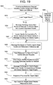
- FIG. 8 a sequence diagram depicts steps for the starting and stopping an application embodying a hierarchical hosting relationship.
- a bootstrap process on a computer system issues a start platform request to a loaded platform object.
- the platform process issues a call to the bootstrap interface requesting the bootstrap to start all the application engines hosted by the platform object.
- the bootstrap process creates an application engine object having the attributes discussed hereinabove.
- the application engine process starts all of its hosted application objects.
- the application engine also registers the hosted application objects with a scheduler process during stage 808. Registering an application object adds that application object to the set of application objects that the scheduler scans during each scan cycle.
- the application engine issues a command to the scheduler to begin executing/scanning the started and registered application objects.
- the scheduler executes the registered application objects. Such execution is performed periodically during each scan cycle.
- the scheduler continues to periodically scan the registered application objects in accordance with a supervisory process control and manufacturing information system application until receiving a shutdown command.
- the bootstrap process issues a shutdown command to the platform process in response to an operating system shutdown command.
- the platform process returns a stop engine command to the bootstrap to commence shutting down all engines hosted by the platform process.
- the bootstrap issues a request to the application engine to stop. The bootstrap will wait for the application engine to stop. However, after a period, if the application engine has not stopped, the bootstrap will request the operating system to shut down the application engine process.
- the application engine issues a command to the scheduler to un-register the engine's hosted application objects. Furthermore, in an embodiment of the invention, the engine requests to its hosted application objects to shut down. However, in alternative embodiments of the invention the shutdown request is issued by the scheduler in response to the un-register command.
- the engine objects and platform objects communicate with the bootstrap process and handle aspects of the supervisory process control and manufacturing information application relating to physical computing device configurations upon which the application executes.
- the application objects themselves only communicate with the engine and scheduler according to a platform-independent interface.
- the one or more engine objects hosting the application objects insulate the application objects from characteristics of the computer systems upon which the application objects execute.
- the application objects execute independently of the physical computing device configurations.
- the application objects though constrained to execute on a same engine with other application objects designated within a same area, are not constrained by any requirement to execute upon a particular one of multiple capable engines and/or platforms within a system. Thus, moving an area comprising a set of application objects is performed with minimal interruption to the execution of other application objects running on the affected engines.
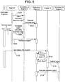
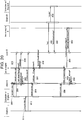
- FIG. 9 a sequence diagram illustrates the operational independence of an application object with regard to its engine object host, and the ability to re-deploy an application object upon another host engine.
- an engine A issues a start command to a scheduler A to commence periodic execution/scanning of an application object A.
- the scheduler A periodically activates the application object A to perform its business logic in association with an application comprising multiple application objects.
- an application engineer decides to migrate the application object A to an engine B on a different computer platform.
- One reason to make such a change is to reduce computational load on a computer device as a system grows.
- the user issues a request to the engine A to remove application object A during stage 904.
- the engine A issues a request to the scheduler A to stop scanning the application object A.
- the engine A issues a command to the application object A to shut down. The operation of the engine A and scheduler A is otherwise unaffected by the removal of application object A.
- the application is spread across multiple computing devices, and each computing device is equipped with the platform, engine and scheduler objects of the application hierarchy that facilitate executing application objects.
- the replication of lower-level hosting functionality across multiple hardware platforms provides a degree of platform independence that enables relocating an application object without affecting the operation of the application.
- the user adds application object A to engine B on a different computer.
- the engine B initializes the newly added application object A.
- the initialization stage 912 includes, for example, any custom initialization performed by an application object before starting the application object (e.g., initialization of class variables, caching interfaces used by the application object, etc.).
- the engine B issues a start command to the application object A.
- Engine B registers the executing application object A with a scheduler B on the new computing platform during stage 916. Thereafter, at stage 918 the scheduler B periodically prompts the application object A to execute its business logic. The results of executing application object A are rendered both locally and over a network connecting the engines. Thus, re-locating application object A to engine B does not affect data access concerning application object A.
- the application objects reference other objects by logical name rather than physical address.
- communications between application objects within a same application, as far as the application objects are concerned are insulated from the underlying physical configuration of a network containing the application object.
- a component of the application referred to as message exchange, embedded within the platform and engine objects enables application objects to retrieve (get) and send (set) data from/to other objects located anywhere within a network executing the distributed application.
- message exchange is a peer-to-peer communication infrastructure that enables specifying a target by logical name rather than physical network address. The application objects are thus permitted to carry out communications without regard to the physical location of an intended recipient of a data request.
- the message exchange is divided between a local message exchange (LMX) carried out by an application engine and a network message exchange (NMX) carried out by a platform to enable named requests to be communicated between computing devices connected over a network for carrying out a distributed application.
- LMX local message exchange
- NMX network message exchange
- the LMX and NMX functionality is carried out by the engines. This arrangement avoids extra, inter-process communications required in the event that the platform object carries out NMX.
- the LMX incorporated into the engine objects provides services enabling application objects to access data maintained as attributes on other objects.
- application objects specify a string representing a piece of data associated with an object (e.g., an attribute specified in the form of "ObjectB.AttributeA").
- LMX locates the data associated with the object (potentially requesting NMX services provided by the platform to access a target object located on another computing device in a network).
- LMX returns the data, associated with the object, to the application object that requested the data.
- the message exchange guarantees certification of message delivery. Therefore, when application objects send messages to other application objects they receive confirmation that the target of the message received or did not receive the message.
- the LMX of the application engine includes, by way of example, a set of interfaces.
- the set of interfaces comprises: IMxSupervisoryConnection and IMxUserConnection.
- the IMxSupervisoryConnection interface defines methods used by application objects to access information from physical devices in a plant.
- the methods used on this interface comprise: SupervisoryRegisterReference, SupervisoryGetAttribute, and SupervisorySetAttribute.
- the SupervisoryRegisterReference method is called by application objects to inform message exchange that a request to access a value of an attribute is forthcoming.
- the SupervisorySetAttribute method is used by application objects to direct message exchange to modify the value of the attribute specified in a previous SupervisoryRegisterReference call.
- the SupervisoryGetAttribute method is used by application objects to direct message exchange to retrieve the value of the attribute specified in a previous SupervisoryRegisterReference call.
- the IMxUserConnection interface defines methods used by applications to visualize data retrieved from physical devices in a plant.
- the methods used on this interface comprise: UserRegisterReference, UserGetAttribute, and UserSetAttribute. These methods are very similar to the methods of the IMxSupervisoryConnection interface described hereinabove.
- One difference is that the methods of the IMxUserConnection interface methods cater to user interface clients by allowing data updates via a callback mechanism instead of a polled mechanism utilized by the IMxSupervisoryConnection.
- An MxReference structure is a MICROSOFT Component Object Model (COM) object that implements an interface IMxReference, identifies an attribute of an object whose value is to be accessed by application objects, and is passed into the methods SupervisoryRegisterReference, and UserRegisterReference.
- the MxReferenceHandle (an integer value) is used by message exchange to provide application objects a location-transparent means of retrieving a value referred to by an MxReference.
- the MxReferenceHandle is returned to application objects by the message exchange on successful completion of a SupervisoryRegisterReference or UserRegisterReference call.
- the MxReferenceHandle is passed in, by application objects, to method calls for getting and setting attributes such as: UserSetAttribute, UserGetAttribute, SupervisorySetAttribute and SupervisoryGetAttribute.
- An MxHandle structure identifies a property of an object's attribute.
- the MxHandle identifies a platform and an engine to which the object belongs.
- the MxHandle comprises two structures: an MxAutomationObjectHandle and an MxAttributeHandle.
- the MxAutomationObjectHandle is the data structure used to represent the location of the object within the overall system.
- the MxAttributeHandle data structure is used to identify the property of an attribute within the object.
- the MxAttributeHandle structure is used, internally, by message exchange to quickly locate an attribute of an object.
- the MxAttributeHandle data structure includes seven fields: primitiveID, attributeID, propertyID, index1, index2, index3 and signature.
- the primitiveID field identifies a primitive within an automation object.
- a primitive is a helper object that performs a specific operation in, for example, an application object.
- the attributeID identifies a particular attribute within an identified primitive.
- a propertyID identifies a property of an attribute.
- Index fields 1, 2 and 3 provide indexes into up to a three-dimensional array.
- a signature field stores a checksum value derived from the content of the MxAttributeHandle to prevent configuration mismatches.
- the message exchange in an embodiment of the present invention, includes additional data structures and interfaces. Such additional interfaces and structures will be known to those skilled in the art. It is further noted that the present invention is not limited to systems that utilize message exchange to provide a hardware/deployment independent messaging service for inter-object communications for a set of application objects within a supervisory process control and manufacturing information application.
- the associations enable a configuration component, referred to herein as the Integrated Development Environment (IDE) to filter and display a set of related objects in a variety of views including at least a (logical) model view and a (physical computing) deployment view.
- IDE Integrated Development Environment
- the IDE through its displayed views of an application configuration, enables a user to design and deploy an application in a computer network comprising multiple computing devices.
- the application configurations are stored as "packages" within the configuration database 124.
- a package framework subsystem provides an interface enabling the IDE to store and retrieve the objects of the packages.
- the package framework employs a relational database to store package data and knowledge regarding the objects' associations/relationships with other objects.
- the IDE queries the package framework to deliver a list of objects based on a designated association with regard to an object. For example, the IDE can request the package framework to retrieve from a package the objects hosted by a named engine.
- a host relationship is used at runtime to indicate where an object executes. Furthermore, an object may not be deployed unless its host is deployed.
- An application object is hosted by an area object, an area object is hosted by an engine object, and an engine object is hosted by a platform object.
- An area relationship establishes a logical grouping of objects and provides a means for collecting events and alarms raised by objects grouped under the area.
- a container relationship specifies a loose coupling between two objects and is only meaningful in the context of the application logic.
- a valve that acts as an inlet is assigned the alias "inlet” and receives the hierarchical name of "Tank.Inlet.”
- An object's engine is the actual engine that executes the object.
- An object's platform is the one and only platform object running on a computer device upon which the object is deployed. An object may have all five of these relationships, but only one object may be associated to any one of these relationships.
- an application object can be assigned to one and only one area.
- a model view depicts the application in terms of logical associations between plant/process equipment within a controlled plant process - e.g., a representation of a physical plant layout.
- a deployment view depicts the physical computer devices and assignment of instantiated objects identified in the model view to the computer devices and engines executing upon the computer devices.
- a derivation view depicts the sources (inherited property relationships from base template to instance) of objects instantiated from templates to carry out the functionality of the model view elements.
- FIG. 1 shows, by way of example, an application physically deployed to two application server computers 100 and 102.
- an application is presented to users by visually depicting the role of application objects in carrying out supervisory process control and/or extracting manufacturing information according to the application.
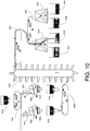
- FIG. 10 a plant process application is depicted, in a plant model, according to the roles of application objects in the plant process.
- This illustrative example is scaled down for purposes of illustratively depicting an exemplary embodiment of the invention.
- the present invention is applicable to a wide variety of industrial/plant monitoring/control applications that are far more complex than this example.
- a hopper H1 1000 having a controlled outlet valve delivers raw product to a conveyor C1 1002 that is controllable to travel left, right, or be disabled.
- the raw product is dumped by the conveyor C1 1002 into a mixer M1 1004 and a mixer M2 1006.
- the raw product is allowed to pass into the mixers by opening valve V1 1012 and V2 1014 of mixer M1 1004 and mixer M2 1006, respectively.
- the mixer M1 1004 and mixer M2 1006 include a controllable agitator A1 1008 and A2 1010 respectively.
- the mixed product drops into hoppers H2 1016 and H3 1018.
- the hoppers H2 1016 and H3 1018 are selectively opened to allow the mixed product to fall upon a conveyor C2 1020 that either travels right or is disabled.
- the conveyer C2 1020 drops the mixed product onto an elevator E1 1022.
- the elevator E1 1022 deposits the mixed product onto a conveyer C3 1024 that travels right.
- the conveyor C3 1024 deposits the material onto a distribution conveyor C4 1026 that is capable of traveling both left and right thereby distributing the mixed product between a first bi-state door D1 1028 and a second bi-state door D2 1030.
- the door D1 1028 is controllable to direct finished product into either bin B1 1032 or B2 1034.
- the door D2 1030 is controllable to direct finished product into either bin B3 1036 or bin B4 1038.
- the application objects corresponding to the sensors and controlled components are logically grouped within areas.
- the logical grouping of application objects is exploited during runtime to provide a uniform treatment of particular application objects for alarm and event management. For example, all alarms in a particular area can be disabled by a single attribute designation within the area object.
- the compatibility of the host area and hosted objects is determined by checking the "required host features" of the hosted object and the "supported features" specified by the hosting area object. These object attributes are established when the objects are built. If the "required host features" are met by the "supported features," then the host assignment is completed by assigning appropriate values to hosted objects.
- An object is placed within an area by designating the area name in the area attribute 328 of the common primitive of an application or area object.
- Area objects include the following attributes that facilitate the above-described functionality: alarm information, disable all alarms, disable the display of all alarms, sub-area list.
- a raw material store area 1100 includes the hopper H1 1000.
- a production area 1102 includes the conveyor C1 1002, a line 1 area 1104 including the mixer M1 1004, valve V1 1012, and hopper H2 1016, and a line2 area 1106 including the mixer M2 1006, valve V2 1014, and hopper H3 1018.
- a distribution area 1108 includes the conveyor C2 1020, the elevator E1 1022, the conveyer C3 1024, conveyor C4 1026, bi-state door D1 1028 and bi-state door D2 1030.
- a finished product store area 1110 includes bins B1 1032, B2 1034, B3 1036 and bin B4 1038. The set of sub-areas are grouped under a single process plant area 1120.
- a configuration utility interface that displays the application components according to these two alternative views.
- FIG. 12 a partially completed model view user interface generated by a configuration utility depicts an area hierarchy represented in the form of a tree.
- the tree structure presents a high-level model view of the areas designated in a process plant depicted in FIG. 11 .
- This model view is incomplete since it does not identify the application objects grouped within the identified areas and containment relationships for application objects.
- a process plant node 1200 corresponding to the process plant area 1120 is designated at the highest level of the hierarchical area representation.
- RawMaterialStore node 1202, Production node 1204, Distribution node 1206 and FinishedProductStore node 1208 correspond to the raw material store area 1100, the production area 1102, a distribution area 1108 and a finished product store area 1110 respectively.
- a line 1 node 1210 and a line 2 node 1212 branching from Production node 1204 correspond to the line1 area 1104 and line2 area 1106 grouped within the production area 1102 in FIG. 11 .
- This view enables a technician to quickly identify and specify logical groupings for defining policies governing application objects such as alarming behaviors, etc.
- FIG. 10 Before describing an expanded version of the model view of FIG. 12 identifying application objects and compounds within the identified areas, derivation of objects from templates is discussed.
- Each of the components identified in FIG. 10 corresponds to an application object.
- application objects are instantiated from object templates.
- a derivation view represents all the types of templates from which application objects specified by a current model for an application are derived.
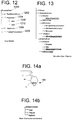
- FIG. 13 an exemplary derivation view rendered by a derivation view generated is illustratively depicted.
- the user derives from a $DiscreteDevice base template a $Valve, a $SliceGate, a $Agitator, and a $Conveyor custom application object template type.
- the user further defines a $SingleDirectionConveyor, a $BiDirectionalConveyor, and an $Elevator template type.
- a $UserDefined base template the user derived a $Vessel application object template.
- the $Vessel template is further refined to derive a $Hopper and a $Bin application object.
- the base templates occupy the highest levels of the hierarchical derivation tree that is rendered by a configuration view generator based upon a user's designation of particular templates.
- Object templates derived from the base templates are identified by branches leading from the base template nodes. As depicted in FIG. 13 , it is possible to derive objects from other derived objects. In such cases, the children inherit the designated characteristics of their parent templates.
- the derivation relationship between a child and its parent template is registered in the derived from attribute 314 of the template object.
- Application object containment (specified in container attribute 330 of an application object), and the creation of compound object templates from a set of previously defined object templates is another aspect of the template architecture disclosed herein.
- containment is limited to same object types.
- area objects can only contain area objects and application objects can only contain other application objects.
- Objects containing other objects are referred to herein as "compounds.”
- Objects that exist solely to contain other objects are referred to as "composites.”
- FIGs. 14a and 14b an example is provided of a compound application object template - in this case a $MixerVessel compound object template that includes a valve object that is assigned the tag name "inlet”, an agitator that continues to carry the tag name of "agitator,” and a mixer that has been assigned the tag name "vessel.”
- the contained name attribute 310 of the templates corresponding to each of these three contained objects.
- the full hierarchical tag name (e.g., MixerVessel.Inlet) is stored in the hierarchical name attribute 318 for each of the three contained objects.
- the container attribute 330 for each contained object is assigned the string "MixerVessel.”
- FIG. 14a schematically depicts a portion of the process plant depicted in FIG.
- FIG. 14b A model view of the compound template showing the containment relationship between the $MixerVessel application object template and its contained (renamed) application objects is depicted in FIG. 14b .
- all application objects contained within a compound application object designate a same host in attribute 338 (and by requirement a same area in attribute 328.
- This containment hierarchy applicable to other objects as well (subject to any deployment restrictions), assists system developers in developing systems by supporting the creation of logical building blocks (comprising many smaller application objects) from which applications can be built.
- a "contain” function supported by the IDE facilitates establishing containment relationships between objects via a graphical user interface "drag and drop” operation.
- a developer selects the source application object displayed on a user interface, drags the source application object on top of the target (container) object, and then drops the source application object on the target application object.
- the IDE confirms the compatibility between the two objects (i.e., they are both application objects) sets the host, area and container attributes in the source object.
- the area attribute 328 is set to the target object's area
- the host attribute 338 is set to the target's host
- the container attribute 330 is set to the target object's name.
- the contained name attribute 310 and the hierarchical name attribute 318 of the source are also filled in with names provided by the developer.
- the $MixerVessel compound application object template is assigned a branch under the $UserDefined base template node and specifies the contained relationships between the application object template elements of the compound. Furthermore, a $MixerVessel.Inlet template derived from $Valve is placed under the $Valve template node. A $MixerVessel.Vessel template derived from $Vessel is placed under the $Valve template node. A $MixerVessel.Agitator template derived from $Agitator is placed under the $Agitator template node.
- the containment relationship is registered by specifying the $MixerVessel template object in the container attribute 330 in each of the compound elements. The containment relationship is indicated in the derivation view tree of FIG. 13 by a "$MixerVessel" preamble in the $MixerVessel.Inlet, $MixerVessel.Agitator, and $MixerVessel.Vessel object template representations within the derivation view tree.
- Attribute locking and its effect upon change propagation in templates are yet other aspects of the derivation architecture of the exemplary configuration utilities disclosed herein.
- the derivation architecture enables information within an object template to be propagated to derived objects or alternatively a default value is specified for a derived template that can be overridden by a developer.
- propagation is affected automatically by storing a reference to a parent's copy of a locked attribute.
- An attribute in a template or instance can be unlocked, locked in parent, or locked in me. Both templates and instances can have unlocked attributes.
- An unlocked attribute is read-write, and the object has its own copy of the attribute value - i.e., it is not shared by derived objects.
- a template, but not an instance can have a locked in me attribute status. In the case of a locked in me attribute, the value is read-write. Derived objects do not get their own copy of the attribute value, but instead share the locked value by reference to an ancestor where the attribute is locked. The status of the attribute in the children of a locked in me attribute is "locked in parent.” Thus, changes to the value of a locked in me template attribute propagate to all children.
- Both templates and instances can have a locked in parent attribute.
- a locked in parent attribute is read-only.
- the interface for getting and setting a locked status of an attribute is exposed to configuration clients.
- the client obtains a reference to the attribute and sets its locked status. Whether a change to an attribute is permitted and/or propagated to derived children is based upon whether a particular attribute in a template is locked.
- Locking an attribute has two consequences. First, a locked in parent attribute cannot be modified in a derived template or instance. Second, a locked in me attribute in a template can be changed, and the change is cascaded down through all templates and instances derived from the template containing the locked attribute. On the other hand, if an attribute is not locked, then the attribute specifies a default value that can be overridden in a derived template. Furthermore, if the value of a non-locked attribute is changed, then the change is not cascaded to derived templates.
- the application object instances are created from the templates according to the proposed supervisory process control and manufacturing information application.
- the following application objects are rendered:
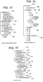
- a hardware derivation view depicts the sources of engine and platform objects from object templates. Such a view is beneficial when deciding where to distribute or re-locate areas that have particular engine and/or platform requirements.
- Node 1500 corresponds to a WINDOWS operating system-based platform template.
- Node 1510 corresponds to an application engine template.
- Node 1520 corresponds to a view engine template.
- a set of view engine instances branch from node 1520 and correspond to the view engines depicted in FIG. 1 .
- Node 1530 corresponds to a PLCNetwork device integration object template.
- a set of instances branching from node 1530 correspond to device integration objects identified in FIG. 1 that support configuring the OPC servers 116 and 118.
- node 1540 corresponds to a PLCObject device integration object template.
- a set of instances branching from node 1540 corresponds to device integration objects identified in FIG. 1 .
- FIG. 16 represents a model view of the process application depicted in FIGs. 10 and 11 .
- the model view displays area hosting and containment relationships specified by objects (including application objects and areas).
- the model view identifies the objects that are logically grouped together for purposes of describing the plant layout.
- the model view enables a user to quickly designate objects that will be treated uniformly under a particular policy (e.g., alarming, etc.).
- the model view includes, by way of example, nodes corresponding to the areas designated in FIG. 11 and depicted in the area tree structure of FIG. 12 .
- the leaves of the tree 1600 identify the application objects and their assignments to the identified areas.
- the model view tree depicts compound containers such as a set of compound container objects MV1 and MV2 instantiated from the $MixerVessel compound template (discussed above with reference to FIG. 13 ).
- the model view is rendered by a model view generator based upon the area and container attributes of the objects specified under a particular application.
- the compatibility of an area/container with a grouped/contained object is determined when a user seeks to create the association. This compatibility is determined by comparing the support features of the parent object to the needs of the grouped/contained child object. Furthermore, in an embodiment of the invention all objects within a container are required to designate a same area.
- Areas can be hierarchical. Thus, an area can include an area, and a parent area collects alarm statistics for all objects in its sub-areas.
- the area object e.g., ProcessPlant 1602
- the root node the highest level of the tree.
- sub-areas of the ProcessPlant 1602 i.e., RawMaterialStore 1604, Production 1606, Distribution 1608 and FinishedProductStore 1610 are connected as branches under the ProcessPlant 1602 node.
- the branches from the sub-areas contain application objects (i.e., hopper H1, conveyors C1-C4, doors D1-D2, elevator E1, and bins B1-B4), and additional sub-areas (i.e., Line1 and Line 2 in the Production 1606 sub-area).
- the Line1 and Line2 sub-areas both include compounds (i.e., mixer vessels MV1 and MV2).
- the leaves of the compounds MV1 and MV2 identify the objects contained by the compound objects.
- the MixerVessel compound MV1 includes an agitator A1, a vessel M1 and an inlet valve V1.
- the MixerVessel compound MV2 includes an agitator A2, a vessel M1 and an inlet valve V1.
- FIG. 17 represents an exemplary deployment view of the application model's areas to the hardware and platform depicted in FIG. 1 .
- the deployment view visually depicts where the various objects of an application execute.
- a deployment view is therefore rendered based upon the hosting (attribute 338) and the containment (attribute 330) relationships designated by objects.
- a child area object is not constrained to execute upon the same application engine as a specified parent area (in attribute 328), and the area relationships designated by objects are not applied when rendering the deployment view.
- ApplicationObjects are Hosted (attribute 338) by their area, therefore the deployment view shows the ApplicationObject relationship to its area.
- the deployment view does not reflect alarm/event concentration and propagation associated with the hierarchical area model relationships designated between area objects.
- a deployment view generator arranges the application objects under appropriate areas based upon the host/container designations within those objects.
- an application object's designated host and area are, by requirement, the same. Therefore, all application objects referencing an area object are executed upon a same engine object identified in the host attribute 338 of the area object. This requirement ensures that alarms and data maintained for application objects under a particular area are maintained locally on a same computer device.
- an application object specifies a container (compound application object) in attribute 330, then the named container overrides the named area host when generating a deployment view tree (i.e., an application object within a compound (container) is placed under its designated compound name).
- all application objects contained within a compound are constrained to execute upon a same host (i.e., all contained application objects acquire the compound/container's designated area).
- the deployment view set forth in FIG. 17 is especially appropriately classified as exemplary since the areas and their associated objects are capable of running on any suitable platform/application engine combination.
- the multi-layered platform/engine/area/application object hosting arrangement renders the various areas (and their associated application objects) capable of installation at any suitable hosting engine branch in the graphical representation of the deployment of application components depicted in FIG. 17 .
- the highest level of the deployment tree hierarchy identifies a set of platforms corresponding to the personal computers depicted in FIG. 1 .
- the set of platforms represented by nodes include: a RawMaterialPC node 1700, a Production PC node 1702, a FinishedProductPC node 1704, a ConfigurationPC node 1706, an ApplicationServerlPC node 1708, and an ApplicationServer2PC node 1710.
- a set of engines is deployed to the platform hosts.
- the set of deployed engine object nodes corresponding to engine objects hosted by the indicated platform objects includes: a RawMaterialView engine node 1712, a ProductionView engine node 1714, a FinishedProductView engine node 1716, an AppEngine1 node 1718, and an AppEngine2 node 1720.
- the engines host device integration and area groupings of application objects that are represented in the deployment view as nodes.
- the set of device integration object nodes corresponding to deployed device integration objects includes PLC1Ethernet node 1722 and PLC1 node 1724, and PLC2Ethernet node 1726 and PLC2 node 1728.
- the set of area object nodes corresponding to deployed areas comprising groups of application objects and/or other areas includes a ProcessPlant node 1730, a RawMaterialStore node 1732, a Production node 1734, a Line1 node 1736, a Line2 node 1738, a Distribution node 1740 and a FinishedProductStore node 1742.
- the branches connecting the above-identified area nodes to their associated engines corresponds to the engines designated in the host attribute 338 in the area objects and their associated application objects that, for the sake of avoiding undue clutter, are omitted from the deployment view set forth in FIG. 17 .
- Another aspect of the above-described application architecture is the task of actually distributing a configured application to the plurality of computer devices that execute the configured supervisory process control and manufacturing information application. Since each computer device executes a distinct portion of the application, the set of underlying software components/modules required on each computer is likely to differ between computers to which the application is distributed. Furthermore, in an embodiment of the invention, configuration information for an application is maintained separate from the executable software that runs on a computer in association with the distributed objects (e.g., platform object, engine object, area object, container object, application object, etc.) that make up the application.
- the application software and configuration information for each object of an application are bundled as a set of properties into a structure referred to herein as a package.
- the software itself is not included in the package for an object. Instead, since many objects may use a same code module (e.g., an EXE of DLL file), a reference to the software is included in the object package.
- a method for deploying a configured application described herein below includes steps to ensure that the components needed by a target computer to provide a sufficient software framework for a particular portion of the application are transferred from a source to the target computer. Furthermore, if needed software is already present on the target computer, then that software is not transferred.
- the computer software loading operation takes place across a computer network via standard network data communications protocols under the guidance of a user via the IDE.
- deployment can occur on an individual object instance, on a group of selected object instances, and on a cascade basis (based upon relationships between a selected instance and hierarchically related objects).
- the deployment process first checks and delivers the necessary software and then transfers the object configuration.
- step 1800 a list is compiled of all software referenced by an identified set of objects to be deployed to the target computer.
- each object includes a reference to the software modules (e.g., EXE and DLL files) required by object.
- Each of these references is traversed and a covering set of module identifications is established.
- step 1800 is carried out by a deployment server executing on a computer (e.g., Configuration PC 120) that also stores a global set of software modules and the objects that reference them in the configuration database 124.
- a deployment server executing on a computer (e.g., Configuration PC 120) that also stores a global set of software modules and the objects that reference them in the configuration database 124.
- a covering set of all software required to carry out the functionality of the identified set of objects has been created.
- a target computer in many instances already has at least a portion of the supervisory process control application modules identified in the list compiled during step 1800.
- the target computer may already have the required software modules associated with a platform upon which specialized engines execute. Therefore, the source and target computers cooperatively determine the needed software modules that are not currently present on the remote computer. It is noted that the software modules are separate and distinct from the configuration information that references these software modules.
- the target computer's bootstrap software includes a method for applying the list of required software modules compiled by the source during step 1800 to the software modules presently loaded on the target computer system. Therefore during step 1810 the source computer transmits a listing of the covering set of required software modules to the target computer in a call to the resident method to determine the ones of the set of listed modules that are not currently present on the target computer.
- the target computer determines which ones of the referenced software modules in the transmitted list are not present on its system. In an embodiment of the invention, determining which ones are/aren't present is facilitated by a software module registry maintained by each computer participating in the distributed application. The called method on the target computer determines whether each of the received list of software modules is identified in the software module registry. Alternatively, in the event that such a registry does not exist, the target computer traverses the directory structure for identified software modules. The called method marks the ones in the received required software module list that are not presently loaded on the target computer.
- the target computer's method After determining which ones of the software modules are needed by the target computer, during step 1830 the target computer's method generates and transmits a return message to the deployment server (or the caller on the method supported by the target computer) identifying which ones of the required software modules are not present on the target computer.
- the deployment server After receiving the return message, at step 1840 the deployment server packages the "needed" software components identified in the return message from the target computer. The deployment server then transmits the software module package to the target computer.
- the bootstrap loads the received software components into appropriate directories in the target computer system.
- the loaded software is also registered within a software component registry maintained by the operating system.
- the target PC is ready to receive configuration information (e.g., the objects that reference the loaded software components) and start up the engines and application objects making up a portion of the application.
- a procedure supported by the bootstrap software on the target computer executes a system verification procedure that ensures that the hardware/system configuration of the target platform (e.g., PC) is sufficient to support the loaded modules.
- a platform object may be arranged to execute upon a particular personal computer operating system and hardware configuration.
- a method on the target computer queries the operating system to determine the actual system configuration of the target computer system. If the operating system or hardware (e.g., CPU type, etc.) are incompatible with the platform object's requirements, then the deployment is blocked and an error message is rendered to the user.
- corrective action can be taken automatically (e.g., loading a communications driver).
- computer hardware must be upgraded or replaced.
- a recommendation is issued (e.g., additional RAM recommended), but the deployment and execution of the object(s) is not terminated/blocked.
- the configuration information for the objects is deployed.
- Deploying configuration information to appropriate target computers creates the runtime instances of the objects that define and govern the operations of the distributed supervisory process control and manufacturing information application. Deploying the instances includes activating them in the runtime environment.
- Deployment is governed by the hierarchical relationships described herein above. Thus, a host for a particular object is deployed before any of its hosted objects. For example, a platform is deployed prior to deploying any engines on a computer, and an engine is deployed before associated area objects, and an area is deployed before its grouped application objects and other embedded areas are deployed.
- Application objects communicate with other objects by specifying actions (e.g., Set and Get) upon named attributes within objects.
- the general facilitator of such name-based communications is message exchange.
- Requests to message exchange, by application objects, to perform actions on other objects include identification information enabling message exchange to route messages to objects.
- This identification information is represented as an MxHandle.
- An MxHandle is comprised of an MxAutomationObjectHandle and an MxAttributeHandle.
- the MxAutomationObjectHandle handle includes fields specifying a platform, an engine, and an object with which the deployed object is associated.
- the MxAttributeHandle handle includes fields uniquely specifying an object primitive with which the attribute is associated and the attribute itself.
- the Configuration Database 124 includes a global name table 125.
- the global name table 125 contains a set of subentries for each object that identify each attribute of the object by name (e.g., PV) and a corresponding MxAttributeHandle value.
- properties are statically defined and therefore need not be registered in the global name table 125 when an object performs name binding.
- Local message exchange residing on each engine maintains a local name table listing the names and corresponding handles of each object deployed on the engine.
- the local name table facilitates handling a registration request, for a named object on a same engine as the requestor, rather than going out-of-process to determine a handle.
- the entry within the name tables maintained by message exchange are cleared.
- the startup procedure includes registering the application object with a scheduler object associated with the application object's application engine.
- each object is individually issued a scan state request setting the manner in which the object will be periodically handled by the scheduler.
- the attributes are accessible by other objects.
- An exemplary sequence of steps depicted in a flowchart depicted in FIG. 19 demonstrates the location transparency of an object with regard to other deployed objects seeking to "get” and “set” attributes on the object via message exchange and underlying inter-process and network communications protocols.
- a client1 e.g., an application object with a dependency upon data rendered by another application object
- issues a RegisterReference request that identifies a target object attribute by a location-independent attribute name.
- An example of such an attribute name is pump1.pv.
- inter-object requests are handled via the message exchange facility which exists within the same process as the engine.
- the client1 RegisterReference request is directed to the local message exchange on engine1.
- message exchange on engine 1 After receiving client1's RegisterReference request identifying the pump1.pv attribute, message exchange on engine 1 initiates resolving the target object attribute name to a message exchange handle. Thus, at step 1910 the local message exchange on engine 1 determines whether the attribute name corresponds to a name in its local name table identifying the objects hosted by the engine 1. If the attribute name corresponds to a local attribute, then control passes to step 1920 wherein the local message exchange on engine 1 determines the MxHandle value assigned to the object attribute name. Control then passes to step 1950.
- step 1910 control passes from step 1910 to step 1930 wherein the message exchange of engine 1 issues a BindReference request to the configuration pc platform 126 that maintains the global name table 125 (in the configuration database 124) for the application objects within an application.
- the BindReference request includes the location-independent name, pump1.pv that the engine 1 seeks to resolve into a corresponding MxHandle.
- step 1940 the configuration pc platform 126 locates the name entry in the global name table 125 and returns the corresponding MxHandle for the named pump1.pv attribute to the engine1.
- the engine1 After determining the value of the MxHandle, at step 1950 the engine1 creates an entry in a reference table that includes at least a reference handle (an integer value corresponding to the entry in the reference table corresponding to the name pump1.pv) and the MxHandle value for the named object attribute pump1.pv.
- the attribute name is stored in the reference table entry, thereby allowing other objects to request a reference to pump1.pv, and in response determining an MxHandle without consulting either of the name tables.
- MxHandles are withheld from the application objects. Instead, during step 1960 the engine 1 returns the reference handle (MxReferenceHandle) to the client 1.
- the reference handle corresponds to the reference table entry containing the MxHandle for the referenced object parameter (pump1.pv).
- the client1 never receives the MxReferenceHandle, and instead includes the attribute name with each command.
- the alternative method includes alphabetically reordering the object/attribute names to facilitate quickly locating a reference entry.
- Alternative ways to shield the MxHandles from clients will be known to those skilled in the art.
- the client1 After receiving the reference integer value, during step 1970 the client1 issues a get/set command including the MxReferenceHandle integer value provided during step 1960.
- the command is sequentially removed from the message exchange queue for engine 1, and during step 1980 the message exchange retrieves an MxHandle from an entry in the reference table based upon the supplied MxReferenceHandle integer value corresponding to the pump1.pv attribute name.
- the message exchange on the engine 1 forwards the request to the object in the form of a Get/Set attribute command including the MxHandle corresponding to the pump1.pv attribute.
- the retrieved MxHandle handle provides the needed routing information to forward the request to a proper destination application object.
- the get/set attribute command refers to a local, in-process object
- the request is handled in-process. Otherwise, the request is handled by a network message exchange (also within the engine1 process space) that processes requests involving objects hosted on other platforms and engines.
- the pump1 object receives and processes the received get/set command.
- the pump1 object returns a response to engine1 that originated the request on behalf of the client1, and the client1 receives an appropriate response message based upon the request.
- the response includes the original MxReferenceHandle provided by the client1 in its request.
- the response also includes by way of example a piece of data, a reference, a completion status, etc.
- the client1 establishes a reference to a named attribute (e.g., pump1.pv), the reference persists over subsequent get/set attribute commands. Therefore, steps 1900 through 1960 are executed only once, and thereafter the MxReferenceHandle value for pump1.pv is utilized for subsequent requests by client1.
- a named attribute e.g., pump1.pv
- the location transparency is particularly advantageous in the context of relocating objects to other engines on a system. In such case, only engines (that carry out the message exchange functionality) need be concerned with the changed location of an object.
- the name of the object does not change when an object moves, and therefore application objects that reference a re-deployed object need not perform any procedures to accommodate a location change by the object.
- the sequence of calls depicted in FIG. 20 demonstrate any exemplary scenario where an object executing on a first engine sends a sequence of GetAttribute commands to a second object on the first engine, the second object is relocated to a second engine, and a new handle is established for the second object on the second engine, and the second object resumes receiving GetAttribute commands from the first object.
- the example assumes that object A has already established an MxReferenceHandle to an attribute of interest through a RegisterReference command to message exchange on the first engine.
- the example furthermore assumes that the local message exchange on engine A has previously obtained an MxHandle for attribute A of object B on engine A.
- a scheduler A on engine A activates object A to perform its business logic (programmed function).
- object A's programmed function requires it to retrieve (get) a parameter value maintained by object B and utilize the value to perform a calculation (e.g., a feedback loop for setting an inlet valve to establish a particular flow rate from a tank).
- the scheduler A activates object B to perform its business logic which includes establishing a current value for a parameter retrieved by object A.
- object A in the course of performing its business logic, issues a GetAttribute command including an MxReferenceHandle value corresponding to attribute A on object B (i.e., ObjectB.AttributeA).
- LMX Local Message Exchange
- object A retrieves the GetAttribute command from its LMX queue and during step 2006 passes the request to object B using the previously established MxHandle for ObjectB.AttributeA.
- object A executes a calculation based upon the data retrieved from ObjectB.AttributeA.
- engine A issues an un-register object B command to the scheduler for engine A during step 2010, and a shutdown object B command to object B itself during step 2012, thereby removing the object B from the set of periodically executed objects on engine A.
- scheduler A again activates object A to perform its period business logic.
- object A again issues a GetAttribute ObjectB.AttributeA command to LMX on engine A.
- the LMX on engine A again issues a GetAttribute using the old MxHandle for ObjectB.AttributeA - unaware that Object B has moved to Engine B.
- An error message (e.g., InvalidId) is returned to the LMX on engine A.
- LMX on engine A returns an error message to object A, because of this error object A can not complete the execution of its' business logic.
- Object B is relocated to Engine B and a new MxHandle is established in steps 2020 and 2022.
- the Object B executes under scheduler B's command during step 2024.
- LMX on engine A issues a BindReference ObjectB.AttributeA call to the ConfiguratonPCPlatform in step 2018.
- the ConfigurationPCPlatform returns the new MxHandle for ObjectB.AttributeA.
- Object A on engine A can now reissue its "get" request successfully without knowing that object B was relocated Engine B.
- the scheduler A executes the business logic of object A, and then during step 2028 object A issues a GetAttribute request to LMX on engine A that includes the MxReferenceHandle (for ObjectB.AttributeA) that was established prior to issuing the first GetAttribute command at step 2004.
- MxReferenceHandle for ObjectB.AttributeA
- the MxReferenceHandle remains the same.
- the move of object B to engine B is transparent to the requesting object A, and object A continues to use its previously obtained MxReferenceHandle to submit requests to ObjectB.AttributeA.
- the LMX on engine A forwards the request to an LMX on engine B (object B's new location) using the new MxHandle for the moved ObjectB.AttributeA.
- the LMX on engine B retrieves the request from its queue and passes the request to object B.
- the value of ObjectB.AttributeA is returned to object A on engine A via the LMX infrastructure, and during step 2034 object A executes its calculation using the retrieved attribute value.
Landscapes
- Engineering & Computer Science (AREA)
- Software Systems (AREA)
- General Engineering & Computer Science (AREA)
- Theoretical Computer Science (AREA)
- Physics & Mathematics (AREA)
- General Physics & Mathematics (AREA)
- Stored Programmes (AREA)
- Computer And Data Communications (AREA)
Claims (6)
- Procédé d'installation d'une application distribuée de commande de processus de supervision et d'informations de fabrication à partir d'un serveur central de déploiement de logiciel de système de commande de supervision de logiciel et d'informations de gestion (120) sur un ordinateur de commande de supervision distant (100, 102), l'application comprenant des objets (204, 206, 210) agencés hiérarchiquement et présentant des relations d'environnement d'exécution hébergé/hébergeant ;
le procédé comprenant les étapes consistant à :spécifier en premier lieu un module logiciel (1800), référencé par un objet des objets agencés hiérarchiquement, à déployer sur l'ordinateur de commande de supervision distant (100, 102), le module logiciel étant identifié, pendant la première étape de spécification, dans un ensemble couvrant de tous les modules logiciels requis pour exécuter la fonctionnalité des objets agencés hiérarchiquement,spécifier en second lieu une destination (100, 102) pour la transmission du module logiciel sur la base d'une configuration d'application distribuée ;déterminer (1820) si le module logiciel est déjà présent à la localisation distante, l'étape de détermination consistant à comparer, dans l'ordinateur de commande de supervision distant (100, 102), l'ensemble couvrant de tous les modules logiciels requis pour exécuter la fonctionnalité des objets agencés hiérarchiquement avec les modules logiciels actuellement installés sur l'ordinateur de commande de supervision distant (100, 102), et à identifier ceux de l'ensemble couvrant de tous les modules logiciels requis pour exécuter la fonctionnalité des objets agencés hiérarchiquement qui ne sont pas actuellement installés sur l'ordinateur de commande de supervision distant (100, 102),construire (1830) un package de modules logiciels sur la base d'un message de l'ordinateur de commande de supervision distant (100, 102) identifiant les modules logiciels qui ne sont pas actuellement installés sur l'ordinateur de commande de supervision distant (100, 102) ; ettransmettre (1840) à l'ordinateur de commande de supervision distant (100, 102), après l'étape de détermination, le package de modules logiciels pour l'application distribuée de commande de processus de supervision et d'informations de fabrication qui ne sont pas présents à la localisation distante ; etdéployer des informations de configuration, listant les objets qui font référence aux modules logiciels, pour l'ordinateur de commande de supervision distant (100, 102) après que l'ordinateur de commande de supervision distant (100, 102) a reçu et installé le package de modules logiciels, et créer ainsi des instances d'exécution d'objets qui définissent et régissent des opérations de l'application distribuée de commande de processus de supervision et d'informations de fabrication. - Procédé selon la revendication 1 comprenant en outre l'étape consistant à :
comparer (1860), après l'étape de transmission (1840), par le serveur central de déploiement (120), la configuration effectivement déployée sur l'ordinateur de commande de supervision distant (100, 102) avec une configuration logicielle spécifiée. - Procédé selon la revendication 1, dans lequel l'étape de détermination (1820) consiste à comparer, par l'ordinateur de commande de supervision distant (100, 102), une identification pour le module logiciel avec une liste de modules logiciels déjà chargés sur l'ordinateur de commande de supervision distant (100, 102).
- Procédé selon la revendication 1, dans lequel l'étape de détermination (1820) est effectuée en comparant l'ensemble couvrant de tous les modules logiciels requis pour exécuter la fonctionnalité des objets agencés hiérarchiquement avec un registre de logiciels actuellement installés.
- Procédé selon la revendication 1, dans lequel l'étape de détermination (1820) est effectuée en parcourant une structure de répertoires de modules logiciels.
- Procédé selon la revendication 1, dans lequel l'application comprend une couche d'objets plate-forme, une couche d'objets moteur et une couche d'objets application.
Applications Claiming Priority (9)
| Application Number | Priority Date | Filing Date | Title |
|---|---|---|---|
| US30036301P | 2001-06-22 | 2001-06-22 | |
| US30039301P | 2001-06-22 | 2001-06-22 | |
| US30032101P | 2001-06-22 | 2001-06-22 | |
| US30017401P | 2001-06-22 | 2001-06-22 | |
| US300363P | 2001-06-22 | ||
| US300393P | 2001-06-22 | ||
| US300321P | 2001-06-22 | ||
| US300174P | 2001-06-22 | ||
| PCT/US2002/020067 WO2003001377A2 (fr) | 2001-06-22 | 2002-06-24 | Installation d'un logiciel de commande de processus de supervision et de fabrication depuis un lieu eloigne et maintien de liaisons de donnees de configuration dans un systeme essentiel |
Publications (3)
| Publication Number | Publication Date |
|---|---|
| EP1410196A2 EP1410196A2 (fr) | 2004-04-21 |
| EP1410196A4 EP1410196A4 (fr) | 2008-04-16 |
| EP1410196B1 true EP1410196B1 (fr) | 2019-08-07 |
Family
ID=27501766
Family Applications (1)
| Application Number | Title | Priority Date | Filing Date |
|---|---|---|---|
| EP02756290.9A Expired - Lifetime EP1410196B1 (fr) | 2001-06-22 | 2002-06-24 | Installation d'un logiciel de commande et de fabrication de processus de supervision depuis un lieu éloigné et maintien de liaisons de données de configuration dans un environnement d'exécution |
Country Status (3)
| Country | Link |
|---|---|
| US (1) | US7496911B2 (fr) |
| EP (1) | EP1410196B1 (fr) |
| WO (1) | WO2003001377A2 (fr) |
Families Citing this family (154)
| Publication number | Priority date | Publication date | Assignee | Title |
|---|---|---|---|---|
| US6938058B2 (en) | 1999-08-23 | 2005-08-30 | Eisenworld, Inc. | Apparatus and method for transferring information between platforms |
| WO2003001343A2 (fr) * | 2001-06-22 | 2003-01-03 | Wonderware Corporation | Application de systeme d'information de fabrication et de commande de processus de supervision, a modele de composant extensible |
| US20030055919A1 (en) * | 2001-08-30 | 2003-03-20 | Fong Ryan Patrick | One-click deployment of data processing systems |
| US7503042B2 (en) * | 2002-03-08 | 2009-03-10 | Microsoft Corporation | Non-script based intelligent migration tool capable of migrating software selected by a user, including software for which said migration tool has had no previous knowledge or encounters |
| US7454487B1 (en) * | 2002-12-31 | 2008-11-18 | Emc Corporation | Methods and apparatus providing an extensible manageable entity model for a network |
| US8122106B2 (en) | 2003-03-06 | 2012-02-21 | Microsoft Corporation | Integrating design, deployment, and management phases for systems |
| US7941453B1 (en) * | 2003-05-09 | 2011-05-10 | Vignette Software Llc | Method and system for deployment of content using proxy objects |
| US7828657B2 (en) | 2003-05-20 | 2010-11-09 | Turbine, Inc. | System and method for enhancing the experience of participant in a massively multiplayer game |
| US7340739B2 (en) * | 2003-06-27 | 2008-03-04 | International Business Machines Corporation | Automatic configuration of a server |
| US7716286B2 (en) * | 2003-12-10 | 2010-05-11 | Heins Douglas B | Method and apparatus for utility computing in ad-hoc and configured peer-to-peer networks |
| US7743008B2 (en) * | 2003-12-30 | 2010-06-22 | International Business Machines Corporation | Adaptive management method with workflow control |
| US20050246529A1 (en) * | 2004-04-30 | 2005-11-03 | Microsoft Corporation | Isolated persistent identity storage for authentication of computing devies |
| US7729789B2 (en) | 2004-05-04 | 2010-06-01 | Fisher-Rosemount Systems, Inc. | Process plant monitoring based on multivariate statistical analysis and on-line process simulation |
| JP2007536634A (ja) * | 2004-05-04 | 2007-12-13 | フィッシャー−ローズマウント・システムズ・インコーポレーテッド | プロセス制御システムのためのサービス指向型アーキテクチャ |
| US7386565B1 (en) * | 2004-05-24 | 2008-06-10 | Sun Microsystems, Inc. | System and methods for aggregating data from multiple sources |
| EP1782366A2 (fr) * | 2004-06-04 | 2007-05-09 | Sap Ag | Ensemble d'interfaces coherent derive d'un modele d'objets de commerce |
| US7860874B2 (en) * | 2004-06-08 | 2010-12-28 | Siemens Industry, Inc. | Method for searching across a PLC network |
| US7512593B2 (en) * | 2004-06-08 | 2009-03-31 | Siemens Energy & Automation, Inc. | System for searching across a PLC network |
| US20060026414A1 (en) * | 2004-07-29 | 2006-02-02 | International Business Machines Corporation | Managing the environmental configuration for an application disposed in removable storage |
| US7392423B2 (en) | 2004-08-13 | 2008-06-24 | Microsoft Corporation | Combined computer backup, disaster recovery and migration in a shared environment |
| US7634685B2 (en) | 2004-08-13 | 2009-12-15 | Microsoft Corporation | Remote computer disaster recovery and migration tool for effective disaster recovery and migration scheme |
| US8224784B2 (en) * | 2004-08-13 | 2012-07-17 | Microsoft Corporation | Combined computer disaster recovery and migration tool for effective disaster recovery as well as the backup and migration of user- and system-specific information |
| US8549180B2 (en) * | 2004-10-22 | 2013-10-01 | Microsoft Corporation | Optimizing access to federation infrastructure-based resources |
| US8014321B2 (en) * | 2004-10-22 | 2011-09-06 | Microsoft Corporation | Rendezvousing resource requests with corresponding resources |
| US8095600B2 (en) * | 2004-10-22 | 2012-01-10 | Microsoft Corporation | Inter-proximity communication within a rendezvous federation |
| US8392515B2 (en) * | 2004-10-22 | 2013-03-05 | Microsoft Corporation | Subfederation creation and maintenance in a federation infrastructure |
| US20080288659A1 (en) | 2006-11-09 | 2008-11-20 | Microsoft Corporation | Maintaining consistency within a federation infrastructure |
| US20110082928A1 (en) | 2004-10-22 | 2011-04-07 | Microsoft Corporation | Maintaining consistency within a federation infrastructure |
| US8095601B2 (en) * | 2004-10-22 | 2012-01-10 | Microsoft Corporation | Inter-proximity communication within a rendezvous federation |
| US20060090003A1 (en) * | 2004-10-22 | 2006-04-27 | Microsoft Corporation | Rendezvousing resource requests with corresponding resources |
| US7958262B2 (en) | 2004-10-22 | 2011-06-07 | Microsoft Corporation | Allocating and reclaiming resources within a rendezvous federation |
| CA2496231A1 (fr) * | 2005-02-04 | 2006-08-04 | Shopplex.Com Corporation | Systeme et methode pour commander et controler une application sur un reseau |
| US7797147B2 (en) * | 2005-04-15 | 2010-09-14 | Microsoft Corporation | Model-based system monitoring |
| US7802144B2 (en) * | 2005-04-15 | 2010-09-21 | Microsoft Corporation | Model-based system monitoring |
| US7669181B2 (en) * | 2005-04-29 | 2010-02-23 | Sap (Ag) | Client interfaces for packages |
| US7587705B2 (en) * | 2005-04-29 | 2009-09-08 | Sap (Ag) | Calls and return calls using client interfaces |
| US7634771B2 (en) * | 2005-04-29 | 2009-12-15 | Sap (Ag) | Object generation in packages |
| US8549513B2 (en) | 2005-06-29 | 2013-10-01 | Microsoft Corporation | Model-based virtual system provisioning |
| US20070016393A1 (en) * | 2005-06-29 | 2007-01-18 | Microsoft Corporation | Model-based propagation of attributes |
| US7721281B1 (en) * | 2005-07-01 | 2010-05-18 | Cisco Technology, Inc. | Methods and apparatus for securing local application execution |
| WO2007014297A2 (fr) * | 2005-07-26 | 2007-02-01 | Invensys Systems, Inc. | Procede et systeme pour un espace de nommage hierarchique |
| US8549172B2 (en) * | 2005-08-19 | 2013-10-01 | International Business Machines Corporation | Distribution of software based on scheduled time to deploy software dynamic resource state of systems involved in deployment of software and based upon environmental conditions |
| US7941309B2 (en) | 2005-11-02 | 2011-05-10 | Microsoft Corporation | Modeling IT operations/policies |
| US8341622B1 (en) * | 2005-12-15 | 2012-12-25 | Crimson Corporation | Systems and methods for efficiently using network bandwidth to deploy dependencies of a software package |
| US8316344B2 (en) * | 2005-12-30 | 2012-11-20 | Sap Ag | Software model deployment units |
| US8448137B2 (en) * | 2005-12-30 | 2013-05-21 | Sap Ag | Software model integration scenarios |
| US8407664B2 (en) * | 2005-12-30 | 2013-03-26 | Sap Ag | Software model business objects |
| US8396731B2 (en) | 2005-12-30 | 2013-03-12 | Sap Ag | Architectural design for service procurement application software |
| US8380553B2 (en) * | 2005-12-30 | 2013-02-19 | Sap Ag | Architectural design for plan-driven procurement application software |
| US8522194B2 (en) * | 2005-12-30 | 2013-08-27 | Sap Ag | Software modeling |
| US8321831B2 (en) * | 2005-12-30 | 2012-11-27 | Sap Ag | Architectural design for internal projects application software |
| US8327319B2 (en) * | 2005-12-30 | 2012-12-04 | Sap Ag | Software model process interaction |
| US7793087B2 (en) * | 2005-12-30 | 2010-09-07 | Sap Ag | Configuration templates for different use cases for a system |
| US8676617B2 (en) * | 2005-12-30 | 2014-03-18 | Sap Ag | Architectural design for self-service procurement application software |
| US8326703B2 (en) * | 2005-12-30 | 2012-12-04 | Sap Ag | Architectural design for product catalog management application software |
| US7870538B2 (en) * | 2005-12-30 | 2011-01-11 | Sap Ag | Configuration inheritance in system configuration |
| US8402426B2 (en) | 2005-12-30 | 2013-03-19 | Sap Ag | Architectural design for make to stock application software |
| US8370794B2 (en) * | 2005-12-30 | 2013-02-05 | Sap Ag | Software model process component |
| US20070220509A1 (en) * | 2006-02-24 | 2007-09-20 | International Business Machines Corporation | System and method for deploying software based on matching provisioning requirements and capabilities |
| US8438119B2 (en) * | 2006-03-30 | 2013-05-07 | Sap Ag | Foundation layer for services based enterprise software architecture |
| US8396749B2 (en) * | 2006-03-30 | 2013-03-12 | Sap Ag | Providing customer relationship management application as enterprise services |
| US8538864B2 (en) * | 2006-03-30 | 2013-09-17 | Sap Ag | Providing payment software application as enterprise services |
| US8326702B2 (en) * | 2006-03-30 | 2012-12-04 | Sap Ag | Providing supplier relationship management software application as enterprise services |
| US8396761B2 (en) * | 2006-03-30 | 2013-03-12 | Sap Ag | Providing product catalog software application as enterprise services |
| US8442850B2 (en) | 2006-03-30 | 2013-05-14 | Sap Ag | Providing accounting software application as enterprise services |
| US8321832B2 (en) * | 2006-03-31 | 2012-11-27 | Sap Ag | Composite application modeling |
| US8312416B2 (en) * | 2006-04-13 | 2012-11-13 | Sap Ag | Software model business process variant types |
| US8429642B1 (en) * | 2006-06-13 | 2013-04-23 | Trend Micro Incorporated | Viral updating of software based on neighbor software information |
| DE102006035890A1 (de) * | 2006-07-31 | 2008-02-07 | Abb Research Ltd. | System und Verfahren zur automatischen Installation und Wartung von Hard- und Software in einem verteilten Computersystem |
| US8296758B2 (en) * | 2006-09-20 | 2012-10-23 | Sap Ag | Deployment and versioning of applications |
| US7886292B2 (en) * | 2006-10-05 | 2011-02-08 | International Business Machines Corporation | Methodology of individualized software deployment for hardware-independent personal computer mass development |
| US9350701B2 (en) * | 2007-03-29 | 2016-05-24 | Bomgar Corporation | Method and apparatus for extending remote network visibility of the push functionality |
| US8135813B2 (en) | 2007-04-27 | 2012-03-13 | International Business Machines Corporation | Method, system and program product for remotely deploying and automatically customizing workstation images |
| US20080288622A1 (en) * | 2007-05-18 | 2008-11-20 | Microsoft Corporation | Managing Server Farms |
| US9557979B2 (en) * | 2007-10-17 | 2017-01-31 | International Business Machines Corporation | Autonomic application installation |
| US8671034B2 (en) * | 2007-12-31 | 2014-03-11 | Sap Ag | Providing human capital management software application as enterprise services |
| US20090171811A1 (en) * | 2007-12-31 | 2009-07-02 | Peter Markus A | Architectural Design For Product Catalog Management Application Software |
| US8671033B2 (en) * | 2007-12-31 | 2014-03-11 | Sap Ag | Architectural design for personnel events application software |
| US20090171758A1 (en) * | 2007-12-31 | 2009-07-02 | Shai Alfandary | Architectural design for physical inventory application software |
| US8315900B2 (en) * | 2007-12-31 | 2012-11-20 | Sap Ag | Architectural design for self-service procurement application software |
| US8671032B2 (en) | 2007-12-31 | 2014-03-11 | Sap Ag | Providing payment software application as enterprise services |
| US8401936B2 (en) * | 2007-12-31 | 2013-03-19 | Sap Ag | Architectural design for expense reimbursement application software |
| US8447657B2 (en) * | 2007-12-31 | 2013-05-21 | Sap Ag | Architectural design for service procurement application software |
| US8510143B2 (en) | 2007-12-31 | 2013-08-13 | Sap Ag | Architectural design for ad-hoc goods movement software |
| US8346897B2 (en) | 2008-02-25 | 2013-01-01 | Jon Jaroker | System and method for deploying and maintaining software applications |
| US8818884B2 (en) * | 2008-09-18 | 2014-08-26 | Sap Ag | Architectural design for customer returns handling application software |
| US8352338B2 (en) * | 2008-09-18 | 2013-01-08 | Sap Ag | Architectural design for time recording application software |
| US8380549B2 (en) * | 2008-09-18 | 2013-02-19 | Sap Ag | Architectural design for embedded support application software |
| US8315926B2 (en) * | 2008-09-18 | 2012-11-20 | Sap Ag | Architectural design for tax declaration application software |
| US20100070336A1 (en) * | 2008-09-18 | 2010-03-18 | Sap Ag | Providing Customer Relationship Management Application as Enterprise Services |
| US8401928B2 (en) | 2008-09-18 | 2013-03-19 | Sap Ag | Providing supplier relationship management software application as enterprise services |
| US8326706B2 (en) * | 2008-09-18 | 2012-12-04 | Sap Ag | Providing logistics execution application as enterprise services |
| US8359218B2 (en) * | 2008-09-18 | 2013-01-22 | Sap Ag | Computer readable medium for implementing supply chain control using service-oriented methodology |
| US8386325B2 (en) * | 2008-09-18 | 2013-02-26 | Sap Ag | Architectural design for plan-driven procurement application software |
| US8374896B2 (en) * | 2008-09-18 | 2013-02-12 | Sap Ag | Architectural design for opportunity management application software |
| US8321250B2 (en) * | 2008-09-18 | 2012-11-27 | Sap Ag | Architectural design for sell from stock application software |
| US8595077B2 (en) * | 2008-09-18 | 2013-11-26 | Sap Ag | Architectural design for service request and order management application software |
| US7979514B2 (en) | 2008-10-27 | 2011-07-12 | At&T Mobility Ii, Llc | Method and system for application provisioning |
| US8239856B2 (en) * | 2008-10-27 | 2012-08-07 | International Business Machines Corporation | Sharing unresolved information between software components |
| US8850347B2 (en) | 2010-09-30 | 2014-09-30 | Honeywell International Inc. | User interface list control system |
| US8719385B2 (en) * | 2008-10-28 | 2014-05-06 | Honeywell International Inc. | Site controller discovery and import system |
| US20110093493A1 (en) | 2008-10-28 | 2011-04-21 | Honeywell International Inc. | Building management system site categories |
| US20100106543A1 (en) * | 2008-10-28 | 2010-04-29 | Honeywell International Inc. | Building management configuration system |
| US8819562B2 (en) | 2010-09-30 | 2014-08-26 | Honeywell International Inc. | Quick connect and disconnect, base line configuration, and style configurator |
| US8738476B2 (en) * | 2008-12-03 | 2014-05-27 | Sap Ag | Architectural design for selling standardized services application software |
| US8401908B2 (en) * | 2008-12-03 | 2013-03-19 | Sap Ag | Architectural design for make-to-specification application software |
| US8311904B2 (en) * | 2008-12-03 | 2012-11-13 | Sap Ag | Architectural design for intra-company stock transfer application software |
| US8321306B2 (en) * | 2008-12-03 | 2012-11-27 | Sap Ag | Architectural design for selling project-based services application software |
| US8321308B2 (en) * | 2008-12-03 | 2012-11-27 | Sap Ag | Architectural design for manual invoicing application software |
| US20100153239A1 (en) * | 2008-12-11 | 2010-06-17 | Sap Ag | Providing accounting software application as enterprise services |
| US8671035B2 (en) * | 2008-12-11 | 2014-03-11 | Sap Ag | Providing payroll software application as enterprise services |
| US20100153158A1 (en) * | 2008-12-11 | 2010-06-17 | Sap Ag | Providing project management software application as enterprise services |
| JP5162482B2 (ja) * | 2009-01-26 | 2013-03-13 | 株式会社エヌ・ティ・ティ・ドコモ | インストール通知方法、インストール通知システム及びインストール通知サーバ |
| US8881039B2 (en) | 2009-03-13 | 2014-11-04 | Fisher-Rosemount Systems, Inc. | Scaling composite shapes for a graphical human-machine interface |
| US8155761B2 (en) * | 2009-07-23 | 2012-04-10 | Fisher-Rosemount Systems, Inc. | Process control system with integrated external data sources |
| DE102009050646A1 (de) * | 2009-10-26 | 2011-04-28 | Kuka Roboter Gmbh | Verfahren und Vorrichtung zum Steuern einer Mehrmaschinenanordnung |
| US20110196539A1 (en) * | 2010-02-10 | 2011-08-11 | Honeywell International Inc. | Multi-site controller batch update system |
| US8640098B2 (en) * | 2010-03-11 | 2014-01-28 | Honeywell International Inc. | Offline configuration and download approach |
| US8825183B2 (en) * | 2010-03-22 | 2014-09-02 | Fisher-Rosemount Systems, Inc. | Methods for a data driven interface based on relationships between process control tags |
| US9576046B2 (en) | 2011-11-16 | 2017-02-21 | Ptc Inc. | Methods for integrating semantic search, query, and analysis across heterogeneous data types and devices thereof |
| US8909641B2 (en) | 2011-11-16 | 2014-12-09 | Ptc Inc. | Method for analyzing time series activity streams and devices thereof |
| US9098312B2 (en) | 2011-11-16 | 2015-08-04 | Ptc Inc. | Methods for dynamically generating an application interface for a modeled entity and devices thereof |
| US8930685B2 (en) | 2011-12-13 | 2015-01-06 | International Business Machines Corporation | Deployment of a software image on multiple targets with streaming technique |
| US9223839B2 (en) | 2012-02-22 | 2015-12-29 | Honeywell International Inc. | Supervisor history view wizard |
| US9767720B2 (en) * | 2012-06-25 | 2017-09-19 | Microsoft Technology Licensing, Llc | Object-centric mixed reality space |
| US9529349B2 (en) | 2012-10-22 | 2016-12-27 | Honeywell International Inc. | Supervisor user management system |
| WO2014145084A1 (fr) | 2013-03-15 | 2014-09-18 | Ptc Inc. | Procédés de gestion d'applications à l'aide d'une modélisation et d'un étiquetage sémantiques, et dispositifs associés |
| US9971977B2 (en) | 2013-10-21 | 2018-05-15 | Honeywell International Inc. | Opus enterprise report system |
| US10025942B2 (en) | 2014-03-21 | 2018-07-17 | Ptc Inc. | System and method of establishing permission for multi-tenancy storage using organization matrices |
| US9350812B2 (en) | 2014-03-21 | 2016-05-24 | Ptc Inc. | System and method of message routing using name-based identifier in a distributed computing environment |
| US9961058B2 (en) | 2014-03-21 | 2018-05-01 | Ptc Inc. | System and method of message routing via connection servers in a distributed computing environment |
| US9467533B2 (en) | 2014-03-21 | 2016-10-11 | Ptc Inc. | System and method for developing real-time web-service objects |
| US10338896B2 (en) | 2014-03-21 | 2019-07-02 | Ptc Inc. | Systems and methods for developing and using real-time data applications |
| US9560170B2 (en) | 2014-03-21 | 2017-01-31 | Ptc Inc. | System and method of abstracting communication protocol using self-describing messages |
| US10313410B2 (en) | 2014-03-21 | 2019-06-04 | Ptc Inc. | Systems and methods using binary dynamic rest messages |
| US9762637B2 (en) | 2014-03-21 | 2017-09-12 | Ptc Inc. | System and method of using binary dynamic rest messages |
| US9350791B2 (en) | 2014-03-21 | 2016-05-24 | Ptc Inc. | System and method of injecting states into message routing in a distributed computing environment |
| US9462085B2 (en) | 2014-03-21 | 2016-10-04 | Ptc Inc. | Chunk-based communication of binary dynamic rest messages |
| US9933762B2 (en) * | 2014-07-09 | 2018-04-03 | Honeywell International Inc. | Multisite version and upgrade management system |
| US9116777B1 (en) * | 2014-09-25 | 2015-08-25 | International Business Machines Corporation | In-flight process instance migration between business process execution language (BPEL) suites |
| DE102015103727A1 (de) * | 2015-03-13 | 2016-09-15 | Phoenix Contact Gmbh & Co. Kg | Projektiergerät und Verfahren zum Konfigurieren und/oder Parametrieren von Automatisierungskomponenten eines Automatisierungssystems |
| US9961112B2 (en) | 2015-04-20 | 2018-05-01 | Bomgar Corporation | Method and apparatus for enforcing realtime access controls for endpoints |
| US10229262B2 (en) | 2015-04-20 | 2019-03-12 | Bomgar Corporation | Systems, methods, and apparatuses for credential handling |
| US10397233B2 (en) | 2015-04-20 | 2019-08-27 | Bomgar Corporation | Method and apparatus for credential handling |
| EP3101500B1 (fr) * | 2015-06-02 | 2024-02-14 | Siemens Aktiengesellschaft | Système de commande pour une commande de processus répartie d'une installation technique et procédé de commande d'une installation technique |
| US10209689B2 (en) | 2015-09-23 | 2019-02-19 | Honeywell International Inc. | Supervisor history service import manager |
| US10362104B2 (en) | 2015-09-23 | 2019-07-23 | Honeywell International Inc. | Data manager |
| US9703546B1 (en) * | 2015-12-21 | 2017-07-11 | Schneider Electric Software, Llc | Monitoring application states for deployment during runtime operations |
| JP6957855B2 (ja) * | 2016-10-06 | 2021-11-02 | 富士フイルムビジネスイノベーション株式会社 | 情報処理装置、情報処理システム及びプログラム |
| US11055087B2 (en) | 2018-03-16 | 2021-07-06 | Google Llc | Leveraging previously installed application elements to install an application |
| US11416270B2 (en) * | 2020-03-11 | 2022-08-16 | Td Ameritrade Ip Company, Inc. | Systems and methods for dynamic server control based on estimated script complexity |
| US11550925B2 (en) | 2021-03-24 | 2023-01-10 | Bank Of America Corporation | Information security system for identifying potential security threats in software package deployment |
| US11516015B2 (en) | 2021-04-16 | 2022-11-29 | Dell Products, Lp | System and method for computing cluster seeding and security using kubernetes immutable resource log |
| US11729051B2 (en) | 2022-01-12 | 2023-08-15 | Red Hat, Inc. | Automated deployment of control nodes at remote locations |
Family Cites Families (29)
| Publication number | Priority date | Publication date | Assignee | Title |
|---|---|---|---|---|
| US5371895A (en) | 1985-10-08 | 1994-12-06 | The Foxboro Company | Local equipment controller for computerized process control applications utilizing language structure templates in a hierarchical organization and method of operating the same |
| US5006992A (en) | 1987-09-30 | 1991-04-09 | Du Pont De Nemours And Company | Process control system with reconfigurable expert rules and control modules |
| US4910691A (en) | 1987-09-30 | 1990-03-20 | E.I. Du Pont De Nemours & Co. | Process control system with multiple module sequence options |
| JP2538069B2 (ja) | 1989-09-13 | 1996-09-25 | 株式会社日立製作所 | プラント制御システム、その制御回路表示方法および保守装置 |
| US5134574A (en) | 1990-02-27 | 1992-07-28 | The Foxboro Company | Performance control apparatus and method in a processing plant |
| WO1994025913A2 (fr) * | 1993-04-30 | 1994-11-10 | Novadigm, Inc. | Procede et appareil destines a la gestion d'entreprise assistee par ordinateur |
| US5847955A (en) | 1994-05-04 | 1998-12-08 | National Instruments Corporation | System and method for controlling an instrumentation system |
| US5678039A (en) | 1994-09-30 | 1997-10-14 | Borland International, Inc. | System and methods for translating software into localized versions |
| US5778356A (en) | 1994-11-10 | 1998-07-07 | Cadis, Inc. | Dynamically selectable language display system for object oriented database management system |
| US5652884A (en) | 1994-11-14 | 1997-07-29 | Object Technology Licensing Corp. | Method and apparatus for dynamic update of an existing object in an object editor |
| JP3590688B2 (ja) | 1995-04-05 | 2004-11-17 | インターナショナル・ビジネス・マシーンズ・コーポレーション | アプリケーションを導入するための導入計画オブジェクトを構築する方法、及びそのシステム |
| US6003037A (en) * | 1995-11-14 | 1999-12-14 | Progress Software Corporation | Smart objects for development of object oriented software |
| US5974372A (en) | 1996-02-12 | 1999-10-26 | Dst Systems, Inc. | Graphical user interface (GUI) language translator |
| US5940294A (en) | 1996-04-12 | 1999-08-17 | Fisher-Rosemont Systems, Inc. | System for assisting configuring a process control environment |
| US5838563A (en) | 1996-04-12 | 1998-11-17 | Fisher-Rosemont Systems, Inc. | System for configuring a process control environment |
| US5909368A (en) | 1996-04-12 | 1999-06-01 | Fisher-Rosemount Systems, Inc. | Process control system using a process control strategy distributed among multiple control elements |
| US5854930A (en) | 1996-12-30 | 1998-12-29 | Mci Communications Corporations | System, method, and computer program product for script processing |
| US6353923B1 (en) | 1997-03-12 | 2002-03-05 | Microsoft Corporation | Active debugging environment for debugging mixed-language scripting code |
| US6275868B1 (en) | 1997-03-12 | 2001-08-14 | Microsoft Corporation | Script Engine interface for multiple languages |
| JPH1166222A (ja) * | 1997-08-19 | 1999-03-09 | Fujitsu Ltd | バーコード読取装置,バーコード読取方法,及びコンピュータ可読媒体 |
| US6275888B1 (en) * | 1997-11-19 | 2001-08-14 | Micron Technology, Inc. | Method for configuring peer-to-peer bus bridges in a computer system using shadow configuration registers |
| JP3460593B2 (ja) | 1998-09-17 | 2003-10-27 | 株式会社デンソー | 車両用制御装置 |
| US6167564A (en) * | 1998-09-17 | 2000-12-26 | Unisys Corp. | Software system development framework |
| US6601233B1 (en) * | 1999-07-30 | 2003-07-29 | Accenture Llp | Business components framework |
| JP3671759B2 (ja) | 1999-08-26 | 2005-07-13 | 株式会社日立製作所 | ソフトウェア配布方法およびシステム |
| US6370573B1 (en) * | 1999-08-31 | 2002-04-09 | Accenture Llp | System, method and article of manufacture for managing an environment of a development architecture framework |
| US6662357B1 (en) * | 1999-08-31 | 2003-12-09 | Accenture Llp | Managing information in an integrated development architecture framework |
| US6772017B1 (en) | 2000-01-20 | 2004-08-03 | Fisher-Rosemount Systems, Inc. | Tool for configuring and managing a process control network including the use of spatial information |
| US6853920B2 (en) * | 2000-03-10 | 2005-02-08 | Smiths Detection-Pasadena, Inc. | Control for an industrial process using one or more multidimensional variables |
-
2002
- 2002-06-24 EP EP02756290.9A patent/EP1410196B1/fr not_active Expired - Lifetime
- 2002-06-24 WO PCT/US2002/020067 patent/WO2003001377A2/fr not_active Ceased
- 2002-06-24 US US10/179,455 patent/US7496911B2/en not_active Expired - Lifetime
Non-Patent Citations (1)
| Title |
|---|
| None * |
Also Published As
| Publication number | Publication date |
|---|---|
| EP1410196A2 (fr) | 2004-04-21 |
| EP1410196A4 (fr) | 2008-04-16 |
| US20030009754A1 (en) | 2003-01-09 |
| WO2003001377A2 (fr) | 2003-01-03 |
| US7496911B2 (en) | 2009-02-24 |
| WO2003001377A3 (fr) | 2003-03-20 |
Similar Documents
| Publication | Publication Date | Title |
|---|---|---|
| EP1410196B1 (fr) | Installation d'un logiciel de commande et de fabrication de processus de supervision depuis un lieu éloigné et maintien de liaisons de données de configuration dans un environnement d'exécution | |
| US7650607B2 (en) | Supervisory process control and manufacturing information system application having a layered architecture | |
| US7831410B2 (en) | Remotely monitoring/diagnosing distributed components of a supervisory process control and manufacturing information application from a central location | |
| US9829881B2 (en) | Supervisory process control and manufacturing information system application having an extensible component model | |
| US8984594B2 (en) | Security architecture for a process control platform executing applications | |
| US9268581B2 (en) | Internationalization of objects executable in a supervisory process control and manufacturing information system | |
| AU2002320159A1 (en) | Supervisory process control and manufacturing information system application having a layered architecture | |
| WO2003001365A1 (fr) | Systeme de creation et d'execution de scripts de commande de processus prenant en charge des langages de programmation multiples cote utilisateur |
Legal Events
| Date | Code | Title | Description |
|---|---|---|---|
| PUAI | Public reference made under article 153(3) epc to a published international application that has entered the european phase |
Free format text: ORIGINAL CODE: 0009012 |
|
| 17P | Request for examination filed |
Effective date: 20040121 |
|
| AK | Designated contracting states |
Kind code of ref document: A2 Designated state(s): AT BE CH CY DE DK ES FI FR GB GR IE IT LI LU MC NL PT SE TR |
|
| A4 | Supplementary search report drawn up and despatched |
Effective date: 20080314 |
|
| 17Q | First examination report despatched |
Effective date: 20100226 |
|
| RAP1 | Party data changed (applicant data changed or rights of an application transferred) |
Owner name: SCHNEIDER ELECTRIC SOFTWARE, LLC |
|
| STAA | Information on the status of an ep patent application or granted ep patent |
Free format text: STATUS: EXAMINATION IS IN PROGRESS |
|
| REG | Reference to a national code |
Ref country code: DE Ref legal event code: R079 Ref document number: 60249968 Country of ref document: DE Free format text: PREVIOUS MAIN CLASS: G06F0009455000 Ipc: G06F0008610000 |
|
| GRAP | Despatch of communication of intention to grant a patent |
Free format text: ORIGINAL CODE: EPIDOSNIGR1 |
|
| STAA | Information on the status of an ep patent application or granted ep patent |
Free format text: STATUS: GRANT OF PATENT IS INTENDED |
|
| RIC1 | Information provided on ipc code assigned before grant |
Ipc: G06F 8/61 20180101AFI20190205BHEP |
|
| INTG | Intention to grant announced |
Effective date: 20190228 |
|
| RAP1 | Party data changed (applicant data changed or rights of an application transferred) |
Owner name: AVEVA SOFTWARE, LLC |
|
| GRAS | Grant fee paid |
Free format text: ORIGINAL CODE: EPIDOSNIGR3 |
|
| GRAA | (expected) grant |
Free format text: ORIGINAL CODE: 0009210 |
|
| STAA | Information on the status of an ep patent application or granted ep patent |
Free format text: STATUS: THE PATENT HAS BEEN GRANTED |
|
| AK | Designated contracting states |
Kind code of ref document: B1 Designated state(s): AT BE CH CY DE DK ES FI FR GB GR IE IT LI LU MC NL PT SE TR |
|
| REG | Reference to a national code |
Ref country code: GB Ref legal event code: FG4D |
|
| REG | Reference to a national code |
Ref country code: CH Ref legal event code: EP Ref country code: AT Ref legal event code: REF Ref document number: 1164876 Country of ref document: AT Kind code of ref document: T Effective date: 20190815 |
|
| REG | Reference to a national code |
Ref country code: DE Ref legal event code: R096 Ref document number: 60249968 Country of ref document: DE |
|
| REG | Reference to a national code |
Ref country code: IE Ref legal event code: FG4D |
|
| REG | Reference to a national code |
Ref country code: NL Ref legal event code: FP |
|
| PG25 | Lapsed in a contracting state [announced via postgrant information from national office to epo] |
Ref country code: SE Free format text: LAPSE BECAUSE OF FAILURE TO SUBMIT A TRANSLATION OF THE DESCRIPTION OR TO PAY THE FEE WITHIN THE PRESCRIBED TIME-LIMIT Effective date: 20190807 Ref country code: PT Free format text: LAPSE BECAUSE OF FAILURE TO SUBMIT A TRANSLATION OF THE DESCRIPTION OR TO PAY THE FEE WITHIN THE PRESCRIBED TIME-LIMIT Effective date: 20191209 Ref country code: FI Free format text: LAPSE BECAUSE OF FAILURE TO SUBMIT A TRANSLATION OF THE DESCRIPTION OR TO PAY THE FEE WITHIN THE PRESCRIBED TIME-LIMIT Effective date: 20190807 |
|
| REG | Reference to a national code |
Ref country code: AT Ref legal event code: MK05 Ref document number: 1164876 Country of ref document: AT Kind code of ref document: T Effective date: 20190807 |
|
| PG25 | Lapsed in a contracting state [announced via postgrant information from national office to epo] |
Ref country code: GR Free format text: LAPSE BECAUSE OF FAILURE TO SUBMIT A TRANSLATION OF THE DESCRIPTION OR TO PAY THE FEE WITHIN THE PRESCRIBED TIME-LIMIT Effective date: 20191108 Ref country code: ES Free format text: LAPSE BECAUSE OF FAILURE TO SUBMIT A TRANSLATION OF THE DESCRIPTION OR TO PAY THE FEE WITHIN THE PRESCRIBED TIME-LIMIT Effective date: 20190807 |
|
| PG25 | Lapsed in a contracting state [announced via postgrant information from national office to epo] |
Ref country code: TR Free format text: LAPSE BECAUSE OF FAILURE TO SUBMIT A TRANSLATION OF THE DESCRIPTION OR TO PAY THE FEE WITHIN THE PRESCRIBED TIME-LIMIT Effective date: 20190807 |
|
| REG | Reference to a national code |
Ref country code: DE Ref legal event code: R082 Ref document number: 60249968 Country of ref document: DE Representative=s name: EPPING HERMANN FISCHER PATENTANWALTSGESELLSCHA, DE |
|
| PG25 | Lapsed in a contracting state [announced via postgrant information from national office to epo] |
Ref country code: DK Free format text: LAPSE BECAUSE OF FAILURE TO SUBMIT A TRANSLATION OF THE DESCRIPTION OR TO PAY THE FEE WITHIN THE PRESCRIBED TIME-LIMIT Effective date: 20190807 Ref country code: AT Free format text: LAPSE BECAUSE OF FAILURE TO SUBMIT A TRANSLATION OF THE DESCRIPTION OR TO PAY THE FEE WITHIN THE PRESCRIBED TIME-LIMIT Effective date: 20190807 Ref country code: IT Free format text: LAPSE BECAUSE OF FAILURE TO SUBMIT A TRANSLATION OF THE DESCRIPTION OR TO PAY THE FEE WITHIN THE PRESCRIBED TIME-LIMIT Effective date: 20190807 |
|
| REG | Reference to a national code |
Ref country code: DE Ref legal event code: R097 Ref document number: 60249968 Country of ref document: DE |
|
| PLBE | No opposition filed within time limit |
Free format text: ORIGINAL CODE: 0009261 |
|
| STAA | Information on the status of an ep patent application or granted ep patent |
Free format text: STATUS: NO OPPOSITION FILED WITHIN TIME LIMIT |
|
| 26N | No opposition filed |
Effective date: 20200603 |
|
| REG | Reference to a national code |
Ref country code: DE Ref legal event code: R119 Ref document number: 60249968 Country of ref document: DE |
|
| PG25 | Lapsed in a contracting state [announced via postgrant information from national office to epo] |
Ref country code: MC Free format text: LAPSE BECAUSE OF FAILURE TO SUBMIT A TRANSLATION OF THE DESCRIPTION OR TO PAY THE FEE WITHIN THE PRESCRIBED TIME-LIMIT Effective date: 20190807 |
|
| REG | Reference to a national code |
Ref country code: CH Ref legal event code: PL |
|
| REG | Reference to a national code |
Ref country code: NL Ref legal event code: MM Effective date: 20200701 |
|
| GBPC | Gb: european patent ceased through non-payment of renewal fee |
Effective date: 20200624 |
|
| PG25 | Lapsed in a contracting state [announced via postgrant information from national office to epo] |
Ref country code: LU Free format text: LAPSE BECAUSE OF NON-PAYMENT OF DUE FEES Effective date: 20200624 |
|
| REG | Reference to a national code |
Ref country code: BE Ref legal event code: MM Effective date: 20200630 |
|
| PG25 | Lapsed in a contracting state [announced via postgrant information from national office to epo] |
Ref country code: CH Free format text: LAPSE BECAUSE OF NON-PAYMENT OF DUE FEES Effective date: 20200630 Ref country code: IE Free format text: LAPSE BECAUSE OF NON-PAYMENT OF DUE FEES Effective date: 20200624 Ref country code: LI Free format text: LAPSE BECAUSE OF NON-PAYMENT OF DUE FEES Effective date: 20200630 Ref country code: NL Free format text: LAPSE BECAUSE OF NON-PAYMENT OF DUE FEES Effective date: 20200701 Ref country code: FR Free format text: LAPSE BECAUSE OF NON-PAYMENT OF DUE FEES Effective date: 20200630 Ref country code: GB Free format text: LAPSE BECAUSE OF NON-PAYMENT OF DUE FEES Effective date: 20200624 |
|
| PG25 | Lapsed in a contracting state [announced via postgrant information from national office to epo] |
Ref country code: BE Free format text: LAPSE BECAUSE OF NON-PAYMENT OF DUE FEES Effective date: 20200630 Ref country code: DE Free format text: LAPSE BECAUSE OF NON-PAYMENT OF DUE FEES Effective date: 20210101 |
|
| PG25 | Lapsed in a contracting state [announced via postgrant information from national office to epo] |
Ref country code: CY Free format text: LAPSE BECAUSE OF FAILURE TO SUBMIT A TRANSLATION OF THE DESCRIPTION OR TO PAY THE FEE WITHIN THE PRESCRIBED TIME-LIMIT Effective date: 20190807 |
|
| P01 | Opt-out of the competence of the unified patent court (upc) registered |
Effective date: 20230524 |