EP1408642A2 - Adaptive Zuweisung für Mehrträgerspreizspektrumübertragung - Google Patents
Adaptive Zuweisung für Mehrträgerspreizspektrumübertragung Download PDFInfo
- Publication number
- EP1408642A2 EP1408642A2 EP20030022836 EP03022836A EP1408642A2 EP 1408642 A2 EP1408642 A2 EP 1408642A2 EP 20030022836 EP20030022836 EP 20030022836 EP 03022836 A EP03022836 A EP 03022836A EP 1408642 A2 EP1408642 A2 EP 1408642A2
- Authority
- EP
- European Patent Office
- Prior art keywords
- symbol
- radio communication
- frequency axis
- accordance
- along
- Prior art date
- Legal status (The legal status is an assumption and is not a legal conclusion. Google has not performed a legal analysis and makes no representation as to the accuracy of the status listed.)
- Withdrawn
Links
Images






Classifications
-
- H—ELECTRICITY
- H04—ELECTRIC COMMUNICATION TECHNIQUE
- H04L—TRANSMISSION OF DIGITAL INFORMATION, e.g. TELEGRAPHIC COMMUNICATION
- H04L1/00—Arrangements for detecting or preventing errors in the information received
- H04L1/004—Arrangements for detecting or preventing errors in the information received by using forward error control
- H04L1/0056—Systems characterized by the type of code used
- H04L1/0071—Use of interleaving
-
- H—ELECTRICITY
- H04—ELECTRIC COMMUNICATION TECHNIQUE
- H04L—TRANSMISSION OF DIGITAL INFORMATION, e.g. TELEGRAPHIC COMMUNICATION
- H04L1/00—Arrangements for detecting or preventing errors in the information received
- H04L1/0001—Systems modifying transmission characteristics according to link quality, e.g. power backoff
- H04L1/0009—Systems modifying transmission characteristics according to link quality, e.g. power backoff by adapting the channel coding
-
- H—ELECTRICITY
- H04—ELECTRIC COMMUNICATION TECHNIQUE
- H04L—TRANSMISSION OF DIGITAL INFORMATION, e.g. TELEGRAPHIC COMMUNICATION
- H04L1/00—Arrangements for detecting or preventing errors in the information received
- H04L1/004—Arrangements for detecting or preventing errors in the information received by using forward error control
- H04L1/0041—Arrangements at the transmitter end
-
- H—ELECTRICITY
- H04—ELECTRIC COMMUNICATION TECHNIQUE
- H04L—TRANSMISSION OF DIGITAL INFORMATION, e.g. TELEGRAPHIC COMMUNICATION
- H04L1/00—Arrangements for detecting or preventing errors in the information received
- H04L1/004—Arrangements for detecting or preventing errors in the information received by using forward error control
- H04L1/0045—Arrangements at the receiver end
-
- H—ELECTRICITY
- H04—ELECTRIC COMMUNICATION TECHNIQUE
- H04L—TRANSMISSION OF DIGITAL INFORMATION, e.g. TELEGRAPHIC COMMUNICATION
- H04L5/00—Arrangements affording multiple use of the transmission path
- H04L5/02—Channels characterised by the type of signal
- H04L5/023—Multiplexing of multicarrier modulation signals, e.g. multi-user orthogonal frequency division multiple access [OFDMA]
- H04L5/026—Multiplexing of multicarrier modulation signals, e.g. multi-user orthogonal frequency division multiple access [OFDMA] using code division
-
- H—ELECTRICITY
- H04—ELECTRIC COMMUNICATION TECHNIQUE
- H04L—TRANSMISSION OF DIGITAL INFORMATION, e.g. TELEGRAPHIC COMMUNICATION
- H04L5/00—Arrangements affording multiple use of the transmission path
- H04L5/003—Arrangements for allocating sub-channels of the transmission path
- H04L5/0044—Allocation of payload; Allocation of data channels, e.g. PDSCH or PUSCH
Definitions
- the present invention relates to a radio communication system and a radio communication method for performing radio communication by combining the OFDM modulation method and the CDMA modulation method, and to a transmitter apparatus and a receiver apparatus suitable for use in the system and the method
- the "orthogonal frequency and code division multiplexing" (OFCDM) radio communication method has been conventionally known as a radio communication method which combines the “orthogonal frequency division multiplexing” (OFDM) modulation method and the “code division multiple access” (CDMA) modulation method.
- the OFCDM radio communication method is based on the multi-carrier CDMA radio communication method, which is now under study for application to a digital mobile communication system.
- the multi-carrier CDMA radio communication method is a method of duplicating information symbols along the direction of a frequency axis, multiplying each of the duplicated information symbols by one chip of a spreading code, and then transmitting the chips after spreading in parallel on a plurality of sub-carriers having different frequencies.
- multiplication using the spreading codes is resultantly executed in the direction of the frequency axis. Therefore, it is possible to realize code multiplexing of a plurality of information channels by use of orthogonal spreading codes.
- a symbol rate is decreased while a symbol length is increased by parallel transmission using the plurality of sub-carriers. Accordingly, it is possible to reduce an influence of "multi-path interference" which poses a problem in a radio communication environment.
- multi-path interference is deterioration in transmission quality of radio communication signals , which is attributable to mutual interference of radio communication signals transmitted from a transmitter apparatus because the radio communication signals pass through a plurality of different propagation paths (multiple propagation paths) and thereby reach a receiver apparatus at different timings.
- the above-described multiple propagation paths cause frequency-selective phasing where fluctuations in conditions in the propagation paths vary depending on the frequency.
- the radio communication signals are spread along the frequency direction, so that it is possible to improve the transmission quality of the radio communication signals by a frequency diversity effect.
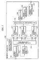
- Fig. 1 shows functional blocks in a transmitter apparatus 100 applying the OFCDM radio communication method according to the prior art.
- the transmitter apparatus 100 applying the OFCDM radio communication method is configured with an information channel signal processing unit 110 , an information symbol generating unit 111, an error correction encoding unit 112, a data modulating unit 113, a serial-parallel converting unit 114, symbol duplicating units 115, a spreading signal generating unit 116 , multiplying units 117, a signal synthesizing unit 118, a frequency-time converting unit (IFFT) 119, a guard interval inserting unit 120, and an OFCDM outgoing signal outputting unit 121.
- an information channel signal processing unit 110 an information symbol generating unit 111
- an error correction encoding unit 112 a data modulating unit 113
- a serial-parallel converting unit 114 serial-parallel converting unit 114
- symbol duplicating units 115 symbol duplicating units 115
- a spreading signal generating unit 116 multiplying units 117, a signal synthesizing unit 118, a frequency-time converting unit (IFFT)
- Step A the symbol duplicating units 115 of the transmitter apparatus 100 duplicate information symbols generated by the information symbol generating unit 111 along the direction of the frequency axis and the direction of the time axis.
- each multiplying unit 117 of the transmitter apparatus 100 multiplies each of the information symbols duplicated along the direction of the frequency axis and the direction of the time axis by one chip of a spreading code generated by the spreading signal generating unit 116.
- Step C the OFCDM outgoing signal outputting unit 121 of the transmitter apparatus 100 performs parallel transmission of the chips after spreading by use of sub-carriers having different frequencies and OFCDM symbols having different timings.
- Fig. 3 shows functional blocks of a receiver apparatus 200 applying the OFCDM radio communication method according to the prior art.
- the receiver apparatus 200 applying the OFCDM radio communication method according to the prior art is configured with an OFCDM incoming signal inputting unit 211, a symbol timing synchronizing unit 212, a guard interval removing unit 213, a time-frequency converting unit (FFT) 214, a spreading signal generating unit 215, multiplying units 216, symbol synthesizing units 217, a serial-parallel converting unit 218, a data demodulating unit 219, an error correction decoding unit 220, an information symbol restoring unit 221, and an outputting unit 223.
- FFT time-frequency converting unit
- the multiplying units 216 of the receiver apparatus 200 multiply an OFCDM incoming signal received through the OFCDM incoming signal inputting unit 211 by spreading codes generated by the spreading signal generating unit 215, i.e. the spreading codes identical to the spreading codes multiplied in the transmitter apparatus 100, along the direction of the frequency axis (or along the direction of the time axis, or along both of the direction of the frequency axis and the direction of the time axis).
- the symbol synthesizing units 217 of the receiver apparatus 200 performs reverse spreading of the OFCDM incoming signal over the respective sub-carriers by synthesizing the signal based on a spreading code cycle.
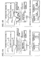
- Figs. 4A and 4B show an aspect of reverse spreading in which the spreading codes are multiplied only along the direction of the frequency axis.
- the spreading codes multiplied on the respective information channels are orthogonal to one another. Accordingly, it is possible to restore the signals on the respective information channels completely after reverse spreading.
- a method for solving the problem i.e. a method for avoiding the continuing flow of unreliable incoming symbols, is known as "interleave", which involves arranging information symbols with a transmitter apparatus in accordance with a predetermined pattern and rearranging of the information symbols with a receiver apparatus in accordance with a reverse pattern to the predetermined pattern.
- An object of the present invention is to provide a radio communication system and a radio communication method which realize radio communication in accordance with the OFCDM radio communication method by use of "interleave" in consideration of the spreading processing, and to provide a transmitter apparatus and a receiver apparatus suitable for use in the system and the method.
- a first aspect of the present invention is summarized as a radio communication system for performing radio communication by combining the OFDM modulation method and the CDMA modulation method.
- the radio communication system comprises a transmitter apparatus configured to estimate conditions of propagation paths used in the radio communication, arrange information symbols along the direction of the frequency axis in accordance with a predetermined pattern based on the estimated conditions of propagation paths, and transmit a radio communication signal including the arranged information symbols; and a receiver apparatus configured to receive the radio communication signal, and rearrange the information symbol included in the radio communication signal along the direction of the frequency axis in accordance with a reverse pattern to the predetermined pattern.
- a second aspect of the present invention is summarized as a radio communication method for performing radio communication by combining the OFDM modulation method and the CDMA modulation method, the method comprising the steps of: (A) estimating conditions of propagation paths used in the radio communication, arranging information symbols along the direction of the frequency axis in accordance with a predetermined pattern based on the estimated conditions of propagation paths, and transmitting a radio communication signal including the arranged information symbols, in a transmitter apparatus; and (B) receiving the radio communication signal, and rearranging the information symbol included in the radio communication signal along the direction of the frequency axis in accordance with a reverse pattern to the predetermined pattern, in a receiver apparatus.
- a third aspect of the present invention is summarized as a transmitter apparatus used in a radio communication system for performing radio communication by combining the OFDM modulation method and the CDMA modulation method.
- the transmitter apparatus estimates conditions of propagation paths used in the radio communication, arranges information symbols along the direction of the frequency axis in accordance with a predetermined pattern based on the estimated conditions of propagation paths, and transmits a radio communication signal including the arranged information symbols.
- the transmitter apparatus may comprise a plurality of symbol arrangers configured to arrange the information symbols along the direction of the frequency axis in accordance with the predetermined pattern; a propagation path condition estimator configured to estimate the conditions of propagation paths; a symbol arrangement scheme selector configured to select the symbol arranger for arranging the information symbols from among the plurality of symbol arrangers, based on the estimated conditions of propagation paths; and a signal transmitter configured to transmit the radio communication signal including the arranged information symbols.
- the plurality of symbol arrangers may comprise a first symbol arrangers configured to arrange the information symbols after error correction encoding along the direction of the frequency axis in accordance with the predetermined pattern; a second symbol arrangers configured to arrange the information symbols after data modulation along the direction of the frequency axis in accordance with the predetermined pattern; and a third symbol arrangers configured to arrange the chips which spread the information symbols along the direction of the frequency axis in accordance with the predetermined pattern.
- the transmitter apparatus may comprise a pattern selector configured to select the predetermined pattern based on the estimated conditions of propagation paths; a symbol arranger configured to arrange the information symbols along the direction of the frequency axis in accordance with the selected predetermined pattern; and a signal transmitter configured to transmit the radio communication signal including the arranged information symbols.
- the symbol arranger may arrange the information symbols after error correction encoding along the direction of the frequency axis in accordance with the predetermined pattern.
- the symbol arranger may arrange the information symbols after data modulation along the direction of the frequency axis in accordance with the predetermined pattern.
- the symbol arranger may arrange chips which spread the information symbols along the direction of the frequency axis in accordance with the predetermined pattern.
- the symbol arrangement may be performed along both the direction of the frequency axis and the direction of the time axis.
- a fourth aspect of the present invention is summarized as a receiver apparatus used in a radio communication system for performing radio communication by combining the OFDM modulation method and the CDMA modulation method
- the receiver apparatus is configured to receive a radio communication signal from a transmitter, and rearrange information symbol included in the radio communication signal along the direction of the frequency axis in accordance with a reverse pattern to a predetermined pattern.
- a transmitter apparatus estimates conditions of propagation paths used in the radio communication, arranges the information symbols along the direction of the frequency axis in accordance with the predetermined pattern based on the estimated conditions of propagation paths, and transmits the radio communication signal including the arranged information symbols.
- the receiver apparatus may comprise a signal receiver configured to receive the radio communication signal; and a plurality of symbol rearranger configured to rearrange the information symbol included in the radio communication signal along the direction of the frequency axis in accordance with the reverse pattern to the predetermined pattern, and the symbol rearranger which is selected from among the plurality of the symbol rearranger may rearrange the information symbols.
- the plurality of symbol rearranger may comprise a first symbol rearranger configured to rearrange the information symbol after data demodulation along the direction of the frequency axis in accordance with the reverse pattern to the predetermined pattern; a second symbol rearranger configured to rearrange the information symbol after reverse spreading along the direction of the frequency axis in accordance with the reverse pattern to the predetermined pattern; and a third symbol rearranger configured to rearrange chips after the time-frequency conversion along the direction of the frequency axis in accordance with the reverse pattern to the predetermined pattern, the chips spreading the information symbols.
- the receiver apparatus may comprise a signal receiver configured to receive the radio communication signal; and a symbol rearranger configured to rearrange the information symbol included in the radio communication signal along the direction of the frequency axis in accordance with the reverse pattern to the predetermined pattern.
- the symbol rearranger may rearrange the information symbol after data demodulation along the direction of the frequency axis in accordance with the reverse pattern to the predetermined pattern.
- the symbol rearranger may rearrange the information symbol after reverse spreading along the direction of the frequency axis in accordance with the reverse pattern to the predetermined pattern.
- the symbol rearranger may rearrange chips after the time-frequency conversion along the direction of the frequency axis in accordance with the reverse pattern to the predetermined pattern.
- the chips spread the information symbols.
- the symbol rearrangement may be performed along both the direction of the frequency axis and the direction of the time axis. In the above aspects, the symbol rearrangement may be performed along at least one of the direction of the frequency axis or the direction of the time axis.
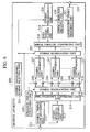
- the radio communication system of this embodiment is configured with a transmitter apparatus 100 and a receiver apparatus 200, and is designed to perform radio communication by combining the OFDM modulation method and the CDMA modulation method.
- the transmitter apparatus 100 of this embodiment is configured with an information symbol generating unit 111, an error correction encoding unit 112, a data modulating unit 113, a serial-parallel converting unit 114, symbol duplicating units 115, a spreading signal generating unit 116 , multiplying units 117 , a signal synthesizing unit 118 , a frequency-time converting unit (IFFT) 119, a guard interval inserting unit 120, an OFCDM outgoing signal outputting unit 121, a control channel incoming signal inputting unit 131, a propagation path condition estimating unit 132, a transmission parameter information inputting unit 133, a symbol arrangement scheme selecting unit 134, and a plurality of symbol arranging units 151 to 153.
- IFFT frequency-time converting unit
- Each of the information channel signal processing units 110 1 to 110 n which is configured to perform signal processing on each of the information channels 1 to N is configured with the information symbol generating unit 111, the error correction encoding unit 112 , the data modulating unit 113, the serial-parallel converting unit 114, the symbol duplicating units 115, the spreading signal generating unit 116, the multiplying units 117, and the plurality of symbol arranging units 151 and 152.
- the information symbol generating unit 111 is configured to generate an information symbol to be transmitted through each information channel.
- the error correction encoding unit 112 is configured to perform predetermined error correction encoding on the information symbol in order to allow the receiver apparatus 200 to perform error correction decoding.
- the error correction encoding unit 112 performs error correction encoding such as turbo encoding.
- the data modulating unit 113 is configured to perform data modulation, such as quadrature phase shift keying (QPSK) modulation, on the error correction encoded information symbol.
- the serial-parallel converting unit 114 is configured to perform serial-parallel conversion of the data modulated information symbol to simultaneously transmit a plurality of information symbols.
- the symbol duplicating unit 115 is configured to duplicate the serial-parallel converted information symbol in the number equal to a spreading cycle of the spreading codes.
- the spreading signal generating unit 116 is configured to generate a spreading code (a spreading signal) corresponding to each information channel.
- the multiplying unit 117 is configured to multiply each of the information signals duplicated by the symbol duplicating unit 115, by the spreading code which is generated by the spreading signal generating unit 116.
- the signal synthesizing unit 118 is configured to multiplex the information symbol corresponding to each information channel.
- the frequency-time converting unit (IFFT) 119 is configured to perform frequency-time conversion (IFFT) on the multiplexed information symbol and thereby to generate an OFCDM outgoing signal.
- the guard interval inserting unit 120 is configured to insert a guard interval to each information symbol, so as to reduce an influence of interference between the symbols attributable to a radio communication signal (the OFCDM outgoing signal) reaching the receiver apparatus 200 late due to an influence by the multiple propagation paths.
- the OFCDM outgoing signal outputting unit 121 constitutes a signal transmitter configured to transmit an OFCDM outgoing signal including the spread parallel symbols by radio communication using carriers having various frequencies.
- the control channel incoming signal inputting unit 131 is configured to receive a control channel which includes propagation path information such as an incoming signal-to-interference and noise ratio (SINR), delay spread or a maximum Doppler frequency.
- SINR incoming signal-to-interference and noise ratio
- the control channel incoming signal inputting unit 131 can receive the above-described control channel from the receiver apparatus 200 in any radio communication method such as the OFCDM communication method, the MC-CDMA communication method, the MC/DS-CDMA communication method, the OFDM communication method, the DS-CDMA communication n method, the TDMA communication method or the FDMA communication method.
- any radio communication method such as the OFCDM communication method, the MC-CDMA communication method, the MC/DS-CDMA communication method, the OFDM communication method, the DS-CDMA communication n method, the TDMA communication method or the FDMA communication method.
- the propagation path condition estimating unit 132 is configured to estimate conditions of propagation paths used in the radio communication between the transmitter apparatus 100 and the receiver apparatus 200, based on the propagation path information in the control channel received by the control channel incoming signal inputting unit 131.
- the transmission parameter information inputting unit 133 is configured to receive transmission parameter information such as a spreading direction (the direction of the frequency axis or the direction of the time axis), the spreading cycle, the data modulation method, the number of multiplexed codes or an error correction encoding rate.
- transmission parameter information such as a spreading direction (the direction of the frequency axis or the direction of the time axis), the spreading cycle, the data modulation method, the number of multiplexed codes or an error correction encoding rate.
- the symbol arrangement scheme selecting unit 134 is configured to select the symbol arranging unit for arranging the information symbols from among the plurality of symbol arranging units 151 to 153, based on the propagation path conditions estimated by the propagation path condition estimating unit 132 and the transmission parameter information inputted through the transmission parameter information inputting unit 133.
- the symbol arrangement scheme selecting unit 134 can select the symbol arrangement scheme by selecting the symbol arranging unit for arranging the information symbols from among the plurality of symbol arranging units 151 to 153, based on the propagation path conditions and the transmission parameter information.
- the symbol arranging units 151 to 153 are configured to arrange the information symbols along the direction of the frequency axis or the direction of the time axis in accordance with a predetermined pattern in response to a result of selection by the symbol arrangement scheme selecting unit 134.
- the symbol arranging units 151 to 153 arrange the information symbols along the direction of the frequency axis or the direction of the time axis such that reception of the unreliable information symbols does not continue in the receiver apparatus 200.
- the symbol arranging unit 151 constitutes a first symbol arranger configured to arrange the information symbols after error correction encoding by the error correction encoding unit 112 along the direction of the frequency axis or the direction of the time axis in accordance with a predetermined pattern.
- the symbol arranging unit 152 constitutes a second symbol arranger configured to arrange the information symbols after the modulation by the data modulating unit 113 and after the serial-parallel conversion by the serial-parallel converting unit 114 along the direction of the frequency axis or the direction of the time axis in accordance with a predetermined pattern.
- the symbol arranging unit 153 constitutes a third symbol arranger configured to arrange the chips, which spread the information symbols by the multiplying units 117, along the direction of the frequency axis or the direction of the time axis in accordance with a predetermined pattern.
- the receiver apparatus 200 of this embodiment is configured with an OFCDM incoming signal inputting unit 211, a symbol timing synchronizing unit 212, a guard interval removing unit 213, a time-frequency converting unit (FFT) 214, a spreading signal generating unit 215, multiplying units 216, symbol synthesizing units 217, a serial-parallel converting unit 218, a data demodulating unit 219, an error correction decoding unit 220, an information symbol restoring unit 221, an outputting unit 223, a symbol arrangement scheme selecting unit 231, and a plurality of symbol rearranging units 251 to 253.
- FFT time-frequency converting unit
- the OFCDM incoming signal inputting unit 211 constitutes a signal receiver configured to receive an OFCDM incoming signal ( a radio communication signal) transmitted from the transmitter apparatus 100.
- the symbol timing synchronizing unit 212 is configured to establish a symbol timing cycle concerning the received OFCDM incoming signal.
- the guard interval removing unit 213 is configured to remove the guard interval included in the received OFCDM incoming signal.
- the time-frequency converting unit (FFT) 214 is configured to separate the OFCDM incoming signal after the guard interval is removed into components of the respective sub-carrier frequencies by performing time-frequency conversion (FFT).
- the spreading signal generating unit 215 is configured to generate a spreading signal (a spreading code) corresponding to each information channel as similar to the spreading signal generating unit 116 of the transmitter apparatus 100.
- the multiplying unit 216 is configured to multiply each of the information signals separated into the components of the respective sub-carrier frequencies by the time-frequency converting unit (FFT) 214, by the spreading code which is generated by the spreading signal generating unit 215.
- FFT time-frequency converting unit
- the symbol synthesizing unit 217 is configured to restore (reverse spread) the information symbol before spreading by synthesizing the information symbol being multiplied by the spreading codes by the multiplying units 216 along the spreading cycle.
- the serial-parallel converting unit 218 is configured to perform serial-parallel conversion of the restored information symbol.
- the data demodulating unit 219 is configured to perform data demodulation on the serial-parallel converted information symbol.
- the error correction decoding unit 220 is configured to perform error correction decoding on the information symbol after the data demodulation.
- the information symbol restoring unit 221 is configured to restore the information symbol after error correction decoding to the information symbol which is originally generated by the information symbol generating unit 111 of the transmitter apparatus 100.
- the outputting unit 223 is configured to output the information symbol restored by the information symbol restoring unit 221.
- the symbol arrangement scheme selecting unit 231 is configured to select the symbol rearranging unit for rearranging the information symbol from among the plurality of symbol rearranging units 251 to 253.
- the symbol arrangement scheme selecting unit 231 may select the symbol rearranging unit for rearranging the information symbol from among the plurality of symbol rearranging units 251 to 253 based on an instruction from the transmitter apparatus 100.
- the symbol arrangement scheme selecting unit 231 may select the symbol rearranging unit for rearranging the information symbol from among the plurality of symbol rearranging units 251 to 253 based on the estimated propagation path conditions or the known transmission parameter information.
- the plurality of symbol rearranging units 251 to 253 are configured to rearrange the information symbol included in the OFCDM incoming signal (the radio communication signal) along the direction of the frequency axis or the direction of the time axis in accordance with a reverse pattern to the predetermined pattern in response to an instruction from the symbol arrangement scheme selecting unit 231.
- the symbol rearranging unit 251 constitutes a first symbol rearranger configured to rearrange the information symbol after the data demodulation by the data demodulating unit 219 along the direction of the frequency axis or the direction of the time axis in accordance with a reverse pattern to the predetermined pattern.
- the symbol rearranging unit 252 constitutes a second symbol rearranger configured to rearrange the information symbol after reverse spreading by the multiplying unit 216 and after the synthesis by the symbol synthesizing unit 217 along the direction of the frequency axis or the direction of the time axis in accordance with a reverse pattern to the predetermined pattern.
- the symbol rearranging unit 253 constitutes a third symbol rearranger configured to rearrange the chips after the time-frequency conversion (FFT) by the time-frequency converting unit 214 along the direction of the frequency axis or the direction of the time axis in accordance with a reverse pattern to the predetermined pattern.
- FFT time-frequency conversion
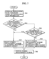
- Fig. 7 shows the operation of the transmitter apparatus 100 of the radio communication system of this embodiment.
- the propagation path condition estimating unit 132 of the transmitter apparatus 100 estimates the propagation path conditions between the transmitter apparatus 100 and the receiver apparatus 200 based on the propagation path information such as the incoming SINR, the delay spread or the maximum Doppler frequency.
- Step 302 the symbol arrangement scheme selecting unit 134 of the transmitter apparatus 100 checks whether the estimated propagation path conditions largely affect the loss of orthogonalities among the spreading codes or not.
- the symbol arrangement scheme selecting unit 134 checks whether the transmission parameter information (such as the spreading direction, the spreading cycle, the modulation method, the number of the multiplexed codes or the error correction encoding rate) obtained through the transmission parameter information inputting unit 133 is resistant to the loss of the orthogonalities among the spreading codes or not.
- the transmission parameter information such as the spreading direction, the spreading cycle, the modulation method, the number of the multiplexed codes or the error correction encoding rate
- the symbol arrangement scheme selecting unit 134 selects the symbol arranging unit for arranging the information symbols from among the plurality of symbol arranging units 151 to 153, so as to reduce the loss of the orthogonalities among the spreading codes caused by symbol arrangement.
- the symbol arrangement scheme selecting unit 134 switches the arrangement scheme so as to perform symbol arrangement on bits after error correction encoding. In other words, the symbol arrangement scheme selecting unit 134 selects the symbol arranging unit 151 for performing the symbol arrangement.
- reception of unreliable information symbols will not continue at the receiver apparatus 200 while avoiding an increase in the interference among the information channels . Accordingly, it is possible to improve a transmission characteristic as compared to other schemes.
- the symbol arrangement scheme selecting unit 134 selects the symbol arranging unit for arranging the information symbols from among the plurality of symbol arranging units 151 to 153, so as to maximize a frequency diversity effect.
- the symbol arrangement scheme selecting unit 134 switches the arrangement scheme so as to perform the symbol arrangement on bits after spreading. In other words, the symbol arrangement scheme selecting unit 134 selects the symbol arranging unit 153 for performing the symbol arrangement.
- Step 306 the symbol arranging unit selected by the symbol arrangement scheme selecting unit 134 in Step 304 or Step 305 performs the arrangement of the information symbols.
- the symbol arranging units 151 to 153 of the transmitter apparatus 100 arrange the information symbols along the direction of the frequency axis or the direction of the time axis in accordance with the predetermined pattern based on the propagation path conditions estimated by the propagation path condition estimating unit 132, and the symbol rearranging units 251 to 253 of the receiver apparatus 200 rearrange the information symbols included in the radio communication signal along the direction of the frequency axis or the direction of the time axis in accordance with a reverse pattern to the predetermined pattern based on the propagation path conditions. Therefore, it is possible to avoid a problem such as the continued reception of unreliable information symbols at the receiver apparatus 200.
- a radio communication system according to a second embodiment of the present invention will be described with reference to Fig. 8 to Fig. 10.
- the radio communication system of this embodiment will be described below mainly regarding differences from the radio communication system according to the first embodiment.
- the transmitter apparatus 100 of this embodiment includes a symbol arrangement pattern selecting unit 135 instead of the transmission parameter information inputting unit 133 and the symbol arrangement scheme selecting unit 134 which are provided to the transmitter apparatus 100 according to the first embodiment.
- the transmitter apparatus 100 of this embodiment includes only the symbol arranging unit 151 instead of the plurality of symbol arranging units 151 to 153 which are provided to the transmitter apparatus 100 according to the first embodiment.
- the symbol arrangement pattern selecting unit 135 constitutes a pattern selector configured to estimate reliability of the consecutive information symbols based on the propagation path conditions estimated by the propagation path condition estimating unit 132 and thereby to select an arrangement pattern (a predetermined pattern) so as to prevent the continued reception of unreliable information symbols at the receiver apparatus 200.
- the symbol arrangement pattern selecting unit 135 notifies the symbol arranging unit 151 of the selected predetermined pattern.
- the symbol arranging unit 151 is provided for arranging (mapping) the consecutive information symbols after error correction encoding along the direction of the frequency axis or the direction of the time axis in accordance with the predetermined pattern notified by the symbol arrangement pattern selecting unit 135.
- the bits of the consecutive information symbols after error correction encoding are mapped into different data modulation symbols, and the information symbols after the data modulation are spread into the sub-carriers, which are consecutive over the spreading cycle, and then transmitted.
- the receiver apparatus 200 of this embodiment includes a symbol arrangement pattern selecting unit 232 instead of the symbol arrangement scheme selecting unit 231 provided to the receiver apparatus 200 according to the first embodiment.
- the receiver apparatus 200 of this embodiment includes only the symbol rearranging unit 251 instead of the plurality of symbol rearranging units 251 to 253 which are provided to the receiver apparatus 200 according to the first embodiment.
- the symbol arrangement pattern selecting unit 232 is configured to instruct a reverse pattern to the predetermined pattern to the symbol rearranging unit 251 for use in rearrangement of the information symbols by the symbol rearranging unit 251.
- the symbol arrangement pattern selecting unit 232 may instruct the reverse pattern to the predetermined pattern to the symbol rearranging unit 251 for use in rearrangement of the information symbols by the symbol rearranging unit 251 based on an instruction from the transmitter apparatus 100.
- the symbol arrangement pattern selecting unit 232 may instruct the reverse pattern to the predetermined pattern to the symbol rearranging unit 251 for use in rearrangement of the information symbols by the symbol rearranging unit 251 based on the estimated propagation path conditions.
- the symbol rearranging unit 251 is configured to rearrange the information symbols after the data demodulation along the direction of the frequency axis or the direction of the time axis in accordance with the reverse pattern to the predetermined pattern.
- Fig. 10 shows the operation of the transmitter apparatus 100 of the radio communication system of this embodiment.
- the propagation path condition estimating unit 132 of the transmitter apparatus 100 estimates the propagation path conditions between the transmitter apparatus 100 and the receiver apparatus 200 based on the propagation path information such as the incoming SINR, the delay spread or the maximum Doppler frequency.
- Step 402 the symbol arrangement pattern selecting unit 135 of the transmitter apparatus 100 estimates the reliability of the consecutive information symbols after error correction encoding.
- the symbol arrangement pattern selecting unit 135 selects the arrangement pattern (the predetermined pattern) so as to prevent the continued reception of unreliable information symbols at the receiver apparatus 200.
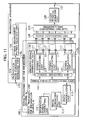
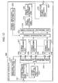
- a radio communication system according to a third embodiment of the present invention will be described with reference to Fig. 11 and Fig. 12.
- the radio communication system of this embodiment will be described below mainly regarding differences from the radio communication systems according to the first and second embodiments.
- the transmitter apparatus 100 of this embodiment includes only the symbol arranging unit 152 instead of the plurality of symbol arranging units 151 to 153 which are provided to the transmitter apparatus 100 according to the first embodiment.
- the symbol arranging unit 152 is provided for arranging (mapping) the consecutive information symbols after the data modulation along the direction of the frequency axis or the direction of the time axis in accordance with the predetermined pattern notified by the symbol arrangement pattern selecting unit 135.
- the receiver apparatus 200 of this embodiment includes only the symbol rearranging unit 252 instead of the plurality of symbol rearranging units 251 to 253 which are provided to the receiver apparatus 200 according to the first embodiment.
- the symbol rearranging unit 252 is configured to rearrange the information symbols after spreading along the direction of the frequency axis or the direction of the time axis in accordance with the reverse pattern to the predetermined pattern.
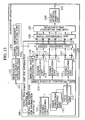
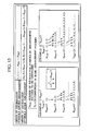
- a radio communication system according to a fourth embodiment of the present invention will be described with reference to Fig. 13 and Fig . 14.
- the radio communication system of this embodiment will be described below mainly regarding differences from the radio communication systems according to the first to third embodiments.
- the transmitter apparatus 100 of this embodiment includes only the symbol arranging unit 153 instead of the plurality of symbol arranging units 151 to 153 which are provided to the transmitter apparatus 100 according to the first embodiment.
- the symbol arranging unit 153 is provided for arranging (mapping) the chips, which spread the information symbols, along the direction of the frequency axis or the direction of the time axis in accordance with the predetermined pattern notified by the symbol arrangement pattern selecting unit 135.
- the plurality of consecutive chips after spreading are transmitted by sub-carriers which are not consecutive over the spreading cycle.
- the symbol arranging unit 153 may perform the arrangement in a lump after the synthesis by the signal synthesizing unit 118.
- the receiver apparatus 200 of this embodiment includes only the symbol rearranging unit 253 instead of the plurality of symbol rearranging units 251 to 253 which are provided to the receiver apparatus 200 according to the first embodiment.
- the symbol rearranging unit 253 is configured to rearrange the chips after the time-frequency conversion along the direction of the frequency axis or the direction of the time axis in accordance with the reverse pattern to the predetermined pattern.
- the radio communication system so as to include the symbol arranging units 151 to 153, and the symbol rearranging units 251 to 253, and to select one of the symbol arranging units and one of the symbol rearranging units to perform the above-described processing.
- the above-described method can be expressed by a general formula as (X 1 , X 1 +N size /2, X 2 , X 2 +N size /2, ..., X Nsize /2, X Nsize /2+N size /2), which is the order of the information symbols after arrangement.
- reference code N size denotes the number of the information symbols in the arrangement pattern to be generated.
- reference code X i demotes an i-th component of the basic arrangement pattern.
- the present invention it is possible to configure the OFCDM radio communication system so as to prevent the continued reception of the unreliable information symbols at the receiver apparatus 200 . In this way, it is possible to improve the transmission quality.
Landscapes
- Engineering & Computer Science (AREA)
- Signal Processing (AREA)
- Computer Networks & Wireless Communication (AREA)
- Quality & Reliability (AREA)
- Mobile Radio Communication Systems (AREA)
- Radio Transmission System (AREA)
- Transmitters (AREA)
Applications Claiming Priority (2)
| Application Number | Priority Date | Filing Date | Title |
|---|---|---|---|
| JP2002296549 | 2002-10-09 | ||
| JP2002296549A JP4041719B2 (ja) | 2002-10-09 | 2002-10-09 | 無線通信システム、無線通信方法、これらに用いて好適な送信装置及び受信装置 |
Publications (2)
| Publication Number | Publication Date |
|---|---|
| EP1408642A2 true EP1408642A2 (de) | 2004-04-14 |
| EP1408642A3 EP1408642A3 (de) | 2006-11-29 |
Family
ID=32025547
Family Applications (1)
| Application Number | Title | Priority Date | Filing Date |
|---|---|---|---|
| EP20030022836 Withdrawn EP1408642A3 (de) | 2002-10-09 | 2003-10-08 | Adaptive Zuweisung für Mehrträgerspreizspektrumübertragung |
Country Status (4)
| Country | Link |
|---|---|
| US (1) | US7606196B2 (de) |
| EP (1) | EP1408642A3 (de) |
| JP (1) | JP4041719B2 (de) |
| CN (1) | CN100514893C (de) |
Cited By (1)
| Publication number | Priority date | Publication date | Assignee | Title |
|---|---|---|---|---|
| US7453856B2 (en) | 2004-09-03 | 2008-11-18 | Telefonaktiebolaget Lm Ericsson (Publ) | Method, apparatus, and communications interface for sending and receiving data blocks associated with different multiple access techniques |
Families Citing this family (15)
| Publication number | Priority date | Publication date | Assignee | Title |
|---|---|---|---|---|
| JP4171261B2 (ja) | 2001-08-27 | 2008-10-22 | 松下電器産業株式会社 | 無線通信装置及び無線通信方法 |
| KR100584439B1 (ko) * | 2003-11-05 | 2006-05-26 | 삼성전자주식회사 | 다중 안테나를 사용하는 직교주파수분할다중 시스템에서간섭신호 제거 장치 및 방법 |
| RU2369009C2 (ru) | 2004-06-24 | 2009-09-27 | Панасоник Корпорэйшн | Устройство беспроводной передачи, устройство беспроводного приема и способ упорядочения символов |
| WO2006013705A1 (ja) * | 2004-08-06 | 2006-02-09 | Matsushita Electric Industrial Co., Ltd. | マルチキャリア通信における無線送信装置および無線送信方法 |
| JP4539969B2 (ja) * | 2004-08-25 | 2010-09-08 | モトローラ・インコーポレイテッド | マルチキャリアスペクトル拡散通信装置及びマルチキャリアスペクトル拡散通信方法 |
| KR101084124B1 (ko) * | 2004-10-25 | 2011-11-17 | 엘지전자 주식회사 | 직교 주파수 분할 다중화를 이용한 브로드캐스트에적용되는 차등 진폭 위상 변조 방법 |
| JP4611182B2 (ja) * | 2005-02-16 | 2011-01-12 | パナソニック株式会社 | 無線端末装置及び通信方式切り換え方法 |
| CN101138262B (zh) | 2005-03-09 | 2012-11-14 | 富士通株式会社 | 通信系统、发送方法 |
| EP1876741A4 (de) | 2005-04-18 | 2013-06-12 | Sharp Kk | Vorrichtung und verfahren zur drahtlosen kommunikation |
| JP4664980B2 (ja) | 2005-08-25 | 2011-04-06 | 富士通株式会社 | 移動端末及び基地局装置 |
| FR2894416B1 (fr) * | 2005-12-05 | 2008-02-29 | Commissariat Energie Atomique | Procede et dispositif de selection des parametres d'etalement d'un systeme ofdm cdma |
| US20070149132A1 (en) | 2005-12-22 | 2007-06-28 | Junyl Li | Methods and apparatus related to selecting control channel reporting formats |
| US9338767B2 (en) | 2005-12-22 | 2016-05-10 | Qualcomm Incorporated | Methods and apparatus of implementing and/or using a dedicated control channel |
| JP2008035285A (ja) | 2006-07-28 | 2008-02-14 | Kyocera Corp | 無線通信装置及び無線通信方法 |
| WO2016031496A1 (ja) * | 2014-08-27 | 2016-03-03 | 三菱電機株式会社 | 送信装置、送信方法、受信装置、および受信方法 |
Citations (3)
| Publication number | Priority date | Publication date | Assignee | Title |
|---|---|---|---|---|
| EP1124344A1 (de) | 1999-08-20 | 2001-08-16 | Matsushita Electric Industrial Co., Ltd. | Ofdm nachrichten übertragungsvorrichtung |
| JP2002190788A (ja) | 2000-03-17 | 2002-07-05 | Matsushita Electric Ind Co Ltd | 無線通信装置および無線通信方法 |
| JP2002296549A (ja) | 2001-03-30 | 2002-10-09 | Topcon Corp | レンズメータ |
Family Cites Families (9)
| Publication number | Priority date | Publication date | Assignee | Title |
|---|---|---|---|---|
| DE19647833B4 (de) * | 1996-11-19 | 2005-07-07 | Deutsches Zentrum für Luft- und Raumfahrt e.V. | Verfahren zur gleichzeitigen Funkübertragung digitaler Daten zwischen mehreren Teilnehmerstationen und einer Basisstation |
| JP3236273B2 (ja) | 1999-05-17 | 2001-12-10 | 三菱電機株式会社 | マルチキャリア伝送システムおよびマルチキャリア変調方法 |
| US6816555B2 (en) * | 2000-02-18 | 2004-11-09 | Sony Corporation | Signal component demultiplexing apparatus, filter apparatus, receiving apparatus, communication apparatus, and communication method |
| CN1364358A (zh) | 2000-03-17 | 2002-08-14 | 松下电器产业株式会社 | 无线通信装置和无线通信方法 |
| US7440509B2 (en) * | 2001-06-21 | 2008-10-21 | Motorola, Inc. | Method and system for interference averaging in a wireless communication system |
| EP1496633A4 (de) * | 2002-04-12 | 2010-10-20 | Panasonic Corp | Mehrträgerkommunikationseinrichtung und mehrträgerkommunikationsverfahren |
| US7436757B1 (en) * | 2002-06-21 | 2008-10-14 | Nortel Networks Limited | Scattered pilot and filtering for channel estimation |
| US7289459B2 (en) * | 2002-08-07 | 2007-10-30 | Motorola Inc. | Radio communication system with adaptive interleaver |
| DE602004020860D1 (de) * | 2003-12-25 | 2009-06-10 | Ntt Docomo Inc | Funkkommunikationssystem, Sender, Empfänger und Funkkommunikationsverfahren |
-
2002
- 2002-10-09 JP JP2002296549A patent/JP4041719B2/ja not_active Expired - Fee Related
-
2003
- 2003-10-07 US US10/679,488 patent/US7606196B2/en not_active Expired - Fee Related
- 2003-10-08 EP EP20030022836 patent/EP1408642A3/de not_active Withdrawn
- 2003-10-09 CN CNB2003101003206A patent/CN100514893C/zh not_active Expired - Fee Related
Patent Citations (3)
| Publication number | Priority date | Publication date | Assignee | Title |
|---|---|---|---|---|
| EP1124344A1 (de) | 1999-08-20 | 2001-08-16 | Matsushita Electric Industrial Co., Ltd. | Ofdm nachrichten übertragungsvorrichtung |
| JP2002190788A (ja) | 2000-03-17 | 2002-07-05 | Matsushita Electric Ind Co Ltd | 無線通信装置および無線通信方法 |
| JP2002296549A (ja) | 2001-03-30 | 2002-10-09 | Topcon Corp | レンズメータ |
Cited By (1)
| Publication number | Priority date | Publication date | Assignee | Title |
|---|---|---|---|---|
| US7453856B2 (en) | 2004-09-03 | 2008-11-18 | Telefonaktiebolaget Lm Ericsson (Publ) | Method, apparatus, and communications interface for sending and receiving data blocks associated with different multiple access techniques |
Also Published As
| Publication number | Publication date |
|---|---|
| CN1497885A (zh) | 2004-05-19 |
| JP2004134978A (ja) | 2004-04-30 |
| EP1408642A3 (de) | 2006-11-29 |
| US20040071105A1 (en) | 2004-04-15 |
| CN100514893C (zh) | 2009-07-15 |
| JP4041719B2 (ja) | 2008-01-30 |
| US7606196B2 (en) | 2009-10-20 |
Similar Documents
| Publication | Publication Date | Title |
|---|---|---|
| JP5062852B2 (ja) | パイロット信号伝送の方法 | |
| KR100401801B1 (ko) | 데이터 전송 성능을 개선하기 위한 직교주파수 분할 다중통신 시스템 및 방법 | |
| JP4964239B2 (ja) | パイロット信号を送信するための方法および装置 | |
| US7848438B2 (en) | Method and apparatus for pilot signal transmission | |
| EP1489775B1 (de) | Verfahren und vorrichtung zur übertragung für eine mobile kommunikationsanordnung, basierend auf ofdm | |
| US7606196B2 (en) | Radio communication system, radio communication method, and transmitter apparatus and receiver apparatus suitable for use in the same | |
| EP1585246A2 (de) | Einrichtung und Verfahren zum Umschalten zwischen einem Adaptivmodulationsmodus und einem Diversitätsmodus in einem breitbandigen drahtlosen Vermittlungssystem | |
| CN101056133B (zh) | 正交频分复用系统的多天线发射分集方法及其装置 | |
| US7616608B2 (en) | OFDM-CDMA transmission device and OFDM-CDMA transmission method | |
| EP1901459B1 (de) | Vorrichtung und Verfahren zur drahtlosen Kommunikation | |
| WO2006069401A1 (en) | Constrained hopping in wireless communication systems | |
| WO2004034620A1 (ja) | マルチキャリア送信装置及びマルチキャリア送信方法 | |
| JP2004336746A (ja) | 多重アンテナを用いる直交周波分割多重システムにおけるチャネルの推定装置及び方法 | |
| KR100584439B1 (ko) | 다중 안테나를 사용하는 직교주파수분할다중 시스템에서간섭신호 제거 장치 및 방법 | |
| KR100981552B1 (ko) | 주파수분할 다중접속 시스템에서 상향링크 파일롯의 송수신장치 및 방법 | |
| KR101137345B1 (ko) | 이동 통신 시스템에서 분산된 파일럿 신호가 포함된 신호를송수신하는 방법 | |
| US20090270052A1 (en) | Apparatus and method for radio transmission | |
| KR100641066B1 (ko) | 무선 통신 시스템 및 이를 동작시키는 방법 | |
| KR100683499B1 (ko) | 블록 단위의 부분 캐리어 확산을 이용한 멀티캐리어cdma 전송 장치 및 그 방법 | |
| US7817744B2 (en) | Wireless communication apparatus and data multiplexing method | |
| JP4539969B2 (ja) | マルチキャリアスペクトル拡散通信装置及びマルチキャリアスペクトル拡散通信方法 | |
| KR101100208B1 (ko) | 다수의 반송파를 이용하여 데이터를 전송하는 장치 및 방법 | |
| JP2005057610A (ja) | マルチキャリア通信装置およびマルチキャリア通信方法 |
Legal Events
| Date | Code | Title | Description |
|---|---|---|---|
| PUAI | Public reference made under article 153(3) epc to a published international application that has entered the european phase |
Free format text: ORIGINAL CODE: 0009012 |
|
| 17P | Request for examination filed |
Effective date: 20031008 |
|
| AK | Designated contracting states |
Kind code of ref document: A2 Designated state(s): AT BE BG CH CY CZ DE DK EE ES FI FR GB GR HU IE IT LI LU MC NL PT RO SE SI SK TR |
|
| AX | Request for extension of the european patent |
Extension state: AL LT LV MK |
|
| PUAL | Search report despatched |
Free format text: ORIGINAL CODE: 0009013 |
|
| RIC1 | Information provided on ipc code assigned before grant |
Ipc: H04L 27/26 20060101ALI20061006BHEP Ipc: H04L 5/02 20060101AFI20040203BHEP Ipc: H04L 1/00 20060101ALI20061006BHEP |
|
| AK | Designated contracting states |
Kind code of ref document: A3 Designated state(s): AT BE BG CH CY CZ DE DK EE ES FI FR GB GR HU IE IT LI LU MC NL PT RO SE SI SK TR |
|
| AX | Request for extension of the european patent |
Extension state: AL LT LV MK |
|
| AKX | Designation fees paid |
Designated state(s): DE GB |
|
| 17Q | First examination report despatched |
Effective date: 20090126 |
|
| STAA | Information on the status of an ep patent application or granted ep patent |
Free format text: STATUS: THE APPLICATION IS DEEMED TO BE WITHDRAWN |
|
| 18D | Application deemed to be withdrawn |
Effective date: 20170728 |
|
| RIC1 | Information provided on ipc code assigned before grant |
Ipc: H04L 1/00 20060101ALI20061006BHEP Ipc: H04L 27/26 20060101ALI20061006BHEP Ipc: H04L 5/02 20060101AFI20040203BHEP |