EP1408355B1 - Polarization compensated optical tap - Google Patents
Polarization compensated optical tap Download PDFInfo
- Publication number
- EP1408355B1 EP1408355B1 EP03254965A EP03254965A EP1408355B1 EP 1408355 B1 EP1408355 B1 EP 1408355B1 EP 03254965 A EP03254965 A EP 03254965A EP 03254965 A EP03254965 A EP 03254965A EP 1408355 B1 EP1408355 B1 EP 1408355B1
- Authority
- EP
- European Patent Office
- Prior art keywords
- reflective surface
- polarization
- incidence
- optical
- metallic element
- Prior art date
- Legal status (The legal status is an assumption and is not a legal conclusion. Google has not performed a legal analysis and makes no representation as to the accuracy of the status listed.)
- Expired - Lifetime
Links
- 230000010287 polarization Effects 0.000 title claims abstract description 53
- 230000003287 optical effect Effects 0.000 title claims abstract description 36
- 229910052751 metal Inorganic materials 0.000 claims abstract description 50
- 239000002184 metal Substances 0.000 claims abstract description 41
- 230000003595 spectral effect Effects 0.000 claims description 16
- 239000000758 substrate Substances 0.000 claims description 13
- 230000007704 transition Effects 0.000 claims description 12
- 238000000034 method Methods 0.000 claims description 7
- 239000011521 glass Substances 0.000 claims description 5
- 239000013307 optical fiber Substances 0.000 claims description 4
- 150000003623 transition metal compounds Chemical class 0.000 claims description 2
- 239000003989 dielectric material Substances 0.000 claims 3
- 239000000956 alloy Substances 0.000 claims 1
- 229910045601 alloy Inorganic materials 0.000 claims 1
- 238000005070 sampling Methods 0.000 claims 1
- 239000010408 film Substances 0.000 description 45
- PXHVJJICTQNCMI-UHFFFAOYSA-N Nickel Chemical compound [Ni] PXHVJJICTQNCMI-UHFFFAOYSA-N 0.000 description 27
- WFKWXMTUELFFGS-UHFFFAOYSA-N tungsten Chemical compound [W] WFKWXMTUELFFGS-UHFFFAOYSA-N 0.000 description 25
- 229910052721 tungsten Inorganic materials 0.000 description 25
- 239000010937 tungsten Substances 0.000 description 25
- 229910052759 nickel Inorganic materials 0.000 description 14
- PCHJSUWPFVWCPO-UHFFFAOYSA-N gold Chemical compound [Au] PCHJSUWPFVWCPO-UHFFFAOYSA-N 0.000 description 10
- 229910052737 gold Inorganic materials 0.000 description 10
- 239000010931 gold Substances 0.000 description 10
- 229910052782 aluminium Inorganic materials 0.000 description 9
- XAGFODPZIPBFFR-UHFFFAOYSA-N aluminium Chemical compound [Al] XAGFODPZIPBFFR-UHFFFAOYSA-N 0.000 description 9
- 239000000835 fiber Substances 0.000 description 9
- 150000002739 metals Chemical class 0.000 description 6
- 230000005855 radiation Effects 0.000 description 5
- 229910052723 transition metal Inorganic materials 0.000 description 5
- 150000003624 transition metals Chemical class 0.000 description 5
- 230000005684 electric field Effects 0.000 description 4
- 230000001419 dependent effect Effects 0.000 description 3
- 239000010409 thin film Substances 0.000 description 3
- 229910052581 Si3N4 Inorganic materials 0.000 description 2
- VYPSYNLAJGMNEJ-UHFFFAOYSA-N Silicium dioxide Chemical compound O=[Si]=O VYPSYNLAJGMNEJ-UHFFFAOYSA-N 0.000 description 2
- 238000000576 coating method Methods 0.000 description 2
- 239000011104 metalized film Substances 0.000 description 2
- HQVNEWCFYHHQES-UHFFFAOYSA-N silicon nitride Chemical compound N12[Si]34N5[Si]62N3[Si]51N64 HQVNEWCFYHHQES-UHFFFAOYSA-N 0.000 description 2
- 229910052720 vanadium Inorganic materials 0.000 description 2
- 230000000007 visual effect Effects 0.000 description 2
- RYGMFSIKBFXOCR-UHFFFAOYSA-N Copper Chemical compound [Cu] RYGMFSIKBFXOCR-UHFFFAOYSA-N 0.000 description 1
- BQCADISMDOOEFD-UHFFFAOYSA-N Silver Chemical compound [Ag] BQCADISMDOOEFD-UHFFFAOYSA-N 0.000 description 1
- ATJFFYVFTNAWJD-UHFFFAOYSA-N Tin Chemical compound [Sn] ATJFFYVFTNAWJD-UHFFFAOYSA-N 0.000 description 1
- 238000013459 approach Methods 0.000 description 1
- 230000005540 biological transmission Effects 0.000 description 1
- 238000006243 chemical reaction Methods 0.000 description 1
- 238000005229 chemical vapour deposition Methods 0.000 description 1
- 239000011248 coating agent Substances 0.000 description 1
- 229910052802 copper Inorganic materials 0.000 description 1
- 239000010949 copper Substances 0.000 description 1
- 238000000151 deposition Methods 0.000 description 1
- 230000008021 deposition Effects 0.000 description 1
- 238000009826 distribution Methods 0.000 description 1
- 230000009977 dual effect Effects 0.000 description 1
- 230000008020 evaporation Effects 0.000 description 1
- 238000001704 evaporation Methods 0.000 description 1
- 239000003574 free electron Substances 0.000 description 1
- 238000003780 insertion Methods 0.000 description 1
- 230000037431 insertion Effects 0.000 description 1
- 238000004519 manufacturing process Methods 0.000 description 1
- 229910001092 metal group alloy Inorganic materials 0.000 description 1
- 229910052750 molybdenum Inorganic materials 0.000 description 1
- 238000012544 monitoring process Methods 0.000 description 1
- 229910000510 noble metal Inorganic materials 0.000 description 1
- 229910052710 silicon Inorganic materials 0.000 description 1
- 239000010703 silicon Substances 0.000 description 1
- 235000012239 silicon dioxide Nutrition 0.000 description 1
- 239000000377 silicon dioxide Substances 0.000 description 1
- 229910052709 silver Inorganic materials 0.000 description 1
- 239000004332 silver Substances 0.000 description 1
- 239000007787 solid Substances 0.000 description 1
- 238000004544 sputter deposition Methods 0.000 description 1
- 238000010561 standard procedure Methods 0.000 description 1
- 230000002123 temporal effect Effects 0.000 description 1
- GPPXJZIENCGNKB-UHFFFAOYSA-N vanadium Chemical compound [V]#[V] GPPXJZIENCGNKB-UHFFFAOYSA-N 0.000 description 1
- 229910052727 yttrium Inorganic materials 0.000 description 1
Images


Classifications
-
- G—PHYSICS
- G02—OPTICS
- G02B—OPTICAL ELEMENTS, SYSTEMS OR APPARATUS
- G02B5/00—Optical elements other than lenses
- G02B5/30—Polarising elements
-
- G—PHYSICS
- G02—OPTICS
- G02B—OPTICAL ELEMENTS, SYSTEMS OR APPARATUS
- G02B6/00—Light guides; Structural details of arrangements comprising light guides and other optical elements, e.g. couplings
- G02B6/24—Coupling light guides
- G02B6/26—Optical coupling means
- G02B6/27—Optical coupling means with polarisation selective and adjusting means
- G02B6/2706—Optical coupling means with polarisation selective and adjusting means as bulk elements, i.e. free space arrangements external to a light guide, e.g. polarising beam splitters
- G02B6/2713—Optical coupling means with polarisation selective and adjusting means as bulk elements, i.e. free space arrangements external to a light guide, e.g. polarising beam splitters cascade of polarisation selective or adjusting operations
-
- G—PHYSICS
- G02—OPTICS
- G02B—OPTICAL ELEMENTS, SYSTEMS OR APPARATUS
- G02B5/00—Optical elements other than lenses
- G02B5/30—Polarising elements
- G02B5/3025—Polarisers, i.e. arrangements capable of producing a definite output polarisation state from an unpolarised input state
- G02B5/3066—Polarisers, i.e. arrangements capable of producing a definite output polarisation state from an unpolarised input state involving the reflection of light at a particular angle of incidence, e.g. Brewster's angle
-
- G—PHYSICS
- G02—OPTICS
- G02B—OPTICAL ELEMENTS, SYSTEMS OR APPARATUS
- G02B6/00—Light guides; Structural details of arrangements comprising light guides and other optical elements, e.g. couplings
- G02B6/24—Coupling light guides
- G02B6/26—Optical coupling means
- G02B6/27—Optical coupling means with polarisation selective and adjusting means
- G02B6/2753—Optical coupling means with polarisation selective and adjusting means characterised by their function or use, i.e. of the complete device
- G02B6/2773—Polarisation splitting or combining
-
- G—PHYSICS
- G02—OPTICS
- G02B—OPTICAL ELEMENTS, SYSTEMS OR APPARATUS
- G02B6/00—Light guides; Structural details of arrangements comprising light guides and other optical elements, e.g. couplings
- G02B6/24—Coupling light guides
- G02B6/26—Optical coupling means
- G02B6/28—Optical coupling means having data bus means, i.e. plural waveguides interconnected and providing an inherently bidirectional system by mixing and splitting signals
- G02B6/293—Optical coupling means having data bus means, i.e. plural waveguides interconnected and providing an inherently bidirectional system by mixing and splitting signals with wavelength selective means
- G02B6/29304—Optical coupling means having data bus means, i.e. plural waveguides interconnected and providing an inherently bidirectional system by mixing and splitting signals with wavelength selective means operating by diffraction, e.g. grating
- G02B6/29305—Optical coupling means having data bus means, i.e. plural waveguides interconnected and providing an inherently bidirectional system by mixing and splitting signals with wavelength selective means operating by diffraction, e.g. grating as bulk element, i.e. free space arrangement external to a light guide
- G02B6/2931—Diffractive element operating in reflection
-
- G—PHYSICS
- G02—OPTICS
- G02B—OPTICAL ELEMENTS, SYSTEMS OR APPARATUS
- G02B6/00—Light guides; Structural details of arrangements comprising light guides and other optical elements, e.g. couplings
- G02B6/24—Coupling light guides
- G02B6/26—Optical coupling means
- G02B6/28—Optical coupling means having data bus means, i.e. plural waveguides interconnected and providing an inherently bidirectional system by mixing and splitting signals
- G02B6/293—Optical coupling means having data bus means, i.e. plural waveguides interconnected and providing an inherently bidirectional system by mixing and splitting signals with wavelength selective means
- G02B6/29304—Optical coupling means having data bus means, i.e. plural waveguides interconnected and providing an inherently bidirectional system by mixing and splitting signals with wavelength selective means operating by diffraction, e.g. grating
- G02B6/29305—Optical coupling means having data bus means, i.e. plural waveguides interconnected and providing an inherently bidirectional system by mixing and splitting signals with wavelength selective means operating by diffraction, e.g. grating as bulk element, i.e. free space arrangement external to a light guide
- G02B6/29311—Diffractive element operating in transmission
-
- G—PHYSICS
- G02—OPTICS
- G02B—OPTICAL ELEMENTS, SYSTEMS OR APPARATUS
- G02B6/00—Light guides; Structural details of arrangements comprising light guides and other optical elements, e.g. couplings
- G02B6/02—Optical fibres with cladding with or without a coating
- G02B6/02057—Optical fibres with cladding with or without a coating comprising gratings
- G02B6/02076—Refractive index modulation gratings, e.g. Bragg gratings
- G02B6/0208—Refractive index modulation gratings, e.g. Bragg gratings characterised by their structure, wavelength response
- G02B6/02085—Refractive index modulation gratings, e.g. Bragg gratings characterised by their structure, wavelength response characterised by the grating profile, e.g. chirped, apodised, tilted, helical
Definitions
- This invention relates to optical taps and, more particularly, to compensating polarization dependence of the optical taps.
- Optical taps are used to sample light from a fiber or beam, and can be based on fused couplers, blazed fiber Bragg gratings, waveguides, beam-splitters, and the like. Typically, these optical taps are polarization dependent. Since the state of polarization in a transmission fiber is unknown and can vary in time, this polarization dependence causes a power uncertainty of the sampled light beam.
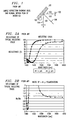
- FIG. 1 shows a polarized beam 102 reflecting from surface 107 of a mirror 101.
- the plane of incidence 103 is defined as the plane that contains the incident and reflected beams 102 and 104, respectively, and is parallel to the surface of the paper. Plane of incidence 103 also contains normal 106 to surface 107 of mirror 101.
- the double headed arrows 105 depict p-polarized light where the electric field vector oscillates parallel to, i.e., within, the plane of incidence.
- the electric field vector of a s-polarized beam oscillates perpendicularly to the plane of incidence.
- the resulting power inaccuracy can be avoided by scrambling the incoming beam, by employing polarization diversity, or by passive compensation. Scrambling can be realized by varying the state of polarization in the temporal, spatial, or spectral domains. Scrambling is suited for laboratory applications and is typically not cost effective for applications such as channel monitoring.
- Polarization diversity involves routing the s and p polarization states through different optical paths such that the two states have equal insertion loss. This approach requires a complicated optical path that rarely fits in compact packages. Passive compensation utilizes an optical element that introduces polarization dependent loss (PDL) to undo the PDL of the tap.
- PDL polarization dependent loss
- the optical channel monitor uses passive compensation, wherein polarization induced power inaccuracy is avoided by reflecting the diffracted free space beam from a mirror.
- This mirror is positioned such that s-polarization at the grating becomes p-polarization at the mirror.
- the reflectance of this mirror must compensate grating PDL as a function of wavelength. This spectral dependence can be generated with complex dielectric thin film stacks.
- FIG. 2A plots the reflectance of the s and p polarization states near the high energy edge of a typical bandpass filter
- FIG. 2B shows the ratio of the two curves of FIG. 2A.
- the ratio in FIG, B can is used to compensate polarization in the C-band. Since the sharp spectral transition is subject to manufacturing variations, the compensation is often imprecise.
- applicant's invention is a reflective surface that compensates optical tap induced polarization by employing the intrinsic properties of transition metals rather than complex dielectric thin film stacks.
- a reflective surface is employed that is a prescribed transition metal film.
- a transition metal surface polished or otherwise, is employed.
- the metal is preferably tungsten because it exhibits a large difference in the spread of reflectance between the s and p polarization states.
- the spectral dependence and magnitude of the ratio of the reflectance (R) of the two polarization states s and p can be accurately matched by choosing amongst four degrees of freedom: selecting the correct transition metal; adjusting the angle at which the mirror or metal surface reflects a polarized light beam; adding a dielectric layer on top of the metal film; and/or using multiple mirrors or metal surfaces.
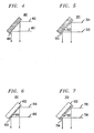
- FIGs. 3A, 3B, 3C and 3D show a Bragg grating 303 diffracting an incoming guided optical mode, i.e., beam, 302 within an optical fiber into a radiation mode in free space in an optical tap including an embodiment of the invention.
- incoming guided optical radiation 302 in this example, within an optical fiber, is directed to a blazed fiber Bragg grating 303 which diffracts it into optical radiation beam 304 in free space that is directed to reflective surface 301 having, in this example, a metalized film surface.
- the metalized film surface of reflective surface 301 employs the intrinsic properties of metals rather than the prior known dielectric thin film stack to compensate for the polarization induced by grating 303.
- double headed arrows 307 depict s-type polarization at grating 303 and in free space 304, i.e., electric field perpendicular to grating 303's plane of incidence. Since the reflective surface 301 reflects the free space beam out of the XZ plane along the Y direction as beam 305, the electric field is parallel to the plane of incidence at the reflective surface 301. As a result, s-polarization at the grating 303 becomes p-polarization at the reflective surface 301. Beam 305 is supplied to detector 306 for use as desired.
- FIG. 3B shows the X-Y plane portion of the embodiment shown in FIG. 3A. The only visual difference is that diffracted beam 304 is overlaid on the depiction of incoming guide beam 302.
- FIG. 3C shows the X-Z plane portion of the embodiment of FIG. 3A.
- the circled X depicts s-polarization at and from grating 303.
- the only visual difference being the portion shown in FIG. 3C and the embodiment shown in FIG. 3A is that the refection of the diffracted beam from reflective surface 301 is hidden by reflective surface 301.
- FIG. 3D shows an implementation similar to FIG. 3A except the reflective surface 301 of FIG. 3A is replaced by reflective surfaces 308 and 310, and light beam path 309.
- multiple reflective surfaces 308 and 310 are used sequentially to adjust the magnitude and spectral tilt of Rs/Rp.
- the first reflective surface 308 is used to adjust the average Rs/Rp level and the second reflective surface 310 generates spectral tilt in Rs/Rp.
- This combination of two reflective surfaces 308 and 310 allows one reflective surface 308 to generate a relatively large but spectrally flat Rs/Rp, while the other reflective surface 310 generates a relatively small but spectrally tilted Rs/Rp.
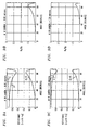
- FIG. 4 shows a reflective surface, i.e., mirror, comprising a metal substrate 401, polished or otherwise, which may be employed in practicing the invention. After being diffracted by the grating (see FIG. 3) optical beams 402 and 403 propagate in free space and are then reflected from surface 404 of metal substrate 401.
- a reflective surface i.e., mirror
- FIG. 5 shows a reflective surface 501, i.e., mirror, comprising a metal substrate 401 of FIG. 4 coated with a dielectric layer 503 that may be employed in practicing the invention. Also shown are diffracted optical beams 504 and 505 in free space being reflected from the outer dielectric surface 502 of dielectric layer 503.
- FIG. 6 shows a reflective surface, i.e., mirror, 601 comprising a glass substrate 602, polished or otherwise, coated with a prescribed thin metal film 603 that may be employed in practicing the invention. Also shown are diffracted optical beams 604 and 605 in free space being reflected from the outer metal film surface 606 of dielectric layer 603.
- FIG. 7 shows the reflective surface 701 including a glass substrate 601 polished or otherwise, and thin metal film 602 of FIG. 6 coated with a dielectric layer 704 that may be employed in practicing the invention. Also shown are diffracted optical beams 705 and 706 in free space being reflected from the outer dielectric surface 707 of dielectric layer 704.
- metals such as nickel and tungsten reflect s-polarized light much more strongly than p-polarized light.
- the noble metals copper, silver, and gold
- the two polarizations with nearly equal intensity while aluminum is an intermediate case. This is due to the relative size of the real and imaginary parts of the index of refraction (n).
- the relative size of the real and imaginary parts of the index of refraction is influenced by a competition between free and bound electrons.
- the imaginary index is high in metals dominated by free electrons, while the real and imaginary parts have roughly similar values in metals influenced by interband transitions (see the Handbook of Optical Constants of Solids by E.D. Palik, Academic Press, 1985).
- the above comments apply to bulk metals, for example, as shown in FIG. 4, and thin metal films deposited on smooth glass substrates, for example, as shown in FIG. 6.
- the thin metal film should have a thickness such that it is opaque to the wavelengths of interest.
- the thin metal film should have a thickness of about 1000 to 2000 Angstroms.
- the dielectric layer should have a thickness substantially equal to the wavelengths of interest.
- the films can be deposited on a substrate by standard techniques such as evaporation, sputtering, or chemical vapor deposition.
- the macroscopic dimensions of the reflective surface should be large enough to encompass the entire optical light beam at a desired angle of incidence.
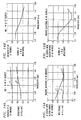
- FIG. 12A graphically shows reflectance (s, p) for tungsten versus wavelength at a first prescribed angle of incidence.
- FIG. 12B graphically illustrates the ratio Rs/Rp of s and p polarizations versus wavelength at the first prescribed angle of incidence for tungsten.
- FIG. 13A graphically shows reflectance (s, p) for tungsten versus wavelength at a second prescribed angle of incidence.
- FIG. 13B graphically illustrates the ratio Rs/Rp of s and p polarizations versus wavelength at the second prescribed angle of incidence for tungsten.
- FIG. 14A graphically shows reflectance (s, p) for tungsten versus wavelength at a third prescribed angle of incidence.
- FIG. 14B graphically illustrates the ratio Rs/Rp of s and p polarizations versus wavelength at the third prescribed angle of incidence for tungsten.
- the angle of incidence can also be used to adjust the magnitude of the Rs/Rp ratio for a given metal.
- the Rs/Rp ratio of a metal can be modified by a dielectric coating, see for example, FIGs. 5 and 7. If a few thousand Angstroms of silicon nitride are deposited on a metal surface, light reflects from both the air/dielectric and dielectric/metal interfaces. The interference of these reflections can be used to optimize the spectral distribution of the Rs/Rp ratio, see for example, FIGs. 15A & 15B.
- grating induced polarization dependent loss is a function of wavelength (for example - the ratio of the reflectance of the two polarizations, Rs/Rp, can vary from about 1.24 to 1.08 across the C-band).
- the spectral dependence and magnitude of Rs/Rp can be accurately matched by choosing amongst four degrees of freedom: selecting the correct metal, adjusting the angle at which the mirror surface reflects the polarized light beam, adding a dielectric layer on top of the metal film, and/or using multiple reflective surfaces.
- a tungsten coated mirror surface can nearly match a typical grating's Rs/Rp as a function of wavelength.
- Other transition metals such as Ni, Mo, V (vanadium), Fe, Ta), and transition metal compounds (such as TiC, TiN) generate a range of Rs/Rp ratios.
- Metallic alloys could also be used to adjust Rs/Rp for a given application. Metals with reflectance that range from moderate to high values over the spectral band of interest provide more spectral tilt in Rs/Rp.
- the angle of incidence at the reflective surface (angle between the normal 106 and incoming beam 102 in FIG. 1) can also be changed to alter Rs/Rp.
- FIG. 15B demonstrates a desirable Rs/Rp spectral dependence by using a tungsten reflective surface that has been coated with about 8000A of silicon nitride. Other coatings such as silicon dioxide and silicon can also be used. These types of bilayers have demonstrated impressive stability in other applications (photothermal solar conversion). Finally, multiple reflective surfaces can also be used sequentially to adjust the magnitude and spectral tilt of Rs/Rp.
- This reflective surface embodiment of the invention compensates the polarization of blazed fiber Bragg gratings such that the PDL of optical channel monitors (OCMs) and other optical taps can be held below, for example, 0.2 db.
- OCMs optical channel monitors
- metal films only need to be opaque, deposition conditions are easy to control.
- complex dielectric stacks under current use employ a sharp spectral edge to generate the desired Rs/Rp ratio. This sharp edge is difficult to control.
- the metal films therefore provide a more robust method for PDL compensation.
- large PDL values from gratings blazed at high angles can also be compensated with proper designs.
- channel monitors with dual grating designs an additional challenge due to the need for complex Rs/Rp spectral shapes
- metallic reflective surfaces can be suitably compensated with metallic reflective surfaces.
Landscapes
- Physics & Mathematics (AREA)
- General Physics & Mathematics (AREA)
- Optics & Photonics (AREA)
- Optical Elements Other Than Lenses (AREA)
- Polarising Elements (AREA)
- Optical Fibers, Optical Fiber Cores, And Optical Fiber Bundles (AREA)
- Diffracting Gratings Or Hologram Optical Elements (AREA)
- Optical Integrated Circuits (AREA)
Applications Claiming Priority (2)
| Application Number | Priority Date | Filing Date | Title |
|---|---|---|---|
| US10/269,022 US6807004B2 (en) | 2002-10-10 | 2002-10-10 | Polarization independent optical taps |
| US269022 | 2002-10-10 |
Publications (2)
| Publication Number | Publication Date |
|---|---|
| EP1408355A1 EP1408355A1 (en) | 2004-04-14 |
| EP1408355B1 true EP1408355B1 (en) | 2006-10-11 |
Family
ID=32030373
Family Applications (1)
| Application Number | Title | Priority Date | Filing Date |
|---|---|---|---|
| EP03254965A Expired - Lifetime EP1408355B1 (en) | 2002-10-10 | 2003-08-09 | Polarization compensated optical tap |
Country Status (7)
| Country | Link |
|---|---|
| US (1) | US6807004B2 (https=) |
| EP (1) | EP1408355B1 (https=) |
| JP (1) | JP4542321B2 (https=) |
| KR (1) | KR100990324B1 (https=) |
| AT (1) | ATE342519T1 (https=) |
| DE (1) | DE60308975T2 (https=) |
| DK (1) | DK1408355T3 (https=) |
Families Citing this family (5)
| Publication number | Priority date | Publication date | Assignee | Title |
|---|---|---|---|---|
| US6807004B2 (en) * | 2002-10-10 | 2004-10-19 | Lucent Technologies Inc. | Polarization independent optical taps |
| US7171085B2 (en) * | 2003-07-29 | 2007-01-30 | Jds Uniphase Corporation | Polarization compensated optical tap |
| KR200454188Y1 (ko) * | 2009-04-20 | 2011-06-21 | 김학율 | 낙하물 방지용 안전발판 보조장치 |
| WO2013029178A1 (en) * | 2011-09-02 | 2013-03-07 | UNIVERSITé LAVAL | Polarization-maintaining module for making optical systems polarization-independent |
| NL2025012A (en) * | 2019-03-13 | 2020-09-17 | Asml Holding Nv | Lithographic apparatus, metrology apparatus, optical system and method |
Family Cites Families (17)
| Publication number | Priority date | Publication date | Assignee | Title |
|---|---|---|---|---|
| US2731881A (en) * | 1956-01-24 | Prism system for binocular tubes | ||
| GB1362181A (en) | 1971-07-08 | 1974-07-30 | Martin D H | Variation of the polarization of an electro-magnetic wave |
| FR2257914B1 (https=) * | 1972-11-20 | 1976-04-30 | Sopelem | |
| JPS59156929A (ja) * | 1983-02-22 | 1984-09-06 | Showa Electric Wire & Cable Co Ltd | 偏波面保存フアイバ用プリフオ−ムの製造方法 |
| JPS59172624A (ja) * | 1983-03-23 | 1984-09-29 | Hitachi Ltd | 光偏向走査装置 |
| US4751720A (en) * | 1987-04-03 | 1988-06-14 | Spectra-Physics, Inc. | Cube corner polarizer |
| JPH02109086A (ja) * | 1988-10-18 | 1990-04-20 | Canon Inc | ホログラム焼付装置 |
| US5333090A (en) * | 1992-10-13 | 1994-07-26 | Coherent, Inc. | Optical coating for reflecting visible and longer wavelength radiation having grazing incidence angle |
| JP2959327B2 (ja) | 1993-05-24 | 1999-10-06 | 富士通株式会社 | 光モニター装置 |
| CA2153345C (en) * | 1994-12-15 | 2000-01-11 | Robert William Filas | Low polarization sensitivity gold mirrors on silica |
| US5608521A (en) * | 1995-09-18 | 1997-03-04 | Trw Inc. | Polarization compensated imaging spectrometer |
| JP3642840B2 (ja) * | 1995-10-17 | 2005-04-27 | 富士通株式会社 | モニタリング用光デバイス |
| US5832156A (en) | 1996-10-31 | 1998-11-03 | Lucent Technologies Inc. | Article comprising an optical waveguide tap |
| US6122422A (en) | 1998-06-08 | 2000-09-19 | Lucent Technologies Inc. | Article comprising a dispersive waveguide tap |
| JP4427837B2 (ja) | 1999-09-03 | 2010-03-10 | 住友化学株式会社 | ワイヤーグリッド型偏光光学素子 |
| US6385369B1 (en) * | 1999-11-29 | 2002-05-07 | Her Majesty The Queen In Right Of Canada As Represented By The Minister Of Industry | Method and device for reducing polarization dependence in an optical component or optical system |
| US6807004B2 (en) * | 2002-10-10 | 2004-10-19 | Lucent Technologies Inc. | Polarization independent optical taps |
-
2002
- 2002-10-10 US US10/269,022 patent/US6807004B2/en not_active Expired - Lifetime
-
2003
- 2003-08-09 DK DK03254965T patent/DK1408355T3/da active
- 2003-08-09 EP EP03254965A patent/EP1408355B1/en not_active Expired - Lifetime
- 2003-08-09 AT AT03254965T patent/ATE342519T1/de not_active IP Right Cessation
- 2003-08-09 DE DE60308975T patent/DE60308975T2/de not_active Expired - Lifetime
- 2003-08-19 JP JP2003295431A patent/JP4542321B2/ja not_active Expired - Fee Related
- 2003-08-21 KR KR1020030057876A patent/KR100990324B1/ko not_active Expired - Fee Related
Also Published As
| Publication number | Publication date |
|---|---|
| KR100990324B1 (ko) | 2010-10-29 |
| DK1408355T3 (da) | 2007-01-29 |
| KR20040032740A (ko) | 2004-04-17 |
| DE60308975D1 (de) | 2006-11-23 |
| JP2004133418A (ja) | 2004-04-30 |
| US6807004B2 (en) | 2004-10-19 |
| DE60308975T2 (de) | 2007-06-14 |
| US20040070830A1 (en) | 2004-04-15 |
| JP4542321B2 (ja) | 2010-09-15 |
| ATE342519T1 (de) | 2006-11-15 |
| EP1408355A1 (en) | 2004-04-14 |
Similar Documents
| Publication | Publication Date | Title |
|---|---|---|
| USRE43965E1 (en) | Compensating for chromatic dispersion in optical fibers | |
| US6754006B2 (en) | Hybrid metallic-dielectric grating | |
| Bland-Hawthorn et al. | Instruments without optics: an integrated photonic spectrograph | |
| US6128133A (en) | Optical beamsplitter | |
| US6392775B1 (en) | Optical reflector for micro-machined mirrors | |
| Böni | Supermirror-based beam devices | |
| US6804063B2 (en) | Optical interference filter having parallel phase control elements | |
| US20030161024A1 (en) | Dual fibers coupled to an etalon | |
| EP1408355B1 (en) | Polarization compensated optical tap | |
| US7139128B2 (en) | Diffraction grating having high throughput efficiency | |
| US20010038729A1 (en) | System comprising in-line wavelength sensitive polarimeter | |
| US4662722A (en) | Polarization insensitive mirror | |
| FR2942549A1 (fr) | Reseau de diffraction polarisant, coupleur a reseau de diffraction polarisant et systeme planaire d'imagerie ou de transport de faisceau optique a coupleurs diffractifs polarisants | |
| CA2335670C (en) | Light waveguide with integrated input aperture for an optical spectrometer | |
| US5973835A (en) | Multilayer thin-film broad-band polarizing beam-splitter | |
| US8120863B2 (en) | Device for sampling a plurality of parts of a light beam | |
| JPH03261846A (ja) | 赤外線吸収強化分光装置 | |
| EP1333309A2 (en) | Dispersion compensator with flattened transmission band | |
| US20130094087A1 (en) | Tunable filter using a wave plate | |
| US20040036888A1 (en) | Interferometer having improved modulation depth and free-spectral range and method of manufacturing | |
| EP1668398B1 (en) | Method and device for reduction of polarization-dependent effects in a tunable optical component | |
| Moreau et al. | Capability and limits of the technology of complex optical interference filters | |
| Wang | Coupling to surface plasmon waves by the use of a birefringent prism coupler | |
| CA2393924A1 (en) | Optical polarizing device and laser polarisation device | |
| Favot et al. | Improved coatings for HF overtone lasers |
Legal Events
| Date | Code | Title | Description |
|---|---|---|---|
| PUAI | Public reference made under article 153(3) epc to a published international application that has entered the european phase |
Free format text: ORIGINAL CODE: 0009012 |
|
| 17P | Request for examination filed |
Effective date: 20030825 |
|
| AK | Designated contracting states |
Kind code of ref document: A1 Designated state(s): AT BE BG CH CY CZ DE DK EE ES FI FR GB GR HU IE IT LI LU MC NL PT RO SE SI SK TR |
|
| AX | Request for extension of the european patent |
Extension state: AL LT LV MK |
|
| 17Q | First examination report despatched |
Effective date: 20040712 |
|
| AKX | Designation fees paid |
Designated state(s): AT BE BG CH CY CZ DE DK EE ES FI FR GB GR HU IE IT LI LU MC NL PT RO SE SI SK TR |
|
| GRAP | Despatch of communication of intention to grant a patent |
Free format text: ORIGINAL CODE: EPIDOSNIGR1 |
|
| GRAS | Grant fee paid |
Free format text: ORIGINAL CODE: EPIDOSNIGR3 |
|
| GRAA | (expected) grant |
Free format text: ORIGINAL CODE: 0009210 |
|
| AK | Designated contracting states |
Kind code of ref document: B1 Designated state(s): AT BE BG CH CY CZ DE DK EE ES FI FR GB GR HU IE IT LI LU MC NL PT RO SE SI SK TR |
|
| PG25 | Lapsed in a contracting state [announced via postgrant information from national office to epo] |
Ref country code: SK Free format text: LAPSE BECAUSE OF FAILURE TO SUBMIT A TRANSLATION OF THE DESCRIPTION OR TO PAY THE FEE WITHIN THE PRESCRIBED TIME-LIMIT Effective date: 20061011 Ref country code: BE Free format text: LAPSE BECAUSE OF FAILURE TO SUBMIT A TRANSLATION OF THE DESCRIPTION OR TO PAY THE FEE WITHIN THE PRESCRIBED TIME-LIMIT Effective date: 20061011 Ref country code: IT Free format text: LAPSE BECAUSE OF FAILURE TO SUBMIT A TRANSLATION OF THE DESCRIPTION OR TO PAY THE FEE WITHIN THE PRESCRIBED TIME-LIMIT;WARNING: LAPSES OF ITALIAN PATENTS WITH EFFECTIVE DATE BEFORE 2007 MAY HAVE OCCURRED AT ANY TIME BEFORE 2007. THE CORRECT EFFECTIVE DATE MAY BE DIFFERENT FROM THE ONE RECORDED. Effective date: 20061011 Ref country code: CH Free format text: LAPSE BECAUSE OF FAILURE TO SUBMIT A TRANSLATION OF THE DESCRIPTION OR TO PAY THE FEE WITHIN THE PRESCRIBED TIME-LIMIT Effective date: 20061011 Ref country code: RO Free format text: LAPSE BECAUSE OF FAILURE TO SUBMIT A TRANSLATION OF THE DESCRIPTION OR TO PAY THE FEE WITHIN THE PRESCRIBED TIME-LIMIT Effective date: 20061011 Ref country code: SI Free format text: LAPSE BECAUSE OF FAILURE TO SUBMIT A TRANSLATION OF THE DESCRIPTION OR TO PAY THE FEE WITHIN THE PRESCRIBED TIME-LIMIT Effective date: 20061011 Ref country code: NL Free format text: LAPSE BECAUSE OF FAILURE TO SUBMIT A TRANSLATION OF THE DESCRIPTION OR TO PAY THE FEE WITHIN THE PRESCRIBED TIME-LIMIT Effective date: 20061011 Ref country code: AT Free format text: LAPSE BECAUSE OF FAILURE TO SUBMIT A TRANSLATION OF THE DESCRIPTION OR TO PAY THE FEE WITHIN THE PRESCRIBED TIME-LIMIT Effective date: 20061011 Ref country code: FI Free format text: LAPSE BECAUSE OF FAILURE TO SUBMIT A TRANSLATION OF THE DESCRIPTION OR TO PAY THE FEE WITHIN THE PRESCRIBED TIME-LIMIT Effective date: 20061011 Ref country code: CZ Free format text: LAPSE BECAUSE OF FAILURE TO SUBMIT A TRANSLATION OF THE DESCRIPTION OR TO PAY THE FEE WITHIN THE PRESCRIBED TIME-LIMIT Effective date: 20061011 Ref country code: LI Free format text: LAPSE BECAUSE OF FAILURE TO SUBMIT A TRANSLATION OF THE DESCRIPTION OR TO PAY THE FEE WITHIN THE PRESCRIBED TIME-LIMIT Effective date: 20061011 |
|
| REG | Reference to a national code |
Ref country code: GB Ref legal event code: FG4D |
|
| REG | Reference to a national code |
Ref country code: CH Ref legal event code: EP |
|
| REG | Reference to a national code |
Ref country code: IE Ref legal event code: FG4D |
|
| REF | Corresponds to: |
Ref document number: 60308975 Country of ref document: DE Date of ref document: 20061123 Kind code of ref document: P |
|
| PG25 | Lapsed in a contracting state [announced via postgrant information from national office to epo] |
Ref country code: SE Free format text: LAPSE BECAUSE OF FAILURE TO SUBMIT A TRANSLATION OF THE DESCRIPTION OR TO PAY THE FEE WITHIN THE PRESCRIBED TIME-LIMIT Effective date: 20070111 Ref country code: BG Free format text: LAPSE BECAUSE OF FAILURE TO SUBMIT A TRANSLATION OF THE DESCRIPTION OR TO PAY THE FEE WITHIN THE PRESCRIBED TIME-LIMIT Effective date: 20070111 |
|
| PG25 | Lapsed in a contracting state [announced via postgrant information from national office to epo] |
Ref country code: ES Free format text: LAPSE BECAUSE OF FAILURE TO SUBMIT A TRANSLATION OF THE DESCRIPTION OR TO PAY THE FEE WITHIN THE PRESCRIBED TIME-LIMIT Effective date: 20070122 |
|
| REG | Reference to a national code |
Ref country code: DK Ref legal event code: T3 |
|
| PG25 | Lapsed in a contracting state [announced via postgrant information from national office to epo] |
Ref country code: PT Free format text: LAPSE BECAUSE OF FAILURE TO SUBMIT A TRANSLATION OF THE DESCRIPTION OR TO PAY THE FEE WITHIN THE PRESCRIBED TIME-LIMIT Effective date: 20070319 |
|
| NLV1 | Nl: lapsed or annulled due to failure to fulfill the requirements of art. 29p and 29m of the patents act | ||
| ET | Fr: translation filed | ||
| REG | Reference to a national code |
Ref country code: CH Ref legal event code: PL |
|
| PLBE | No opposition filed within time limit |
Free format text: ORIGINAL CODE: 0009261 |
|
| STAA | Information on the status of an ep patent application or granted ep patent |
Free format text: STATUS: NO OPPOSITION FILED WITHIN TIME LIMIT |
|
| 26N | No opposition filed |
Effective date: 20070712 |
|
| PG25 | Lapsed in a contracting state [announced via postgrant information from national office to epo] |
Ref country code: MC Free format text: LAPSE BECAUSE OF NON-PAYMENT OF DUE FEES Effective date: 20070831 Ref country code: GR Free format text: LAPSE BECAUSE OF FAILURE TO SUBMIT A TRANSLATION OF THE DESCRIPTION OR TO PAY THE FEE WITHIN THE PRESCRIBED TIME-LIMIT Effective date: 20070112 |
|
| PG25 | Lapsed in a contracting state [announced via postgrant information from national office to epo] |
Ref country code: EE Free format text: LAPSE BECAUSE OF FAILURE TO SUBMIT A TRANSLATION OF THE DESCRIPTION OR TO PAY THE FEE WITHIN THE PRESCRIBED TIME-LIMIT Effective date: 20061011 Ref country code: IE Free format text: LAPSE BECAUSE OF NON-PAYMENT OF DUE FEES Effective date: 20070809 |
|
| PGFP | Annual fee paid to national office [announced via postgrant information from national office to epo] |
Ref country code: DK Payment date: 20080814 Year of fee payment: 6 |
|
| PGFP | Annual fee paid to national office [announced via postgrant information from national office to epo] |
Ref country code: IT Payment date: 20080822 Year of fee payment: 6 |
|
| PG25 | Lapsed in a contracting state [announced via postgrant information from national office to epo] |
Ref country code: LU Free format text: LAPSE BECAUSE OF NON-PAYMENT OF DUE FEES Effective date: 20070809 Ref country code: CY Free format text: LAPSE BECAUSE OF FAILURE TO SUBMIT A TRANSLATION OF THE DESCRIPTION OR TO PAY THE FEE WITHIN THE PRESCRIBED TIME-LIMIT Effective date: 20061011 |
|
| PG25 | Lapsed in a contracting state [announced via postgrant information from national office to epo] |
Ref country code: HU Free format text: LAPSE BECAUSE OF FAILURE TO SUBMIT A TRANSLATION OF THE DESCRIPTION OR TO PAY THE FEE WITHIN THE PRESCRIBED TIME-LIMIT Effective date: 20070412 Ref country code: TR Free format text: LAPSE BECAUSE OF FAILURE TO SUBMIT A TRANSLATION OF THE DESCRIPTION OR TO PAY THE FEE WITHIN THE PRESCRIBED TIME-LIMIT Effective date: 20061011 |
|
| REG | Reference to a national code |
Ref country code: DK Ref legal event code: EBP |
|
| PG25 | Lapsed in a contracting state [announced via postgrant information from national office to epo] |
Ref country code: DK Free format text: LAPSE BECAUSE OF NON-PAYMENT OF DUE FEES Effective date: 20090831 |
|
| PG25 | Lapsed in a contracting state [announced via postgrant information from national office to epo] |
Ref country code: IT Free format text: LAPSE BECAUSE OF NON-PAYMENT OF DUE FEES Effective date: 20090809 |
|
| REG | Reference to a national code |
Ref country code: GB Ref legal event code: 732E Free format text: REGISTERED BETWEEN 20131031 AND 20131106 |
|
| REG | Reference to a national code |
Ref country code: FR Ref legal event code: CD Owner name: ALCATEL-LUCENT USA INC. Effective date: 20131122 |
|
| REG | Reference to a national code |
Ref country code: FR Ref legal event code: GC Effective date: 20140410 |
|
| REG | Reference to a national code |
Ref country code: FR Ref legal event code: RG Effective date: 20141015 |
|
| REG | Reference to a national code |
Ref country code: FR Ref legal event code: PLFP Year of fee payment: 13 |
|
| REG | Reference to a national code |
Ref country code: FR Ref legal event code: PLFP Year of fee payment: 14 |
|
| REG | Reference to a national code |
Ref country code: FR Ref legal event code: PLFP Year of fee payment: 15 |
|
| REG | Reference to a national code |
Ref country code: FR Ref legal event code: PLFP Year of fee payment: 16 |
|
| REG | Reference to a national code |
Ref country code: GB Ref legal event code: 732E Free format text: REGISTERED BETWEEN 20190131 AND 20190206 |
|
| REG | Reference to a national code |
Ref country code: DE Ref legal event code: R081 Ref document number: 60308975 Country of ref document: DE Owner name: PROVENANCE ASSET GROUP LLC, PITTSFORD, US Free format text: FORMER OWNER: LUCENT TECHNOLOGIES INC., MURRAY HILL, N.J., US |
|
| REG | Reference to a national code |
Ref country code: DE Ref legal event code: R081 Ref document number: 60308975 Country of ref document: DE Owner name: PROVENANCE ASSET GROUP LLC, PITTSFORD, US Free format text: FORMER OWNER: NOKIA OF AMERICA CORP. (N. D. GES. D. STAATES DELAWARE), MURRAY HILL, NJ, US Ref country code: DE Ref legal event code: R081 Ref document number: 60308975 Country of ref document: DE Owner name: PROVENANCE ASSET GROUP LLC, PITTSFORD, US Free format text: FORMER OWNER: ALCATEL-LUCENT USA INC. (N. D. GES. D. STAATES DELAWARE), MURRAY HILL, N.J., US |
|
| PGFP | Annual fee paid to national office [announced via postgrant information from national office to epo] |
Ref country code: FR Payment date: 20190822 Year of fee payment: 17 |
|
| PGFP | Annual fee paid to national office [announced via postgrant information from national office to epo] |
Ref country code: DE Payment date: 20200901 Year of fee payment: 18 Ref country code: GB Payment date: 20200909 Year of fee payment: 18 |
|
| PG25 | Lapsed in a contracting state [announced via postgrant information from national office to epo] |
Ref country code: FR Free format text: LAPSE BECAUSE OF NON-PAYMENT OF DUE FEES Effective date: 20200831 |
|
| REG | Reference to a national code |
Ref country code: DE Ref legal event code: R119 Ref document number: 60308975 Country of ref document: DE |
|
| GBPC | Gb: european patent ceased through non-payment of renewal fee |
Effective date: 20210809 |
|
| PG25 | Lapsed in a contracting state [announced via postgrant information from national office to epo] |
Ref country code: GB Free format text: LAPSE BECAUSE OF NON-PAYMENT OF DUE FEES Effective date: 20210809 Ref country code: DE Free format text: LAPSE BECAUSE OF NON-PAYMENT OF DUE FEES Effective date: 20220301 |