EP1408273A2 - Schutzvorrichtung zur Überwachung eines mit einem Bauteil zu bewegenden Schutzbereichs - Google Patents
Schutzvorrichtung zur Überwachung eines mit einem Bauteil zu bewegenden Schutzbereichs Download PDFInfo
- Publication number
- EP1408273A2 EP1408273A2 EP03018853A EP03018853A EP1408273A2 EP 1408273 A2 EP1408273 A2 EP 1408273A2 EP 03018853 A EP03018853 A EP 03018853A EP 03018853 A EP03018853 A EP 03018853A EP 1408273 A2 EP1408273 A2 EP 1408273A2
- Authority
- EP
- European Patent Office
- Prior art keywords
- light
- light beam
- transmitted light
- component
- divergent
- Prior art date
- Legal status (The legal status is an assumption and is not a legal conclusion. Google has not performed a legal analysis and makes no representation as to the accuracy of the status listed.)
- Withdrawn
Links
- 238000012544 monitoring process Methods 0.000 title claims abstract description 21
- 238000005452 bending Methods 0.000 claims abstract description 77
- 238000000034 method Methods 0.000 claims abstract description 9
- 230000000670 limiting effect Effects 0.000 claims description 87
- 230000033001 locomotion Effects 0.000 claims description 57
- 230000001681 protective effect Effects 0.000 claims description 43
- 230000036961 partial effect Effects 0.000 claims description 16
- 230000005540 biological transmission Effects 0.000 claims description 14
- 238000011156 evaluation Methods 0.000 claims description 14
- 238000007493 shaping process Methods 0.000 claims description 7
- 230000002829 reductive effect Effects 0.000 abstract description 3
- 108091008695 photoreceptors Proteins 0.000 abstract 1
- 230000015572 biosynthetic process Effects 0.000 description 3
- 208000027418 Wounds and injury Diseases 0.000 description 2
- 238000013459 approach Methods 0.000 description 2
- 230000006378 damage Effects 0.000 description 2
- 208000014674 injury Diseases 0.000 description 2
- 230000005855 radiation Effects 0.000 description 2
- 230000004888 barrier function Effects 0.000 description 1
- 230000000903 blocking effect Effects 0.000 description 1
- 230000008859 change Effects 0.000 description 1
- 230000000295 complement effect Effects 0.000 description 1
- 230000007423 decrease Effects 0.000 description 1
- 230000003247 decreasing effect Effects 0.000 description 1
- 238000001514 detection method Methods 0.000 description 1
- 238000011161 development Methods 0.000 description 1
- 230000018109 developmental process Effects 0.000 description 1
- 230000000694 effects Effects 0.000 description 1
- 238000003754 machining Methods 0.000 description 1
- 238000004519 manufacturing process Methods 0.000 description 1
- 230000010355 oscillation Effects 0.000 description 1
- 230000008569 process Effects 0.000 description 1
- 230000009467 reduction Effects 0.000 description 1
Images


Classifications
-
- F—MECHANICAL ENGINEERING; LIGHTING; HEATING; WEAPONS; BLASTING
- F16—ENGINEERING ELEMENTS AND UNITS; GENERAL MEASURES FOR PRODUCING AND MAINTAINING EFFECTIVE FUNCTIONING OF MACHINES OR INSTALLATIONS; THERMAL INSULATION IN GENERAL
- F16P—SAFETY DEVICES IN GENERAL; SAFETY DEVICES FOR PRESSES
- F16P3/00—Safety devices acting in conjunction with the control or operation of a machine; Control arrangements requiring the simultaneous use of two or more parts of the body
- F16P3/12—Safety devices acting in conjunction with the control or operation of a machine; Control arrangements requiring the simultaneous use of two or more parts of the body with means, e.g. feelers, which in case of the presence of a body part of a person in or near the danger zone influence the control or operation of the machine
- F16P3/14—Safety devices acting in conjunction with the control or operation of a machine; Control arrangements requiring the simultaneous use of two or more parts of the body with means, e.g. feelers, which in case of the presence of a body part of a person in or near the danger zone influence the control or operation of the machine the means being photocells or other devices sensitive without mechanical contact
- F16P3/144—Safety devices acting in conjunction with the control or operation of a machine; Control arrangements requiring the simultaneous use of two or more parts of the body with means, e.g. feelers, which in case of the presence of a body part of a person in or near the danger zone influence the control or operation of the machine the means being photocells or other devices sensitive without mechanical contact using light grids
-
- B—PERFORMING OPERATIONS; TRANSPORTING
- B21—MECHANICAL METAL-WORKING WITHOUT ESSENTIALLY REMOVING MATERIAL; PUNCHING METAL
- B21D—WORKING OR PROCESSING OF SHEET METAL OR METAL TUBES, RODS OR PROFILES WITHOUT ESSENTIALLY REMOVING MATERIAL; PUNCHING METAL
- B21D55/00—Safety devices protecting the machine or the operator, specially adapted for apparatus or machines dealt with in this subclass
-
- G—PHYSICS
- G01—MEASURING; TESTING
- G01V—GEOPHYSICS; GRAVITATIONAL MEASUREMENTS; DETECTING MASSES OR OBJECTS; TAGS
- G01V8/00—Prospecting or detecting by optical means
- G01V8/10—Detecting, e.g. by using light barriers
Definitions
- the present invention relates to a protective device for attachment on a moving component along a path and for monitoring a to be moved with the component to the protection area and a method to monitor a protected area, one along a path move moving component is mitzubewegen.
- FIG. 1 schematically partially shown die-bending press, one of a not shown in Fig. 1 Drive device driven bending tool 10, for example with a V-shaped underside, and a stationary lower tool 12, the upper side, for example, one of the shape of Bottom of the bending tool 10 may have corresponding V-groove.
- To achieve a short cycle time is the bending tool 10 from an initial position at high speed moves toward the workpiece 14 along a direction of movement B, but then slowed down again, leaving it with one for the bending process suitable, lower speed impinges on the workpiece 14 and press this into the lower tool 12.
- the slowing down of the movement of the bending tool 10 can u. a. not because of its inertia instantaneously.
- the route necessary to the bending tool 10 from slow speed to a stop is also called Nachlaufweg N.
- the workpieces 14 in the die-bending press are inserted, are on two support arms 16 and 18, a light emitter 20 and a Light receiver 22 attached, which together form a through-beam sensor form.
- the evaluation electronics is designed so that when interrupting the light path between the light transmitter 20 and the light receiver 22, a signal to the Drive device is deliverable, so that this the movement of the bending tool 10 brakes as fast as possible. That of the light transmitter 20 emitted, parallel transmitted light bundles therefore defines a protected area, the corresponding due to its the size of the trailing distance N. Distance from the bottom of the bending tool 10 an injury prevents a person.
- a receiving area of the light receiver 22 are increased so that the transmitted light beam 27 of the light transmitter 20 at vibrations not so easy from the light receiver 22 emigrated. Then, however, the case may occur that the Presence of a body part of a person between the bending tool 10 and the workpiece 14, in Fig. 1, for example, near the light receiver 22, is not noticeable, although it is at a distance within the caster N under the bending tool 10 is located. This then means a reduction in occupational safety.
- So secured die bending presses therefore have the disadvantage that they either entail increased safety risks for the operating personnel or have undesirably high downtime.
- the present invention is therefore based on the object, a Protective device for attachment to a movable along a path Component and for monitoring a to be moved with the component Provide a protection zone that has good reliability, and specify a procedure for monitoring a protected area, to move along with a moved along a path component is.
- the object is further achieved by a method for monitoring a protection area with the features of claim 16.
- a divergent transmit light beam is sent out and with the Moving component, the divergent transmitted light bundle after covering a light path encompassing the protection area on a with the component moving, the width of the protection area in at least one direction limited, less divergent reception light beam and it the received light beam is received and monitored.
- the protection device according to the invention is intended for attachment to this component.
- a divergent transmitted light beam is emitted and moved with the component.
- the light emitter for the radiation of divergent transmitted light bundle in a protective area containing Space area provided so that both this space area as well the transmitted light bundle with the component are mitbewegbar.
- the light transmitter can be a light source, for example, for light in the visible or infrared wavelength range of the light, and possibly a transmission optics for shaping of the divergent transmitted light beam emitted from the light source Include light.
- the transmitted light bundle is in at least a direction of divergence, i. in particular a sectional plane through the Transmitted light bundle along a propagation direction of the light, divergent.
- the inventive limitation of the transmitted light beam takes place in the protection device according to the invention by the limiting device, which is arranged so that the transmitted light bundle at the earliest Covering a path containing the protection area in the direction of Divergence of the transmitted light beam is limited. Also the limitation device is therefore mitbewegbar with the component and in particular to this durable.
- a partial beam of the light determined by the limiting device the divergent transmit beam will continue to be after the limit Received as with the component mitbewegtes received light beam and supervised.
- This is used in the inventive device to the component to be fastened and then mitbewegbare with the component Light receiver, which for this purpose a photodetection element for light of Light transmitter and optionally a receiving optics for focusing of the received light beam on the photodetection element can.
- divergent transmitted light bundles does not define the scope of protection according to the invention but contains it just.
- the determination of the scope is rather by the fact that the divergent transmitted light bundles after covering the protected area comprehensive light path on a the width of the protection area in at least one direction determining less divergent received light beam is limited.
- the received light beam can in particular also be parallel or even convergent.
- the concept of less divergent Receiving light bundle therefore closes in the context of the present invention these two alternatives.
- the limitation is so to speak from the divergent, i. fanned out transmit light bundle narrower, that is less divergent, defining the scope Partial bundle cut out after the limitation or the limiting device as with the component mitbewegtes received light beam is received and monitored.
- the limiting device determines the sub-beam of the Transmitted light beam between the light transmitter and the limiting device, that can be received by the light receiver as a reception light bundle is, thus defining the scope of protection.
- a transmitted light beam is used, at least is divergent in one direction tangential to the path of the component, including the light transmitter is to be aligned accordingly.
- the limitation occurs then at least in the same direction, which by appropriate Arrangement of the limiting device can be done. In this way The protection area can be moved in front of the component.
- the use of a divergent transmitted light beam allows a particularly simple adjustment of the light transmitter relative to the limiting device or the light receiver, as with a tilt of the Light transmitter compared to the light receiver only another sub-beam of the transmitted light bundle can be received as a received light bundle.
- An opening angle of the transmitted light beam, the divergence of the transmitted light beam determined in the Divergenzutter, preferably under other depending on the distance between the light emitter and the limiting device can be selected, since this distance together with the opening angle, the width of the transmitted light beam at the limiting device certainly. It is preferred that an opening angle of the transmitted light bundle is selected so that in a predetermined Direction orthogonal to the transmitted light path immediately before the limiting device a width of the transmitted light bundle by a factor 10 is greater than a corresponding width of the received light beam directly on the limiting device.
- Such a large divergence of the transmitted light bundle relative to that of the received light beam allows one Particularly simple adjustment and high reliability, in particular if, after mounting on the component, the specified direction is tangential is arranged to the web of the component.
- an opening angle of the transmitted light beam is chosen so that orthogonal in a given direction to the transmission light path immediately before the limiting device a Width of the transmitted light beam directly at the limiting device larger is as a by a relative movement of light emitter and limiting device caused, average expected movement amplitude the transmitted light beam directly to the limiting device. In this way, as much as possible with a given reliability Light of the light transmitter during operation of the protection device actually used to monitor the protected area.
- the limiting device can in principle comprise any means, by means of which the divergent transmitted light beam in its width in the predetermined direction can be limited to the received light beam.
- this may be a limitation of the photosensitive Act surface of the photodetection element.
- the limiting device comprises a diaphragm.
- Such Limiting device is particularly suitable for use in Through-beam sensors, i. in the event that the light emitter and the Light receiver on opposite sides of the protection area are arranged.
- shape and size of the transmitting light bundle limiting Aperture can be very easily set the scope become.
- the diaphragm can also be used as part of the light receiver be educated.
- a reflective element comprises, at which a the light receiver to be supplied sub-bundle of the divergent transmitted light bundle is reflective.
- the reflective for light of the light emitter Reflective element thus acts much like an aperture, just by clicking the surface of the reflective element incident light of the transmitted light beam is reflected as a received light beam. Size, shape and Orientation of the reflective surface, preferably by a for Light of the light transmitter is not surrounded or only slightly reflective area is, thereby determine the width or divergence of the received light beam and the direction in which the transmitted light beam is limited. In addition, it also allows a deflection of the light path.
- a retroreflective element comprises, at which a part of the bundle to be supplied to the light receiver divergent transmitted light beam is reflective.
- a retroreflective Element is understood here as an element, the incident light reflected back in the direction of the incident light.
- the retroreflective element may be a 90 ° prism, a Tripel reflector or corresponding reflective films act. Even with one Tilting of the retroreflective element with respect to the light emitter can so light will be thrown back towards the light transmitter.
- Analogous to the case of the reflective element of a limiting device determine also here the size, shape and orientation of the retroreflective Elements or its optically effective area the effect on the transmitted light bundle. The resulting received light beam can especially convergent.
- the protection device therefore comprises then a special reflection light barrier, preferably in the light transmitter and light receivers can be arranged in a housing.
- the arrangement of light emitter and light receiver on the same side The protection range allows in particular a particularly simple adjustment from light emitter and light receiver even before attachment to the Component.
- the light emitter and the light receiver has a common beam splitter and at least one in the transmission direction after the beam splitter arranged common Have transmit / receive lens.
- the beam splitter in particular a semitransparent mirror, while allowing a spatial separate arrangement of a light source of the light emitter and a photodetection element of the light receiver, although the transmitted light beam and the received light beam at least in the region of the transmitting / receiving lens overlap.
- a transmitting and receiving optics the protection device according to the invention at least partially integrated, which, especially in conjunction with a retroreflective Element as a limiting device, to a simple structure at simultaneous high accuracy of the beam guide leads.
- the light receiver at least one receiving element whose receiving surface is in a divergence direction of the received light beam corresponding to the direction in which the divergent one Transmitted light bundle was limited by the limiting device, has a greater extent than orthogonal in one direction to.
- This receiving element may in particular be a Act photodetection element.
- the received light beam in the divergence direction is not necessarily divergent but can also be parallel or convergent. To this Way, a wandering of the received light beam from a receiving area of the receiving element, by tilting the light transmitter and / or the light receiver or the limiting device with a reflective or retroreflective element is caused, be avoided at least at small tilt angles.
- the extent of the receiving element in the divergence direction is preferred of the received light beam by a factor of at least 4 greater than its extent in a direction orthogonal thereto.
- the light emitter preferably a transmission optics and / or the light receiver on a receiving optics.
- the light receiver has a slit whose slot parallel to a direction of divergence of the received light beam, that of the direction corresponds, in which the divergent transmitted light beam through the limiting device is limited, is arranged.
- the slot is here parallel to the divergence direction of the received light beam at the location of Slit aligned, that is, the direction of divergence with respect to the direction of the received light beam is defined.
- the transmitted light beam according to the invention needs only in one direction to be divergent, preferably tangential to the web along which the component is moved, is aligned. It can become a lot narrower, i. almost linear protection area result. For many applications However, it is desirable that a flat area of protection is monitored. It is therefore preferable that the light emitter is formed is that from him a Sendelichtbündel is deliverable, in two to each other orthogonal directions diverged to different degrees.
- the Send light bundle in an orthogonal direction for example be chosen much more divergent, so that a more planar Protection range results, the surface normal preferably tangential to the path of the component is.
- the light emitter and the limiting device for monitoring one in a direction of movement of the component orthogonal direction substantially flat Protected area are formed.
- the limiting device can thereby especially transverse to the direction in which it limits the transmitted light beam, have a greater extent than in the orthogonal thereto Direction.
- the light receiver with a diaphragm a butterfly-shaped aperture includes, which are arranged transversely to the direction in which the divergent transmitted light beam limited by the limiting device is.
- a minimum width of the aperture in about the size of the extension of a reflective or retroreflective element of the limiting device in the direction in the limiting device limits the divergent transmitted light beam.
- the position of the protection area in the limiting direction relative to the component is therefore durable.
- torsional vibrations act the limiting device, which has a corresponding inclination not strong.
- the edge area of the protection area the function is to approach from the side recognize, is there possibly occurring difference in the distance the protective field of the component in the limiting direction of less Importance.
- the limiting device comprises at least two reflective or retroreflective elements, which represent a coding. In this way is also a lateral resolution the protection zone is possible in zones.
- the reflective or retroreflective Elements are so inclined to each other that a drop of intensity the transmitting and / or receiving light beam in the direction of an edge of the light beam is substantially compensated.
- a drop of intensity the transmitting and / or receiving light beam in the direction of an edge of the light beam is substantially compensated.
- the light receiver This results in a uniformly illuminated protection area.
- zones of retroreflective elements in the image center area become by an angle different from perpendicular to them striking rays tilted.
- the amount of tilting of the retroreflective elements decreases to the edge of the picture down to zero. Due to the increasing tilt angle decreasing efficiency of retroreflection can be so imaged power in the image center area is reduced and that for pictures typical intensity drop to the edge of the image to be compensated.
- retroreflective elements can therefore be used in particular in the middle of the transmitted light bundle retroreflective elements opposite to the retroreflective at the edge of the transmitted light bundle Elements should be tilted so by a small angle that the corresponding Receive light bundle, in contrast to a received light bundle a retroreflective element at the edge of the transmitted light beam, only partly on the light receiver or a corresponding photosensitive Element falls in it.
- the light receiver is a linear array of photodetection elements having.
- a resolution also in a direction perpendicular to the path of the Component allows.
- the protective device preferably has an evaluation circuit for receiving received signals of the light receiver and for outputting corresponding monitoring signals. With these Monitoring signals can then in particular a drive for the moving Component to be controlled.
- Another object of the invention is a component for a device, with a drive device of the device on a predetermined Bahn is movable, and which is characterized in that at the Component is held a protective device according to the invention, wherein the Protective area comprises at least parts of the web.
- the protective device on the component held so that the Transmitted light bundle in one direction tangential to the path of the component diverges and that the limiting means the divergent transmitted light bundle also in a direction substantially tangential to the railway limited.
- the light transmitter and the limiting device at two spaced apart transversely to the web of the component holding arms are held on the component. This way can be very easy a protection area over the entire width of the component can be obtained.
- Another object of the invention is a shaping device, in particular a bending press, with a shaping tool, in particular bending tool, formed component according to the invention with a protective device according to the invention, wherein the protected area includes at least parts of the web.
- a shaping device in particular a bending press
- a shaping tool in particular bending tool
- a protective device according to the invention, wherein the protected area includes at least parts of the web.
- a die-bending press comprises a bending tool 32, which with a drive device, not shown in FIG. 2 along a predetermined linear path is movable in a direction of movement B, and a stationary lower tool 34 on which a workpiece 36 for machining is storable.
- the bending tool 32 has a V-shaped underside. Complementary to this underside of the bending tool 32 is the top of the lower tool 34 formed and has a corresponding V-shaped bending groove not shown in FIG. 2.
- a Protection device On attached to the bending tool 32 holding arms 38 and 40 is a Protection device according to the invention according to a first embodiment held the invention. This includes a held on the support arm 38 Light transmitter 42 and held on the support arm 40 light receiver 44, which via a line, not shown, with the drive means the die-bending press is connected.
- the light emitter 42 comprises in a housing a light source 46 in the form a red light or infrared light emitting diode and one in the emission direction arranged in front of the light source 46 transmitting optics 48th
- the transmitting optics 48 comprises at least one lens and is designed such that that light of the light-emitting diode 46 can be emitted as transmitted light bundle 50, in a direction parallel to the direction of movement B of the bending tool 32 is divergent.
- the light transmitter 42 is held on the holding arm 38 that the divergent transmitted light beam 50 in one direction substantially along the bottom of the bending tool 32 and parallel to it is radiant.
- the light emitter 42 has a light exit opening of the light emitter 42 a distance from the size of a caster N, as above is defined from a lower edge of the bending tool 32, so that also the transmitted light beam 50 on average this distance from the lower edge of the bending tool 32 has.
- the light receiver 44 comprises in a housing a shutter 52 as a limiting device, a receiving optics 54, a photodetecting element 56 for receiving red or infrared light of the light emitter 42 and for delivering respective receive signals and one with the photodetection element 56 connected evaluation circuit 57 for monitoring the received signals and output of monitoring signals the drive device.
- the transmitted light beam 50 traverses a corresponding mitbewegten with the bending tool Space area under the bending tool 32 and is characterized by the limiting device acting aperture 52 on a received light beam 58, which is much less divergent than the transmitted light beam 50.
- the received light beam 58 is then transmitted through the receiving optics 54 focused on the photodetection element 56.
- the photodetection element 56 receives the infrared light and places it in an electrical Signal to, which is monitored by the evaluation circuit 57.
- the evaluation circuit 57 enters in the absence of a received signal Alarm signal to the drive device for the bending tool 32 from, so that his movement is stopped.
- the diaphragm 52 thus leaves only a partial beam 60 of the transmitted light beam 50 happen, as a received light beam 58 via the receiving optics 54th the photodetection element 56 is supplied. Only if an object the sub-beam 60 of the divergent transmitted light beam 50 blocks no light is received from the light receiver 44, so that the Partial bundle 60 defined by an aperture of the aperture 52 hatched illustrated protection area 62 of the light emitter 42nd and the light receiver 44 formed protective device.
- tilting of the light transmitter 42 leads although to a correspondingly tilted divergent transmitted light bundle 50 ', but it is now through the aperture 52 as a limiting device another sub-beam 60 'of the divergent transmitted light beam 50' is transmitted, the relative to the bending tool 32, the same position and the Same width as the sub-bundle 60.
- the location of the protected area 62 relative to the bending tool 32 therefore remains even during movement of the Light transmitter 42 essentially unchanged.
- a movement of Light receiver 44 changes the position of the protection region 62 relative to the Bending tool 32 not essential because small movements of the light receiver 42 and thus the limiting device in the form of the aperture 52, unlike movements of the light transmitter 42, not one Pivoting the sub-bundle 60 lead, but at best to small Shifts.
- the in the figures used angles and lengths are, unless otherwise stated, only for better presentation and therefore not necessarily realistic.
- the light emitter 42 and the light receiver 44 on the support arms 38th and 40 are held so that the protection region 62 is substantially parallel to the lower edge of the bending tool 32 at a distance of the overrun path N runs, which designates the distance that is necessary to the bending tool 32 slow down to a maximum speed until standstill.
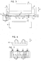
- Fig. 3 is a die-bending press with a protective device according to a second preferred embodiment of the invention, the only by the formation of the protective device of the first Example differs.
- the same components, especially the die-bending press are therefore the same Embodiments as in the previous embodiment and it the same reference numerals are used.
- the protection device now comprises a light transmitter and a light receiver, which is combined to a transmitting / receiving unit 64 and are held on the holding arm 38.
- a holder 66 on the support arm 40 is a limiting device in the form of a reflective Elements 68 arranged.
- the transmitting / receiving unit 64 comprises for the light transmitter as the light source a laser diode 69 for red light, a beam splitter 70 and a Transceiver optics 72 and for the light receiver next to Transceiver optics 72 and the beam splitter 70 another receiving optics 74, a photodetecting element 56 and an evaluation circuit 57.
- the photodetection element 56 and the evaluation circuit 57 are formed previously as in the embodiment.
- the beam splitter 70 is formed by a semitransparent mirror.
- the reflective element 68 is replaced by one for light of the laser diode 69 reflecting mirror, while the holder 66 does not light or only weakly reflected.
- light of the laser diode 69 is transmitted through the beam splitter 70 and the transmit / receive optics 72 to a divergent transmit beam 76 formed between the bending tool 32 and the lower tool 34 is blasted through and in a direction parallel to the direction of movement B of the bending tool 32 is divergent.
- the transmitted light beam 76 then strikes the reflective element 68 and the holder 66, wherein it is substantially only on the reflective Element 68 is reflected. Thus, it becomes a partial bundle 78 of the transmitted light bundle 76 as a receiving light beam 80 to the transmitting / receiving unit 64 thrown back.
- the width of the sub-beam 78 and that of the received light beam 80 are due to the expansion of the reflective Elements 68 parallel to the path of the bending tool 32, i. for example the direction of movement B, determined.
- the reflective element 68 provides So a limiting device in the context of the invention.
- the received light beam 80 is transmitted through the transceiver optics 72, the beam splitter 70 and the further receiving optics 74 on the photodetection element 56 focused or diverted.
- the reflecting element 68 and the transmitting / receiving unit 64 are in turn arranged so that the protection area 82 substantially parallel to the underside of the bending tool 32 at a distance from the overrun path N is arranged.
- the transmission-receiving optics 72 formed so that an opening angle ⁇ of the transmitted light beam 76 is so large that its width in a plane parallel to the reflective Element 68 directly on the reflective element 68 approximately ten times larger than the extension of the reflective element 68 in FIG this direction.
- the widths of the sub-beam 78 and the received light beam 80 directly on the reflective element are therefore, determined by the corresponding extent of the reflective element, for example, by a factor of 10 smaller than the width of the transmitted light beam 76 at this point.
- a die-bending press with a guard after a third preferred embodiment of the invention is partially in Figs. 4 to 7. It differs from the die bending press in the second embodiment by the formation of the limiting device and the formation of the transmitting / receiving unit. For same Components are therefore used the same reference numerals and it The comments on these components apply accordingly in this embodiment.
- a transmitter / receiver unit comprising a light transmitter and a light receiver 84, which is held on the arm 38, has a laser diode 69 for red light, a cylindrical lens 86, a beam splitter 70, a aspherical lens 88, a slit 90, a color filter 92 and a Line scan camera 94, which is connected to an evaluation circuit 96.
- the cylindrical lens 86 and the aspherical lens 88 are formed and arranged that light the laser diode 69 to one another in two orthogonal directions divergent transmitted light beam 98 is shaped the parallel to the direction of movement B of the bending tool 32 a Has opening angle ⁇ , which is smaller than a further opening angle ⁇ 'in a direction orthogonal to the direction of movement B.
- the aspherical lens 88 is further configured to receive Light after reflection at the beam splitter 70 through the slit 90 and the color filter 92 is focused on the line camera 94.
- the slit 90 has a slot 99, which in a plane through the holding arms 38 and 40 are arranged perpendicular to the direction of movement B. is.
- the color filter 92 which includes an interference filter, is for disposal Of foreign or Störlicht and is essentially only for light of Laser diode 69 permeable.
- the line scan camera 94 includes a plurality of elongated, transverse to their Longitudinal direction parallel to each other arranged photodetection elements 100 in CMOS or CCD technique (see Fig. 7) taken along its longitudinal axis a length of about 250 microns and in a direction transverse thereto have a length of about 12.5 microns (see Fig. 7).
- the line camera 94 is connected to the evaluation circuit 96, which from the photodetection elements 100 emitted upon receipt of light receives and monitors electrical signals. Upon detection of an interruption a light path is an alarm signal to the drive device of the bending tool 32 delivered.
- a held on the holder 66 on the support arm 40 limiting device 102 has parallel, flat rectangular retroreflective elements 104 (see Fig. 6), which are transverse to the linear path of the bending tool and thus the direction of movement B are arranged.
- the short sides The retroreflective elements are parallel to the direction of movement B aligned.
- a coding is formed.
- the retroreflective elements 104 are conventional formed from retroreflective sheeting.
- the opening angle ⁇ for example 1 ° and the opening angle ⁇ ', for example, be about 0 °.
- the retroreflective elements 104 reflect according to the coding a fan of sub-beams 106 into a fan of received light beams 108, which are now somewhat convergent due to retroreflection.
- the fan-shaped sub-beams 106 and receiving light beams 108 are the For clarity, in Fig. 5 only partially shown as a separate bundle.
- the transmission light beam 98 becomes parallel in a divergence direction to the direction of movement B through the retroreflective elements 104 whose short sides are aligned parallel to this Divergenzides are.
- Their extension in the direction of movement B is corresponding an expected average oscillation amplitude of the transmitting / receiving unit 84 chosen smaller by a factor of 10 than the width of the transmitted light beam 98 at the limiting device 102.
- the in the Receive light beam 108 reflected sub-beams 106 are therefore in one Direction parallel to the direction of motion less divergent than that Transmitted light beam 98.
- the width of the transmitted light beam 98 in the Divergence direction parallel to the direction of movement B at the limiting device 102 also greater than a width of the generated by the reflection Receiving light beam 108 directly to the limiting device 102nd
- the received light beams 108 are transmitted through the aspherical lens 88 passed through the slit 90 via the beam splitter 70.
- the slot 99 the slit 90 is parallel to a direction of divergence of the received light beams 108 arranged at the location of the slit, which is the direction corresponds to the transmitted light beam 98 through the limiting device 102 in the direction of movement B on the received light beam 108th was limited.
- the slot 99 is thus also perpendicular to the direction of movement B arranged.
- the slit 90 thus causes a Increasing the depth of field perpendicular to the direction of movement B of the Bending tool 32, but not one in a direction orthogonal thereto, which corresponds to the direction in which the divergent transmitted light beam 98 was limited parallel to the direction of movement B,
- FIG. 7 only schematically shown illustration of the retroreflective elements 104, so that a spatial Resolution in the search area perpendicular to the direction of movement B given is.
- the photodetection elements 100 are the For the sake of clarity, in comparison to the images of the retroreflective Elements 104 are shown too wide.
- the photodetection elements 104 are in their longitudinal directions parallel to the slot 99 and thus a Divergenzraum the received light beam 108 is arranged at the location of the photodetection elements 104, which corresponds to the direction in which the transmitted light beam 98 through the Limiter 102 in the direction of movement B on the received light beam 108 was limited. This can reduce the impact of vibration-induced movements of the limiting device 102 and thus the receiving light beam 108 parallel to the direction of movement B can be easily intercepted.
- a die-bending press with a protective device after a fourth preferred embodiment of the invention is partially in Figs. 8 and 9. It's essentially like the die-bending press in that formed third embodiment, so that for the same components the same reference numbers are used and the remarks to These components also in this embodiment be valid.
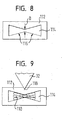
- an aperture 112 is provided which forms a butterfly-shaped aperture 114 (see Fig. 8).
- Two wing portions 116 of the aperture 114 are substantially parallel to the flat protective area 110 and thus arranged transversely to the direction of movement B or the direction, in which the divergent transmitted light beam 98 through the limiting device 102 is limited (see Fig. 9).
- a width D of a constriction of the aperture 114 corresponds to the Height of retroreflective elements 104 in the direction of travel B.
- the aperture 112 is at such a distance from a lower edge 118th of the bending tool 32, that the protective area 110 on the Height of the constriction of the aperture 114 is located and the received light beam These can happen (see Fig. 9).
- a misalignment in the angular position of the aperture 112 and the transmitting / receiving unit 84 to the limiting device 102 and thus the Protective area 110 does not necessarily lead to an interruption of the light path.
- the wing portions 114 are formed so that the receiving light beams 108 for misalignments by angles of up to about 3 ° still the aperture 112 can pass and a break the light path does not take place.
- the edge area of the protection area 110 has the function of recognizing an approach approaching the side are the different distances of the protection area 110 of the bending tool 32 in this area of little importance.
- Tilts caused by vibrations between the transmitting / receiving unit 84 and the limiting device along the lower edge 118 of the bending tool 32 do not affect negative because the retroreflective elements 104, the transmitted light beam 98 and the sub-beams 106 reflect essentially on itself. Furthermore, retroreflective sheeting has some degree of reflection Streuanteil on, by such misalignments also at least be partially compensated.
Landscapes
- Engineering & Computer Science (AREA)
- General Engineering & Computer Science (AREA)
- Mechanical Engineering (AREA)
- Physics & Mathematics (AREA)
- Life Sciences & Earth Sciences (AREA)
- General Life Sciences & Earth Sciences (AREA)
- General Physics & Mathematics (AREA)
- Geophysics (AREA)
- Presses And Accessory Devices Thereof (AREA)
- Geophysics And Detection Of Objects (AREA)
Abstract
Description
- Fig. 1
- eine schematische, teilweise Seitenansicht einer Gesenk-Biegepresse mit einer konventionellen Schutzvorrichtung,
- Fig. 2
- eine schematische teilweise Seitenansicht einer Gesenk-Biegepresse mit einer Schutzvorrichtung nach einer ersten bevorzugten Ausführungsform der Erfindung,
- Fig. 3
- eine schematische, teilweise Seitenansicht einer Gesenk-Biegepresse mit einer Schutzvorrichtung nach einer zweiten bevorzugten Ausführungsform der Erfindung,
- Fig. 4
- eine schematische, teilweise Seitenansicht von zwei Haltearmen mit einer Schutzvorrichtung einer Gesenk-Biegepresse nach einer dritten bevorzugten Ausführungsform der Erfindung,
- Fig. 5
- eine schematische teilweise Draufsicht auf die Schutzvorrichtung in Fig. 4,
- Fig. 6
- eine schematische Darstellung einer Begrenzungseinrichtung der Schutzvorrichtung in Fig. 4,
- Fig. 7
- eine schematische Darstellung von Photodetektionselementen in einem Lichtempfänger der Schutzvorrichtung in Fig. 4,
- Fig. 8
- eine schematische Darstellung einer Blende einer Schutzvorrichtung einer Gesenk-Biegepresse nach einer vierten bevorzugten Ausführungsform der Erfindung, und
- Fig. 9
- eine schematische Darstellung einer Schutzbereichslage in der Schutzvorrichtung in Fig. 8.
- 10
- Biegewerkzeug
- 12
- Unterwerkzeug
- 14
- Werkstück
- 16
- Haltearm
- 18
- Haltearm
- 20
- Lichtsender
- 22
- Lichtempfänger
- 24
- Lichtquelle
- 26
- Sendeoptik
- 27
- Sendelichtbündel
- 28
- Photodetektionselement mit Auswerteelektronik
- 30
- Empfangsoptik
- 32
- Biegewerkzeug
- 34
- Unterwerkzeug
- 36
- Werkstück
- 38
- Haltearm
- 40
- Haltearm
- 42
- Lichtsender
- 44
- Lichtempfänger
- 46
- Leuchtdiode
- 48
- Sendeoptik
- 50, 50'
- Sendelichtbündel
- 52
- Blende
- 54
- Empfangsoptik
- 56
- Photodetektionselement
- 57
- Auswerteschaltung
- 58
- Empfangslichtbündel
- 60,60'
- Teilbündel
- 62
- Schutzbereich
- 64
- Sende-/ Empfangseinheit
- 66
- Halter
- 68
- reflektierendes Element
- 69
- Laserdiode
- 70
- Strahlteiler
- 72
- Sende- und Empfangsoptik
- 74
- weitere Empfangsoptik
- 76
- Sendelichtbündel
- 78
- Teilbündel
- 80
- Empfangslichtbündel
- 82
- Schutzbereich
- 84
- Sende-/Empfangseinheit
- 86
- Zylinderlinse
- 88
- asphärische Linse
- 90
- Schlitzblende
- 92
- Farbfilter
- 94
- Zeilenkamera
- 96
- Auswerteinheit
- 98
- Sendelichtbündel
- 99
- Schlitz
- 100
- Photodetektionselemente
- 102
- Begrenzungseinrichtung
- 104
- retroreflektive Elemente
- 106
- Teilbündel
- 108
- Empfangslichtbündel
- 110
- Schutzbereich
- 112
- Blende
- 114
- Blendenöffnung
- 116
- Flügelbereiche
- 118
- Unterkante
- α, α'
- Öffnungswinkel
- B
- Bewegungsrichtung
- D
- Weite der Einschnürung
- N
- Nachlaufweg
Claims (17)
- Schutzvorrichtung zur Befestigung an einem entlang einer Bahn (B) beweglichen Bauteil (32) und zur Überwachung eines mit dem Bauteil (32) zu bewegenden Schutzbereichs (62; 82; 110) mit
einem Lichtsender (42; 64; 84) zur Abstrahlung eines divergenten Sendelichtbündels (50, 50'; 76; 98) in einen den Schutzbereich (62; 82; 110) enthaltenden Raumbereich,
einem Lichtempfänger (44; 64; 84) zum Empfang wenigstens eines Teils des Lichts des in den Raumbereich gestrahlten Sendelichtbündels (50, 50'; 76; 98) des Lichtsenders (42; 64; 84) und zur Abgabe entsprechender Empfangssignale, und
einer Begrenzungseinrichtung (52; 68; 102), die in Richtung eines Sendelichtweges hinter einem Abschnitt des Sendelichtweges, der den Schutzbereich (62; 82; 110) enthält, angeordnet ist und mittels derer das Sendelichtbündel (50, 50'; 76; 98) auf ein die Weite des Schutzbereichs (62; 82; 110) in wenigstens einer Richtung bestimmendes, weniger divergentes Empfangslichtbündel (58; 80; 108) begrenzbar ist. - Schutzvorrichtung nach Anspruch 1,
dadurch gekennzeichnet, dass ein Öffnungswinkel des Sendelichtbündels (50, 50'; 76; 98) so gewählt ist, dass in einer vorgegebenen Richtung orthogonal zum Sendelichtweg unmittelbar vor der Begrenzungseinrichtung (52; 68; 102) eine Weite des Sendelichtbündels (50, 50'; 76; 98) um einen Faktor 10 größer ist als eine entsprechende Weite des Empfangslichtbündels (58; 80; 108) direkt an der Begrenzungseinrichtung (52; 68; 102). - Schutzvorrichtung nach Anspruch 1 oder 2,
dadurch gekennzeichnet, dass ein Öffnungswinkel des Sendelichtbündels (50, 50'; 76; 98) so gewählt ist, dass in einer vorgegebenen Richtung orthogonal zum Sendelichtweg unmittelbar vor der Begrenzungseinrichtung (52; 68; 102) eine Weite des Sendelichtbündels (50, 50'; 76; 98) direkt an der Begrenzungseinrichtung (52; 68; 102) größer ist als eine durch eine Relativbewegung von Lichtsender (42; 64; 84) und Begrenzungseinrichtung (52; 68; 102) verursachte, mittlere zu erwartenden Bewegungsamplitude des Sendelichtbündels (50, 50'; 76; 98) unmittelbar an der Begrenzungseinrichtung (52; 68; 102). - Schutzvorrichtung nach einem der vorhergehenden Ansprüche,
dadurch gekennzeichnet, dass die Begrenzungseinrichtung eine Blende (52) umfasst. - Schutzvorrichtung nach einem der vorhergehenden Ansprüche,
dadurch gekennzeichnet, dass die Begrenzungseinrichtung ein reflektierendes Element (68) umfasst, an dem ein dem Lichtempfänger (44) zuzuführendes Teilbündel (78) des divergenten Sendelichtbündels (50, 50') reflektierbar ist, oder
dass die Begrenzungseinrichtung (102) ein retroreflektives Element (104) umfasst, an dem ein dem Lichtempfänger (84) zuzuführendes Teilbündel (106) des divergenten Sendelichtbündels (98) reflektierbar ist. - Schutzvorrichtung nach Anspruch 5,
dadurch gekennzeichnet, dass der Lichtsender (64; 84) und der Lichtempfänger (64; 84) auf der gleichen Seite des Schutzbereichs (82; 110) angeordnet sind, und
dass vorzugsweise der Lichtsender (64; 84) und der Lichtempfänger (64; 84) einen gemeinsamen Strahlteiler (70) und wenigstens eine in Senderichtung nach dem Strahlteiler (70) angeordnete gemeinsame Sende-/Empfangslinse (72; 88) aufweisen. - Schutzvorrichtung nach einem der vorhergehenden Ansprüche,
dadurch gekennzeichnet, dass der Lichtempfänger (44; 64; 84) wenigstens ein Empfangselement (100) aufweist, dessen Empfangsfläche in einer Divergenzrichtung des Empfangslichtbündels (58; 80; 108), die der Richtung (B) entspricht, in der das divergente Sendelichtbündel durch die Begrenzungseinrichtung (52; 68; 102) begrenzt wurde, eine größere Ausdehnung aufweist als in einer Richtung orthogonal dazu. - Schutzvorrichtung nach einem der vorhergehenden Ansprüche,
dadurch gekennzeichnet, dass der Lichtempfänger (84) eine Schlitzblende (90) aufweist, deren Schlitz (99) parallel zu einer Divergenzrichtung des Empfangslichtbündels (108), die der Richtung entspricht, in der das divergente Sendelichtbündel (98) durch die Begrenzungseinrichtung (102) begrenzbar ist, angeordnet ist. - Schutzvorrichtung nach einem der vorhergehenden Ansprüche,
dadurch gekennzeichnet, dass der Lichtsender (84) so ausgebildet ist, dass von ihm ein Sendelichtbündel (98) abgebbar ist, das in zwei zueinander orthogonalen Richtungen unterschiedlich stark divergiert, und
dass vorzugsweise der Lichtsender (84) und die Begrenzungseinrichtung (102) zur Überwachung eines in einer zu einer Bewegungsrichtung des Bauteils (32) orthogonalen Richtung flächigen Schutzbereichs (110) ausgebildet sind. - Schutzvorrichtung nach einem der vorhergehenden Ansprüche,
dadurch gekennzeichnet, dass der Lichtempfänger (84) eine Blende (112) mit einer schmetterlingsförmigen Blendenöffnung (114) aufweist, die zwei Flügelbereiche (116) umfasst, die quer zu der Richtung (B) angeordnet sind, in der das divergente Sendelichtbündel (98) durch die Begrenzungseinrichtung (102) begrenzbar ist. - Schutzvorrichtung nach einem der Ansprüche 9 oder 10 und einem der Ansprüche 5 oder 6 oder nach einem der Ansprüche 9 oder 10 und einem der Ansprüche 7 oder 8 und einem der Ansprüche 5 oder 6,
dadurch gekennzeichnet, dass die Begrenzungseinrichtung (102) wenigstens zwei reflektierende oder retroreflektive Elemente (104) umfasst, die eine Kodierung darstellen, und
dass die reflektierenden oder retroreflektiven Elemente (104) vorzugsweise so gegeneinander geneigt sind, dass ein Abfall einer Intensität des Sende- und/oder Empfangslichtbündels (98; 108) in Richtung eines Randes des Lichtbündels im Wesentlichen ausgleichbar ist. - Schutzvorrichtung nach einem der vorhergehenden Ansprüche,
dadurch gekennzeichnet, dass der Lichtempfänger (44; 64; 84) eine lineare Anordnung von Photodetektionselementen (100) aufweist. - Schutzvorrichtung nach einem der vorhergehenden Ansprüche, gekennzeichnet durch
eine Auswerteschaltung (57; 96) zum Empfang von Empfangssignalen des Lichtempfängers (44; 64; 84) und zur Ausgabe entsprechender Überwachungssignale. - Bauteil für eine Vorrichtung, das mit einer Antriebseinrichtung der Vorrichtung auf einer vorgegebenen Bahn (B) bewegbar ist,
dadurch gekennzeichnet, dass an dem Bauteil (32) eine Schutzvorrichtung nach einem der vorhergehenden Ansprüche gehalten ist, wobei der Schutzbereich (62; 82; 110) wenigstens Teile der Bahn (B) umfasst,
wobei insbesondere der Lichtsender (42; 64; 84) und die Begrenzungseinrichtung (52; 68; 102) an zwei räumlich quer zur Bahn (B) des Bauteils (32) beabstandeten Haltearmen (38, 40) an dem Bauteil (32) gehalten sind. - Formgebungsvorrichtung, insbesondere Biegepresse, mit einem als Formgebungswerkzeug, insbesondere Biegewerkzeug, ausgebildeten Bauteil nach Anspruch 14.
- Verfahren zur Überwachung eines Schutzbereichs (62; 82; 110), der mit einem entlang einer Bahn (B) bewegten Bauteil (32) mitzubewegen ist, bei dem
ein divergentes Sendelichtbündel (50, 50'; 76; 98) ausgesendet und mit dem Bauteil (32) mitbewegt wird,
das divergente Sendelichtbündel (50, 50'; 76; 98) nach Zurücklegen eines den Schutzbereich (62; 82; 110) umfassenden Lichtweges auf ein mit dem Bauteil (32) mitbewegtes, die Weite des Schutzbereichs (62; 82; 110) in wenigstens einer Richtung bestimmendes, weniger divergentes Empfangslichtbündel (58; 80; 108) begrenzt wird, und das Empfangslichtbündel (58; 80; 108) empfangen und überwacht wird. - Verfahren nach Anspruch 16,
dadurch gekennzeichnet, dass zur Begrenzung des Sendelichtbündels (50, 50'; 76; 98) ein reflektierendes Element (68) verwendet wird, oder
dass zur Begrenzung des Sendelichtbündels (50, 50'; 76; 98) ein retroreflektives Element (104) verwendet wird.
Applications Claiming Priority (2)
| Application Number | Priority Date | Filing Date | Title |
|---|---|---|---|
| DE10247136 | 2002-10-09 | ||
| DE10247136A DE10247136A1 (de) | 2002-10-09 | 2002-10-09 | Schutzvorrichtung zur Überwachung eines mit einem Bauteil zu bewegenden Schutzbereichs |
Publications (2)
| Publication Number | Publication Date |
|---|---|
| EP1408273A2 true EP1408273A2 (de) | 2004-04-14 |
| EP1408273A3 EP1408273A3 (de) | 2005-02-09 |
Family
ID=32010407
Family Applications (1)
| Application Number | Title | Priority Date | Filing Date |
|---|---|---|---|
| EP03018853A Withdrawn EP1408273A3 (de) | 2002-10-09 | 2003-08-19 | Schutzvorrichtung zur Überwachung eines mit einem Bauteil zu bewegenden Schutzbereichs |
Country Status (3)
| Country | Link |
|---|---|
| US (1) | US7034929B2 (de) |
| EP (1) | EP1408273A3 (de) |
| DE (1) | DE10247136A1 (de) |
Cited By (1)
| Publication number | Priority date | Publication date | Assignee | Title |
|---|---|---|---|---|
| CN114043185A (zh) * | 2021-11-29 | 2022-02-15 | 天津吉达尔重型机械科技股份有限公司 | 一种拉杆生产加工装置 |
Families Citing this family (16)
| Publication number | Priority date | Publication date | Assignee | Title |
|---|---|---|---|---|
| DE10247136A1 (de) * | 2002-10-09 | 2004-04-22 | Sick Ag | Schutzvorrichtung zur Überwachung eines mit einem Bauteil zu bewegenden Schutzbereichs |
| DE10360789B4 (de) * | 2003-12-23 | 2007-03-15 | Leuze Lumiflex Gmbh + Co. Kg | Vorrichtung zur Überwachung eines Erfassungsbereichs an einem Arbeitsmittel |
| GB0416583D0 (en) * | 2004-07-23 | 2004-08-25 | Rwl Consultants Ltd | Access monitoring apparatus |
| US20060139618A1 (en) * | 2004-12-29 | 2006-06-29 | Richard Pando | Power tool with electronic distance measurement |
| US8692877B2 (en) | 2005-06-20 | 2014-04-08 | Lazer Safe Pty Ltd | Imaging and safety system and method for an industrial machine |
| DE102006042908B4 (de) * | 2006-04-07 | 2009-11-12 | Eads Deutschland Gmbh | Verfahren zur Überwachung von Öffnungen an der Außenhaut von Luftfahrzeugen gegen unbefugtes Eindringen von Personen oder Sachen |
| DE102007006306A1 (de) * | 2007-01-30 | 2008-07-31 | Pilz Gmbh & Co. Kg | Sicherheitseinrichtung für eine Maschine |
| DE202008003444U1 (de) | 2007-03-05 | 2008-07-10 | Pilz Gmbh & Co. Kg | Sicherheitseinrichtung zum Absichern einer Maschine |
| DE102008061218B3 (de) * | 2008-12-09 | 2010-06-24 | Sick Ag | Optoelektronische Sensoreinrichtung |
| DE202010004438U1 (de) | 2010-03-29 | 2011-08-11 | Pilz Gmbh & Co. Kg | Sicherheitseinrichtung für eine Maschine, bei der ein erstes Maschinenteil eine Arbeitsbewegung gegen ein zweites Maschinenteil ausführt |
| EP2939758B1 (de) * | 2014-04-29 | 2019-01-16 | Schechtl Maschinenbau GmbH | Umformvorrichtung zur plastischen Umformung eines Bauteils mit einem Schutzsystem |
| ITMI20150028U1 (it) * | 2015-02-10 | 2016-08-10 | Atom Spa | Barriera fotoelettrica perfezionata di sicurezza, specie per macchine di taglio |
| JP6243954B2 (ja) * | 2016-04-14 | 2017-12-06 | 株式会社アマダホールディングス | プレスブレーキの安全装置 |
| CN107238366B (zh) * | 2017-05-26 | 2023-02-28 | 成都凯天电子股份有限公司 | 风标式迎角空速传感器保护装置 |
| US10865005B2 (en) * | 2017-06-01 | 2020-12-15 | Automated Packaging Systems, Llc | Bagger safety system |
| JP6572338B1 (ja) * | 2018-03-14 | 2019-09-04 | 株式会社アマダホールディングス | プレスブレーキ用光学式安全装置、プレスブレーキ、及び光学式監視方法 |
Citations (1)
| Publication number | Priority date | Publication date | Assignee | Title |
|---|---|---|---|---|
| US7034929B2 (en) * | 2002-10-09 | 2006-04-25 | Sick Ag | Protective apparatus for the monitoring of a protected zone to be moved with a component |
Family Cites Families (12)
| Publication number | Priority date | Publication date | Assignee | Title |
|---|---|---|---|---|
| DE913013C (de) * | 1951-02-06 | 1954-06-08 | Fr Des Regulateurs Universels | Sicherheitsvorrichtung, insbesondere fuer Pressen |
| DE1170286B (de) * | 1952-05-12 | 1964-05-14 | Lothar Franke | Lichtschutzgitter |
| DE927246C (de) * | 1952-11-04 | 1955-05-02 | Eisemann G M B H | Lichtelektrische Unfallschutzanlage |
| DE1566730B1 (de) * | 1967-01-05 | 1971-07-15 | Sick Erwin | Photoelektronische unfallschutzvorrichtung |
| ATE18612T1 (de) * | 1981-12-22 | 1986-03-15 | Elesta Ag Elektronik | Reflexlichtschranke mit erweitertem funktionsbereich. |
| DE29608139U1 (de) * | 1995-11-29 | 1996-07-11 | Leuze Electronic Gmbh + Co, 73277 Owen | Optoelektronische Vorrichtung |
| AUPN744696A0 (en) * | 1996-01-05 | 1996-02-01 | Appleyard, Thomas John | Safety apparatus and protection method for machines |
| DE19924470A1 (de) * | 1999-05-28 | 2000-09-21 | Balluff Gebhard Feinmech | Reflexionslichtschranke und Verfahren zum Detektieren eines Objekts in einem Objektraum sowie Reflektoreinheit für eine solche Reflexionslichtschranke |
| DE10027156A1 (de) * | 2000-05-31 | 2001-12-06 | Fiessler Elektronik Ohg | Schutzeinrichtung für Maschinen, wie Abkantpressen, Schneidmaschinen, Stanzmaschinen oder dergleichen |
| DE10114784A1 (de) * | 2001-03-26 | 2002-10-10 | Sick Ag | Vorrichtung zur Überwachung eines Schutzfeldes |
| DE10123562A1 (de) * | 2001-05-15 | 2002-11-21 | Fiessler Elektronik Ohg | Schutzeinrichtung für Maschinen, wie Abkantpressen, Schneidemaschinen, Stanzmaschinen oder dergleichen |
| US6679126B2 (en) * | 2001-07-10 | 2004-01-20 | Control Devices | System and method for measuring torque using filtration of light to detect angular displacement of a pair of wheels |
-
2002
- 2002-10-09 DE DE10247136A patent/DE10247136A1/de not_active Withdrawn
-
2003
- 2003-08-19 EP EP03018853A patent/EP1408273A3/de not_active Withdrawn
- 2003-10-07 US US10/680,825 patent/US7034929B2/en not_active Expired - Fee Related
Patent Citations (1)
| Publication number | Priority date | Publication date | Assignee | Title |
|---|---|---|---|---|
| US7034929B2 (en) * | 2002-10-09 | 2006-04-25 | Sick Ag | Protective apparatus for the monitoring of a protected zone to be moved with a component |
Cited By (1)
| Publication number | Priority date | Publication date | Assignee | Title |
|---|---|---|---|---|
| CN114043185A (zh) * | 2021-11-29 | 2022-02-15 | 天津吉达尔重型机械科技股份有限公司 | 一种拉杆生产加工装置 |
Also Published As
| Publication number | Publication date |
|---|---|
| US7034929B2 (en) | 2006-04-25 |
| EP1408273A3 (de) | 2005-02-09 |
| US20040070751A1 (en) | 2004-04-15 |
| DE10247136A1 (de) | 2004-04-22 |
Similar Documents
| Publication | Publication Date | Title |
|---|---|---|
| EP3350615B1 (de) | Lidarsensor | |
| EP2216129B1 (de) | Laserbearbeitungskopf mit integrierter Sensoreinrichtung zur Fokuslagenüberwachung | |
| DE4006300C2 (de) | Vorrichtung zur Bestimmung des Abstandes und der Richtung zu einem Objekt | |
| DE69023492T2 (de) | Maschinennäherungssensor. | |
| EP2378309B2 (de) | Optoelektronischer Sensor und Verfahren zur Erzeugung von Informationen über Objekte in einem Überwachungsbereich | |
| DE19735037C2 (de) | Vorrichtung zum Orten von in einen zu überwachenden Raumbereich eindringenden Objekten | |
| DE10247136A1 (de) | Schutzvorrichtung zur Überwachung eines mit einem Bauteil zu bewegenden Schutzbereichs | |
| EP0889332A1 (de) | Lichtschranke oder Lichtvorhang mit Ausrichthilfe | |
| DE102013012789A1 (de) | Abtastende optoelektronische Detektionseinrichtung und Kraftfahrzeug mit einer solchen Detektionseinrichtung | |
| EP1405037A1 (de) | Vorrichtung zur optischen distanzmessung über einen grossen messbereich | |
| EP3078984B1 (de) | Optoelektronischer sensor und verfahren zur erfassung von objekten in einem überwachungsbereich | |
| EP1515157A1 (de) | Optoelektronische Erfassungseinrichtung | |
| DE102011000978A1 (de) | Optoelektronischer Sensor und Verfahren zur Erfassung von Objekten | |
| EP1421430B1 (de) | Abtastvorrichtung | |
| EP2645125A1 (de) | Optoelektronischer Sensor und Verfahren zur Erfassung von Objekten in einem Überwachungsbereich | |
| EP1246148B1 (de) | Vorrichtung zur Überwachung eines Schutzfeldes | |
| DE102019125684B4 (de) | Optoelektronischer Sensor und Verfahren zur Erfassung von Objekten | |
| DE69225811T2 (de) | Optisches radar | |
| EP3583445A1 (de) | Lidar-sensor zur erfassung eines objektes | |
| EP2375266B1 (de) | Optoelektronischer Sensor und Verfahren zur Absicherung | |
| DE102020102247A1 (de) | Optoelektronischer Sensor und Verfahren zur Erfassung von Objekten | |
| DE10141363B4 (de) | Vorrichtung zur Abtastung einer Szene | |
| DE4006622C2 (de) | Vorrichtung zum Überwachen von mit Laserstrahlung bearbeiteten Werkstücken | |
| EP0875873A1 (de) | Opto-elektronischer Sensor | |
| DE102017002922B4 (de) | Überwachungsvorrichtung für ein Bearbeitungssystem, Bearbeitungssystem und Verfahren zur Überwachung eines Bearbeitungssystems |
Legal Events
| Date | Code | Title | Description |
|---|---|---|---|
| PUAI | Public reference made under article 153(3) epc to a published international application that has entered the european phase |
Free format text: ORIGINAL CODE: 0009012 |
|
| AK | Designated contracting states |
Kind code of ref document: A2 Designated state(s): AT BE BG CH CY CZ DE DK EE ES FI FR GB GR HU IE IT LI LU MC NL PT RO SE SI SK TR |
|
| AX | Request for extension of the european patent |
Extension state: AL LT LV MK |
|
| PUAL | Search report despatched |
Free format text: ORIGINAL CODE: 0009013 |
|
| AK | Designated contracting states |
Kind code of ref document: A3 Designated state(s): AT BE BG CH CY CZ DE DK EE ES FI FR GB GR HU IE IT LI LU MC NL PT RO SE SI SK TR |
|
| AX | Request for extension of the european patent |
Extension state: AL LT LV MK |
|
| RIC1 | Information provided on ipc code assigned before grant |
Ipc: 7G 01V 8/20 B Ipc: 7F 16P 3/14 A |
|
| 17P | Request for examination filed |
Effective date: 20050330 |
|
| AKX | Designation fees paid |
Designated state(s): AT BE BG CH CY CZ DE DK EE ES FI FR GB GR HU IE IT LI LU MC NL PT RO SE SI SK TR |
|
| RAP1 | Party data changed (applicant data changed or rights of an application transferred) |
Owner name: SICK AG |
|
| STAA | Information on the status of an ep patent application or granted ep patent |
Free format text: STATUS: THE APPLICATION IS DEEMED TO BE WITHDRAWN |
|
| 18D | Application deemed to be withdrawn |
Effective date: 20130704 |