EP1407902A1 - Wheel suspension, particularly for motor vehicles - Google Patents
Wheel suspension, particularly for motor vehicles Download PDFInfo
- Publication number
- EP1407902A1 EP1407902A1 EP03021289A EP03021289A EP1407902A1 EP 1407902 A1 EP1407902 A1 EP 1407902A1 EP 03021289 A EP03021289 A EP 03021289A EP 03021289 A EP03021289 A EP 03021289A EP 1407902 A1 EP1407902 A1 EP 1407902A1
- Authority
- EP
- European Patent Office
- Prior art keywords
- wheel
- suspension according
- wheel hub
- wheel suspension
- hub
- Prior art date
- Legal status (The legal status is an assumption and is not a legal conclusion. Google has not performed a legal analysis and makes no representation as to the accuracy of the status listed.)
- Granted
Links
Images

Classifications
-
- B—PERFORMING OPERATIONS; TRANSPORTING
- B60—VEHICLES IN GENERAL
- B60G—VEHICLE SUSPENSION ARRANGEMENTS
- B60G7/00—Pivoted suspension arms; Accessories thereof
- B60G7/008—Attaching arms to unsprung part of vehicle
-
- B—PERFORMING OPERATIONS; TRANSPORTING
- B60—VEHICLES IN GENERAL
- B60G—VEHICLE SUSPENSION ARRANGEMENTS
- B60G21/00—Interconnection systems for two or more resiliently-suspended wheels, e.g. for stabilising a vehicle body with respect to acceleration, deceleration or centrifugal forces
- B60G21/007—Interconnection systems for two or more resiliently-suspended wheels, e.g. for stabilising a vehicle body with respect to acceleration, deceleration or centrifugal forces means for adjusting the wheel inclination
-
- B—PERFORMING OPERATIONS; TRANSPORTING
- B60—VEHICLES IN GENERAL
- B60G—VEHICLE SUSPENSION ARRANGEMENTS
- B60G3/00—Resilient suspensions for a single wheel
- B60G3/18—Resilient suspensions for a single wheel with two or more pivoted arms, e.g. parallelogram
- B60G3/20—Resilient suspensions for a single wheel with two or more pivoted arms, e.g. parallelogram all arms being rigid
-
- B—PERFORMING OPERATIONS; TRANSPORTING
- B60—VEHICLES IN GENERAL
- B60G—VEHICLE SUSPENSION ARRANGEMENTS
- B60G2200/00—Indexing codes relating to suspension types
- B60G2200/10—Independent suspensions
- B60G2200/14—Independent suspensions with lateral arms
- B60G2200/144—Independent suspensions with lateral arms with two lateral arms forming a parallelogram
- B60G2200/1442—Independent suspensions with lateral arms with two lateral arms forming a parallelogram including longitudinal rods
-
- B—PERFORMING OPERATIONS; TRANSPORTING
- B60—VEHICLES IN GENERAL
- B60G—VEHICLE SUSPENSION ARRANGEMENTS
- B60G2200/00—Indexing codes relating to suspension types
- B60G2200/10—Independent suspensions
- B60G2200/18—Multilink suspensions, e.g. elastokinematic arrangements
-
- B—PERFORMING OPERATIONS; TRANSPORTING
- B60—VEHICLES IN GENERAL
- B60G—VEHICLE SUSPENSION ARRANGEMENTS
- B60G2200/00—Indexing codes relating to suspension types
- B60G2200/40—Indexing codes relating to the wheels in the suspensions
- B60G2200/44—Indexing codes relating to the wheels in the suspensions steerable
-
- B—PERFORMING OPERATIONS; TRANSPORTING
- B60—VEHICLES IN GENERAL
- B60G—VEHICLE SUSPENSION ARRANGEMENTS
- B60G2200/00—Indexing codes relating to suspension types
- B60G2200/40—Indexing codes relating to the wheels in the suspensions
- B60G2200/46—Indexing codes relating to the wheels in the suspensions camber angle
-
- B—PERFORMING OPERATIONS; TRANSPORTING
- B60—VEHICLES IN GENERAL
- B60G—VEHICLE SUSPENSION ARRANGEMENTS
- B60G2202/00—Indexing codes relating to the type of spring, damper or actuator
- B60G2202/10—Type of spring
- B60G2202/14—Plastic spring, e.g. rubber
- B60G2202/142—Plastic spring, e.g. rubber subjected to shear, e.g. Neidhart type
- B60G2202/1424—Torsional
-
- B—PERFORMING OPERATIONS; TRANSPORTING
- B60—VEHICLES IN GENERAL
- B60G—VEHICLE SUSPENSION ARRANGEMENTS
- B60G2202/00—Indexing codes relating to the type of spring, damper or actuator
- B60G2202/10—Type of spring
- B60G2202/14—Plastic spring, e.g. rubber
- B60G2202/144—Plastic spring, e.g. rubber of rotary type
-
- B—PERFORMING OPERATIONS; TRANSPORTING
- B60—VEHICLES IN GENERAL
- B60G—VEHICLE SUSPENSION ARRANGEMENTS
- B60G2204/00—Indexing codes related to suspensions per se or to auxiliary parts
- B60G2204/10—Mounting of suspension elements
- B60G2204/14—Mounting of suspension arms
- B60G2204/148—Mounting of suspension arms on the unsprung part of the vehicle, e.g. wheel knuckle or rigid axle
-
- B—PERFORMING OPERATIONS; TRANSPORTING
- B60—VEHICLES IN GENERAL
- B60G—VEHICLE SUSPENSION ARRANGEMENTS
- B60G2204/00—Indexing codes related to suspensions per se or to auxiliary parts
- B60G2204/40—Auxiliary suspension parts; Adjustment of suspensions
- B60G2204/422—Links for mounting suspension elements
-
- B—PERFORMING OPERATIONS; TRANSPORTING
- B60—VEHICLES IN GENERAL
- B60G—VEHICLE SUSPENSION ARRANGEMENTS
- B60G2204/00—Indexing codes related to suspensions per se or to auxiliary parts
- B60G2204/40—Auxiliary suspension parts; Adjustment of suspensions
- B60G2204/44—Centering or positioning means
-
- B—PERFORMING OPERATIONS; TRANSPORTING
- B60—VEHICLES IN GENERAL
- B60G—VEHICLE SUSPENSION ARRANGEMENTS
- B60G2204/00—Indexing codes related to suspensions per se or to auxiliary parts
- B60G2204/40—Auxiliary suspension parts; Adjustment of suspensions
- B60G2204/45—Stops limiting travel
- B60G2204/4502—Stops limiting travel using resilient buffer
-
- B—PERFORMING OPERATIONS; TRANSPORTING
- B60—VEHICLES IN GENERAL
- B60G—VEHICLE SUSPENSION ARRANGEMENTS
- B60G2206/00—Indexing codes related to the manufacturing of suspensions: constructional features, the materials used, procedures or tools
- B60G2206/01—Constructional features of suspension elements, e.g. arms, dampers, springs
- B60G2206/50—Constructional features of wheel supports or knuckles, e.g. steering knuckles, spindle attachments
Definitions
- the invention relates to a wheel suspension, in particular for motor vehicles, according to the preamble of claim 1.
- a vehicle in particular motor vehicles, is the tire an essential parameter of the wheel suspension.
- This can be considered a satisfactory damping behavior of the tire avoid that the tire is under the influence of lateral forces e.g. deformed when cornering, which reduces sets about trapezoidal wheel contact patch and also the Tires in the tire patch experience an uneven pressure distribution.
- the achievable lateral forces or cornering speeds of the vehicle are below the physically possible performance limit of the tire.
- the object of the invention is a wheel suspension of the generic type To propose the way in which the tire deformation when occurring Lateral forces can be reduced and thus without negatively influencing the Driving comfort a higher cornering stability of the vehicle can be achieved.
- the wheel hub of the wheel suspension flexibly connected to the wheel carrier via guide means is, the instantaneous pole of the camber when subjected to lateral forces changing guide means below the wheel contact area of the Tire is on the road.
- the wheel depending on the lateral force e.g. when driving through Curves over the guide means by changing the camber accordingly can tilt into the curve and thereby the deformation of the Counteracts tire flats.
- the tire contact area is unchanged roughly rectangular and there is a more even pressure distribution in the tire patch before that the recording or transmission higher Lateral forces in curves allowed.
- the said guide means can be appropriately designed Link guide between the wheel hub and the wheel carrier or accordingly arranged rubber bearings, which the targeted compliance result.
- the guide means at least two substantially vertical ones Coupling with approximately horizontally aligned swivel axes are the one end with the wheel carrier and the other end with the wheel hub are pivotally connected and their imaginary extensions Define the current pole.
- the use of appropriate coupling gives greater degrees of freedom in the design of the guide means and their arrangement on the wheel suspension. Furthermore is one more precise wheel camber influence via the lateral forces that occur possible.
- the coupling can be structurally particularly advantageous over two each horizontal pivot points with the wheel carrier and the wheel hub connected and via central recesses around the Wheel hub can be arranged around. This enables a given Installation conditions, inexpensively adaptable and particularly compact construction, in which the guide means directly around the wheel hub can be positioned around.
- the resilient means however, the wheel hub in one preload predetermined position, for example one Home position (neutral position) of the wheel when driving the Motor vehicle, that is, without the influence of lateral forces.
- the resilient means can preferably be rubber-elastic buffers be, which also has a defined damping effect on the guide means and can exercise the wheel hub.
- damping agents may not be required such as.
- a hydraulic shock absorber can be used advantageously are to avoid high-frequency vibrations that may occur during driving to counteract.
- the damping agents can be preferred act directly on the paddocks or guide means.
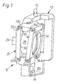
- FIG. 1 An independent wheel suspension 10 for a motor vehicle is partially shown schematically in FIG. 1 .
- the frame-shaped wheel carrier 12 is connected via indicated ball joints 14, 16 to wheel guide elements such as wishbones etc. (not shown).
- the wheel suspension 10 shown is designed for a steered wheel 18 (cf. FIGS. 2 to 4 ), the wheel 18 being composed in a known manner of a rim and an air-filled tire.
- the wheel suspension 10 can also be designed for an unguided rear wheel of a motor vehicle.
- the wheel 18 is by means of a corresponding connection flange having shaft 26 via wheel bearings, not shown, in a wheel hub 28 rotatably mounted, between the rim and the connecting flange in a known manner, a brake disc 30 not Disc brake of the motor vehicle shown with a hydraulic actuated brake application element (not visible) is arranged.
- the brake application member is attached to the wheel hub 28.
- the wheel hub 28 is with the wheel carrier 12 via two frame-shaped Coupling 32, 34 articulated, each with a central Recess 36 around the wheel hub 28 and substantially perpendicular are arranged.
- Each coupling 32, 34 is oriented approximately horizontally Swivel axes or two bearing points 32b, 34b on the Wheel carrier 12 and also via two bearings 32a, 34a on the Wheel hub 28 articulated, for this purpose to the wheel hub 28 and to the Corresponding bearing brackets 28a and 12a are integrally formed.
- the bearings 32a, 34a and 32b, 34b can in wheel suspensions usually by so-called rubber-metal sleeve bearings or be formed silent blocs or plain or roller bearings.
- the wheel hub 28 can thus be moved relative to the wheel carrier 12 in a manner similar to a parallel guide, an instantaneous pole MP being set on the basis of the apparent position, the lengths and the predetermined angles of the coupling 32, 34 and the camber 40 (see FIGS. 2 to 4 ), which lies below the wheel contact area (line 38) of the tire of the wheel 18 on the roadway of the motor vehicle.
- the instantaneous pole MP results from the imaginary extension of the bearing points 32a, 32b or 34a, 34b of the coupling 32, 34 and lies in the vertical center of the wheel of the wheel 18.
- couplers 32, 34 are also so that a self-stabilizing system is achieved, in which each depending on the size of the lateral force (arrow 42) and the wheel contact force (Arrow 44) a defined camber 40 that the Deformation of the tire of the wheel 18 counteracts in the tire contact patch.
- FIGS. 2 to 4 This is shown in FIGS. 2 to 4 on the basis of the lateral forces shown by arrow 42. Due to the instantaneous pole MP lying below the point of application (wheel contact line 38) and in the vertical center of the wheel, the camber 40 is changed by means of the pivotable coupling 32, 34 in such a way that it counteracts the deformation of the tire flap. In fact, the camber 40 changes from an assumed neutral position ( FIG. 3 ) with a lateral force from the left ( FIG. 2 ) into a positive camber 40 and with a lateral force from the right into a negative camber 40 ( FIG. 4 ).
- the drawing of FIGS. 2 to 4 is based on the assumption that the wheel 18 is positioned on the outside of the curve in the case of FIG. 2 and on the inside of the motor vehicle in the case of FIG. 4 .
- the neutral position of the wheel 18 shown in FIG. 3 can be predetermined in a manner not shown by resilient means, for example by rubber buffers switched into the swivel range of the couplers 32, 34, which exert a defined prestress on the couplers 32, 34.
- resilient means for example by rubber buffers switched into the swivel range of the couplers 32, 34, which exert a defined prestress on the couplers 32, 34.
- hydraulic damping means for example a telescopic shock absorber, can be provided, which suppress the formation of any vibrations that may occur on the coupling 32, 34 or on the wheel hub 28.
Landscapes
- Engineering & Computer Science (AREA)
- Mechanical Engineering (AREA)
- Vehicle Body Suspensions (AREA)
- Arrangement Or Mounting Of Propulsion Units For Vehicles (AREA)
Abstract
Description
Die Erfindung betrifft eine Radaufhängung, insbesondere für Kraftfahrzeuge,
gemäß dem Oberbegriff des Patentanspruches 1.The invention relates to a wheel suspension, in particular for motor vehicles,
according to the preamble of
Für die exakte Radführung und das Fahrverhalten und den Fahrkomfort eines Fahrzeuges, insbesondere von Kraftfahrzeugen, ist der Reifen ein wesentlicher Parameter der Radaufhängung. Insbesondere bei schnellfahrenden Kraftfahrzeugen werden vermehrt Niederquerschnitt-Reifen eingesetzt, die u.a. eine verbesserte Kurvenstabilität durch höhere Seitensteifigkeit aufweisen. Damit kann aber unter Berücksichtigung eines zufriedenstellenden Dämpfungsverhalten des Reifens nicht vermieden werden, dass sich der Reifen unter dem Seitenkrafteinfluss z.B. beim Durchfahren von Kurven verformt, wodurch sich eine verringerte, etwa trapezförmige Radaufstandsfläche einstellt und zudem der Reifen im Reifenlatsch eine ungleichmäßige Druckverteilung erfährt. Die erreichbaren Seitenkräfte bzw. Kurvengeschwindigkeiten des Fahrzeuges liegen unterhalb der physikalisch möglichen Leistungsgrenze des Reifens.For exact wheel guidance and driving behavior and driving comfort a vehicle, in particular motor vehicles, is the tire an essential parameter of the wheel suspension. Especially at high-speed motor vehicles are increasingly low-profile tires used, among other things improved cornering stability through higher Have lateral stiffness. But this can be considered a satisfactory damping behavior of the tire avoid that the tire is under the influence of lateral forces e.g. deformed when cornering, which reduces sets about trapezoidal wheel contact patch and also the Tires in the tire patch experience an uneven pressure distribution. The achievable lateral forces or cornering speeds of the vehicle are below the physically possible performance limit of the tire.
Aufgabe der Erfindung ist es, eine Radaufhängung der gattungsgemäßen Art vorzuschlagen, mit der die Reifenverformung bei auftretenden Seitenkräften verringerbar und damit ohne negative Beeinflussung des Fahrkomforts eine höhere Kurvenstabilität des Fahrzeuges erzielbar ist. The object of the invention is a wheel suspension of the generic type To propose the way in which the tire deformation when occurring Lateral forces can be reduced and thus without negatively influencing the Driving comfort a higher cornering stability of the vehicle can be achieved.
Diese Aufgabe wird erfindungsgemäß mit den kennzeichnenden Merkmalen
des Patentanspruches 1 gelöst. Vorteilhafte Weiterbildungen der
Erfindung sind in den weiteren Patentansprüchen angeführt.This object is achieved with the characterizing features
of
Erfindungsgemäß wird vorgeschlagen, dass die Radnabe der Radaufhängung über Führungsmittel nachgiebig mit dem Radträger verbunden ist, wobei der Momentanpol der den Radsturz bei Seitenkrafteinwirkung verändernden Führungsmittel unterhalb der Radaufstandsfläche des Reifens auf der Fahrbahn liegt. Daraus resultiert, dass sich das Rad abhängig von der auftretenden Seitenkraft z.B. beim Durchfahren von Kurven über die Führungsmittel durch entsprechende Radsturzänderung in die Kurve hinein neigen kann und dadurch der Verformung des Reifenlatsches entgegen wirkt. Die Reifenaufstandsfläche ist unverändert etwa rechteckförmig und es liegt eine gleichmäßigere Druckverteilung im Reifenlatsch vor, die die Aufnahme bzw. Übertragung höherer Seitenkräfte in Kurven ermöglicht.According to the invention it is proposed that the wheel hub of the wheel suspension flexibly connected to the wheel carrier via guide means is, the instantaneous pole of the camber when subjected to lateral forces changing guide means below the wheel contact area of the Tire is on the road. As a result, the wheel depending on the lateral force, e.g. when driving through Curves over the guide means by changing the camber accordingly can tilt into the curve and thereby the deformation of the Counteracts tire flats. The tire contact area is unchanged roughly rectangular and there is a more even pressure distribution in the tire patch before that the recording or transmission higher Lateral forces in curves allowed.
Die besagten Führungsmittel können eine entsprechend ausgebildete Kulissenführung zwischen der Radnabe und dem Radträger oder entsprechend angeordnete Gummilager sein, die die gezielte Nachgiebigkeit ergeben. Bevorzugt wird jedoch vorgeschlagen, dass die Führungsmittel zumindest zwei im wesentlichen senkrecht verlaufende Koppeln mit etwa horizontal ausgerichteten Schwenkachsen sind, die einenends mit dem Radträger und anderenends mit der Radnabe schwenkbar verbunden sind und deren gedachte Verlängerungen den Momentanpol definieren. Die Verwendung entsprechender Koppeln ergibt größere Freiheitsgrade bei der Auslegung der Führungsmittel und deren Anordnung an der Radaufhängung. Des weiteren ist eine exaktere Radsturzbeeinflussung über die auftretenden Seitenkräfte möglich. The said guide means can be appropriately designed Link guide between the wheel hub and the wheel carrier or accordingly arranged rubber bearings, which the targeted compliance result. However, it is preferably proposed that the guide means at least two substantially vertical ones Coupling with approximately horizontally aligned swivel axes are the one end with the wheel carrier and the other end with the wheel hub are pivotally connected and their imaginary extensions Define the current pole. The use of appropriate coupling gives greater degrees of freedom in the design of the guide means and their arrangement on the wheel suspension. Furthermore is one more precise wheel camber influence via the lateral forces that occur possible.
In vorteilhafter Weiterbildung der Erfindung wird vorgeschlagen, die Position, die Längen und den Winkel der Koppeln bzw. den Momentanpol zur auftretenden Radlast so zu definieren, dass sich abhängig von der momentanen Seitenkraft eine definierte Radsturzstellung einstellt. Dies heißt, dass sich das vorgeschlagene System selbststabilisierend verhält und sich jeweils abhängig von der Radlast als dem einen Parameter und der Seitenkraft als dem weiteren Parameter so einstellt, dass der Radsturz einer optimalen Seitenkraftübertragung entspricht.In an advantageous development of the invention, it is proposed that Position, length and angle of the coupling or the current pole To define the occurring wheel load so that it depends sets a defined camber position from the current lateral force. This means that the proposed system is self-stabilizing behaves and depends on the wheel load as the one Parameters and the lateral force as the further parameter so that the camber corresponds to an optimal lateral force transmission.
Die Koppeln können baulich besonders vorteilhaft über jeweils zwei die horizontalen Schwenkachsen bildende Lagerstellen mit dem Radträger und der Radnabe verbunden und über zentrale Ausnehmungen um die Radnabe herum angeordnet sein. Dies ermöglicht eine an gegebene Einbauverhältnisse günstig anpassbare und besonders kompakte Konstruktion, bei der die Führungsmittel unmittelbar um die Radnabe herum positionierbar sind.The coupling can be structurally particularly advantageous over two each horizontal pivot points with the wheel carrier and the wheel hub connected and via central recesses around the Wheel hub can be arranged around. This enables a given Installation conditions, inexpensively adaptable and particularly compact construction, in which the guide means directly around the wheel hub can be positioned around.
Ferner wird vorgeschlagen, bei einem Kraftfahrzeug mit Scheibenbremsen das Bremszuspannorgan an der Radnabe und nicht wie üblich an dem Radträger zu befestigen, so dass das Bremszuspannorgan mit der Radnabe und der an dem Rad bzw. dessen Achse oder Welle angeordneten Bremsscheibe eine über die Führungsmittel nachgiebige Funktionseinheit bilden kann.It is also proposed in a motor vehicle with disc brakes the brake application element on the wheel hub and not as usual to attach to the wheel carrier so that the brake application element with the wheel hub and that arranged on the wheel or its axle or shaft Brake disc compliant with the guide means Functional unit can form.
Des weiteren können im Kraftfluss zwischen der Radnabe und dem Radträger federnde Mittel vorgesehen sein, die in gezielter Weise die Radsturzänderungen in vorteilhafter Weise mit beeinflussen können.Furthermore, in the power flow between the wheel hub and the Resilient means are provided, which in a targeted manner the Can influence wheel camber changes in an advantageous manner.
Insbesondere können die federnden Mittel jedoch die Radnabe in eine konstruktiv vorgegebene Position vorspannen, die beispielsweise einer Grundstellung (Neutralstellung) des Rades bei Geradeausfahrt des Kraftfahrzeuges, also ohne Seitenkrafteinfluss, entspricht.In particular, the resilient means, however, the wheel hub in one preload predetermined position, for example one Home position (neutral position) of the wheel when driving the Motor vehicle, that is, without the influence of lateral forces.
Dabei können die federnden Mittel bevorzugt gummielastische Puffer sein, die zudem eine definierte Dämpfungswirkung auf die Führungsmittel und die Radnabe ausüben können.The resilient means can preferably be rubber-elastic buffers be, which also has a defined damping effect on the guide means and can exercise the wheel hub.
Dies schließt aber nicht aus, dass nicht ggf. zusätzliche Dämpfungsmittel wie z.B. ein hydraulischer Stoßdämpfer vorteilhaft einsetzbar sind, um im Fahrbetrieb ggf. auftretenden hochfrequenten Schwingungen entgegen zu wirken. Die dämpfenden Mittel können dabei bevorzugt unmittelbar auf die Koppeln bzw. Führungsmittel wirken.However, this does not exclude that additional damping agents may not be required such as. a hydraulic shock absorber can be used advantageously are to avoid high-frequency vibrations that may occur during driving to counteract. The damping agents can be preferred act directly on the paddocks or guide means.
Ein Ausführungsbeispiel der Erfindung ist im Folgenden mit weiteren Einzelheiten näher beschrieben.An embodiment of the invention is below with others Details described in more detail.
Die anliegende schematische Zeichnung zeigt in:
- Fig. 1
- in raumbildlicher Darstellung eine Radaufhängung für ein Kraftfahrzeug mit Führungsmitteln zum Seitenkraft abhängigen Verändern des Radsturzes mittels zwischen der Radnabe und dem Radträger angeordneten Koppeln;
- Fig. 2
- in schematischer Darstellung die Radsturzänderung der Radaufhängung gemäß Fig. 1 bei einer Seitenkraft von links;
- Fig. 3
- den Radsturz der Radaufhängung gemäß Fig. 1 ohne Seitenkraft in einer Neutralstellung; und
- Fig. 4
- die Radsturzänderung der Radaufhängung gemäß Fig. 1 bei einer entgegengerichteten Seitenkraft von rechts.
- Fig. 1
- in a spatial representation a wheel suspension for a motor vehicle with guide means for lateral force-dependent changing of the camber by means of coupling arranged between the wheel hub and the wheel carrier;
- Fig. 2
- in a schematic representation, the camber change of the wheel suspension according to Figure 1 with a lateral force from the left.
- Fig. 3
- the camber of the wheel suspension according to Figure 1 without lateral force in a neutral position. and
- Fig. 4
- the camber change of the wheel suspension according to FIG. 1 with an opposing lateral force from the right.
In der Fig. 1 ist schematisch eine unabhängige Radaufhängung 10 für
ein Kraftfahrzeug teilweise dargestellt. Dabei ist der rahmenförmige,
Radträger 12 über angedeutete Kugelgelenke 14, 16 mit Radführungselementen
wie Querlenkern etc. (nicht dargestellt) verbunden. Die dargestellte
Radaufhängung 10 ist für ein gelenktes Rad 18 (vgl. Fig. 2 bis
4) ausgelegt, wobei das Rad 18 sich in bekannter Weise aus einer Felge
und einem luftgefüllten Reifen zusammen setzt. Die Radaufhängung
10 kann aber auch für ein ungelenktes Hinterrad eines Kraftfahrzeuges
ausgeführt sein.An
Das Rad 18 ist mittels einer einen entsprechenden Anschlussflansch
aufweisenden Welle 26 über nicht dargestellte Radlager in einer Radnabe
28 drehbar gelagert, wobei zwischen der Felge und dem Anschlussflansch
in bekannter Weise eine Bremsscheibe 30 einer nicht
dargestellten Scheibenbremse des Kraftfahrzeuges mit einem hydraulisch
betätigten Bremszuspannorgan (nicht ersichtlich) angeordnet ist.
Das Bremszuspannorgan ist an der Radnabe 28 befestigt.The
Die Radnabe 28 ist mit dem Radträger 12 über zwei rahmenförmige
Koppeln 32, 34 gelenkig verbunden, die mit jeweils einer zentralen
Ausnehmung 36 um die Radnabe 28 herum und im wesentlichen senkrecht
angeordnet sind.The
Dabei ist eine jede Koppel 32, 34 um etwa horizontal ausgerichtete
Schwenkachsen bzw. jeweils über zwei Lagerstellen 32b, 34b an dem
Radträger 12 und über ebenfalls zwei Lagerstellen 32a, 34a an der
Radnabe 28 angelenkt, wobei dazu an die Radnabe 28 und an den
Radträger entsprechende Lagerkonsolen 28a bzw. 12a angeformt sind.
Die Lagerstellen 32a, 34a bzw. 32b, 34b können in bei Radaufhängungen
üblicher Weise durch sogenannte Gummi-Metall-Hülsenlager bzw.
silent blocs bzw. Gleit- oder Rollenlager gebildet sein.Each
Die Radnabe 28 ist somit ähnlich einer Parallelführung relativ zum
Radträger 12 beweglich, wobei aufgrund der ersichtlichen Position, der
Längen und der vorgegebenen Winkel der Koppeln 32, 34 und zum
Radsturz 40 (vgl. Fig. 2 bis 4) ein Momentanpol MP eingestellt ist, der
unterhalb der Radaufstandsfläche (Linie 38) des Reifens des Rades 18
auf der Fahrbahn des Kraftfahrzeuges liegt. Der Momentanpol MP ergibt
sich aus der gedachten Verlängerung der Lagerstellen 32a, 32b
bzw. 34a, 34b der Koppeln 32, 34 und liegt in der senkrechten Radmitte
des Rades 18.The
Die Auslegung und Anordnung der besagten Koppeln 32, 34 ist zudem
so, dass ein selbststabilisierendes System erreicht ist, bei dem sich jeweils
abhängig von der Größe der Seitenkraft (Pfeil 42) und der Radaufstandskraft
(Pfeil 44) ein definierter Radsturz 40 einstellt, der der
Verformung des Reifens des Rades 18 im Reifenlatsch entgegenwirkt.The design and arrangement of said
Dies zeigen die Fig. 2 bis 4 anhand der mit dem Pfeil 42 eingezeichneten
Seitenkräfte. Durch den unterhalb des Angriffspunktes (Radaufstandslinie
38) und in der senkrechten Radmitte liegenden Momentanpol
MP wird der Radsturz 40 mittels der schwenkbaren Koppeln 32, 34
so verändert, dass er der Verformung-des Reifenlatsches entgegenwirkt.
Faktisch ändert sich der Radsturz 40 ausgehend von einer angenommenen
Neutralstellung (Fig. 3) bei einer Seitenkraft von links (Fig.
2) in einen positiven Radsturz 40 und bei einer Seitenkraft von rechts in
einen negativen Radsturz 40 (Fig. 4). Der Zeichnung Fig. 2 bis 4 liegt
dabei die Annahme zugrunde, dass das Rad 18 im Fall der Fig. 2 kurvenaußen
und im Fall der Fig. 4 kurveninnen des Kraftfahrzeuges positioniert
ist.This is shown in FIGS. 2 to 4 on the basis of the lateral forces shown by
Die in der Fig. 3 dargestellte Neutralstellung des Rades 18 kann in
nicht dargestellter Weise durch federnde Mittel vorgegeben sein, beispielsweise
durch in den Schwenkbereich der Koppeln 32, 34 eingeschaltete
Gummipuffer, die eine definierte Vorspannung auf die Koppeln
32, 34 ausüben. Ferner können hydraulische Dämpfungsmittel,
z.B. ein Teleskop-Stoßdämpfer, vorgesehen sein, die die Ausbildung
ggf. auftretender Schwingungen an den Koppeln 32, 34 bzw. an der
Radnabe 28 unterdrücken.The neutral position of the
Claims (10)
Applications Claiming Priority (2)
| Application Number | Priority Date | Filing Date | Title |
|---|---|---|---|
| DE10247663 | 2002-10-11 | ||
| DE2002147663 DE10247663A1 (en) | 2002-10-11 | 2002-10-11 | Wheel suspension, in particular for motor vehicles |
Publications (2)
| Publication Number | Publication Date |
|---|---|
| EP1407902A1 true EP1407902A1 (en) | 2004-04-14 |
| EP1407902B1 EP1407902B1 (en) | 2010-01-27 |
Family
ID=32010466
Family Applications (1)
| Application Number | Title | Priority Date | Filing Date |
|---|---|---|---|
| EP20030021289 Expired - Lifetime EP1407902B1 (en) | 2002-10-11 | 2003-09-19 | Wheel suspension, particularly for motor vehicles |
Country Status (2)
| Country | Link |
|---|---|
| EP (1) | EP1407902B1 (en) |
| DE (2) | DE10247663A1 (en) |
Cited By (3)
| Publication number | Priority date | Publication date | Assignee | Title |
|---|---|---|---|---|
| FR2884795A1 (en) * | 2005-04-26 | 2006-10-27 | Michelin Soc Tech | SUSPENSION DEVICE WITH VARIABLE BODY |
| WO2008071153A1 (en) * | 2006-12-15 | 2008-06-19 | Zf Friedrichshafen Ag | Wheel suspension |
| WO2008074292A1 (en) * | 2006-12-21 | 2008-06-26 | Zf Friedrichshafen Ag | Wheel suspension |
Families Citing this family (3)
| Publication number | Priority date | Publication date | Assignee | Title |
|---|---|---|---|---|
| JP4844026B2 (en) * | 2005-07-12 | 2011-12-21 | 日産自動車株式会社 | Vehicle suspension system |
| DE102009057577B4 (en) * | 2009-12-09 | 2020-01-16 | Continental Automotive Gmbh | Position determination for individual tires of a multiple tire |
| US20220250430A1 (en) * | 2021-02-11 | 2022-08-11 | GM Global Technology Operations LLC | Multilink mid-height suspension assembly for motor vehicles |
Citations (4)
| Publication number | Priority date | Publication date | Assignee | Title |
|---|---|---|---|---|
| EP0462399A1 (en) | 1990-06-21 | 1991-12-27 | Dr.Ing.h.c. F. Porsche Aktiengesellschaft | Wheel suspension |
| WO1992012868A1 (en) | 1991-01-26 | 1992-08-06 | Zahnradfabrik Friedrichshafen Ag | Wheel suspension |
| WO1992016387A1 (en) * | 1991-03-14 | 1992-10-01 | Josef Nusser | Vehicle with travelling mechanism |
| FR2806693A1 (en) | 2000-03-27 | 2001-09-28 | Michelin & Cie | Vehicle wheel support and suspension system has suspension rods giving wheel a degree of camber freedom |
Family Cites Families (5)
| Publication number | Priority date | Publication date | Assignee | Title |
|---|---|---|---|---|
| AT408207B (en) * | 1998-08-10 | 2001-09-25 | Ehrenleitner Franz | WHEEL SWIVEL SYSTEM |
| JP2003528771A (en) * | 2000-03-27 | 2003-09-30 | ソシエテ ド テクノロジー ミシュラン | Wheel support device and suspension device provided with support device |
| DE10041200B4 (en) * | 2000-08-23 | 2005-10-06 | Zf Sachs Ag | Suspension strut with fall compensation |
| JP4460831B2 (en) * | 2001-01-23 | 2010-05-12 | ソシエテ ド テクノロジー ミシュラン | Vehicle wheel suspension system |
| EP1275534A1 (en) * | 2001-07-10 | 2003-01-15 | Société de Technologie Michelin | Motor vehicle suspension with a variable camber |
-
2002
- 2002-10-11 DE DE2002147663 patent/DE10247663A1/en not_active Withdrawn
-
2003
- 2003-09-19 DE DE50312376T patent/DE50312376D1/en not_active Expired - Lifetime
- 2003-09-19 EP EP20030021289 patent/EP1407902B1/en not_active Expired - Lifetime
Patent Citations (4)
| Publication number | Priority date | Publication date | Assignee | Title |
|---|---|---|---|---|
| EP0462399A1 (en) | 1990-06-21 | 1991-12-27 | Dr.Ing.h.c. F. Porsche Aktiengesellschaft | Wheel suspension |
| WO1992012868A1 (en) | 1991-01-26 | 1992-08-06 | Zahnradfabrik Friedrichshafen Ag | Wheel suspension |
| WO1992016387A1 (en) * | 1991-03-14 | 1992-10-01 | Josef Nusser | Vehicle with travelling mechanism |
| FR2806693A1 (en) | 2000-03-27 | 2001-09-28 | Michelin & Cie | Vehicle wheel support and suspension system has suspension rods giving wheel a degree of camber freedom |
Cited By (3)
| Publication number | Priority date | Publication date | Assignee | Title |
|---|---|---|---|---|
| FR2884795A1 (en) * | 2005-04-26 | 2006-10-27 | Michelin Soc Tech | SUSPENSION DEVICE WITH VARIABLE BODY |
| WO2008071153A1 (en) * | 2006-12-15 | 2008-06-19 | Zf Friedrichshafen Ag | Wheel suspension |
| WO2008074292A1 (en) * | 2006-12-21 | 2008-06-26 | Zf Friedrichshafen Ag | Wheel suspension |
Also Published As
| Publication number | Publication date |
|---|---|
| EP1407902B1 (en) | 2010-01-27 |
| DE10247663A1 (en) | 2004-04-22 |
| DE50312376D1 (en) | 2010-03-18 |
Similar Documents
| Publication | Publication Date | Title |
|---|---|---|
| DE102004043891B4 (en) | wheel assembly | |
| DE102010061008B4 (en) | Active geometry control suspension system and actuator for driving the same | |
| DE102012200001A1 (en) | Rubber-metal bearing for trapezoidal-link in wheel suspension, has rubber elastic body fastened and arranged between outer bush and inner bush, where outer bush has front end surface at which leading elastic damping element is mounted | |
| EP2497660B1 (en) | Motor vehicle axle with virtual steering axle | |
| DE102013210338A1 (en) | Multi-link rear axle for a vehicle | |
| WO2007087797A1 (en) | Wheel suspension for a motor vehicle | |
| EP2712796A2 (en) | Wheel suspension for an inclining vehicle | |
| EP1592570A1 (en) | Wheel suspension for motor vehicles | |
| EP2239155A1 (en) | Axle construction for a vehicle, in particular a commercial vehicle | |
| EP3153737B1 (en) | Suspension bearing | |
| EP1407902A1 (en) | Wheel suspension, particularly for motor vehicles | |
| DE102018201435A1 (en) | Axle | |
| EP1231083B1 (en) | Axle suspension for rigid axles in commercial vehicles | |
| EP1577126B1 (en) | Elastomeric mounting | |
| WO2024052479A1 (en) | Axle structure for a commercial vehicle chassis having an axle bridge | |
| EP4335668A1 (en) | Axle construction for a commercial vehicle chassis with an axle bridge designed as a cast part | |
| DE102012221841B4 (en) | Rubber-metal bearings for automotive suspension, trapezoidal link and suspension | |
| DE102022123034A1 (en) | Axle construction for a commercial vehicle chassis with an axle bridge | |
| DE102023130038B3 (en) | Bearing device for axle, control arm and drive and motor vehicle | |
| DE102015203567A1 (en) | Independent and rear suspension with independent wheel suspensions for one vehicle | |
| DE202015101117U1 (en) | Independent and rear suspension with independent wheel suspensions for one vehicle | |
| DE102020202056B4 (en) | Wheel suspension | |
| DE19507397C2 (en) | Twist link or coupling link axle for motor vehicles | |
| DE102018207586A1 (en) | Axle | |
| DE202004004168U1 (en) | Roll stabilizer for two-track vehicle axle has first and second stabilizer arm each having pivot point which during compression and rebound of wheel executes circular motion with effective radius around respective joint of wishbone |
Legal Events
| Date | Code | Title | Description |
|---|---|---|---|
| PUAI | Public reference made under article 153(3) epc to a published international application that has entered the european phase |
Free format text: ORIGINAL CODE: 0009012 |
|
| AK | Designated contracting states |
Kind code of ref document: A1 Designated state(s): AT BE BG CH CY CZ DE DK EE ES FI FR GB GR HU IE IT LI LU MC NL PT RO SE SI SK TR |
|
| AX | Request for extension of the european patent |
Extension state: AL LT LV MK |
|
| 17P | Request for examination filed |
Effective date: 20040220 |
|
| AKX | Designation fees paid |
Designated state(s): DE FR GB IT |
|
| 17Q | First examination report despatched |
Effective date: 20080408 |
|
| GRAP | Despatch of communication of intention to grant a patent |
Free format text: ORIGINAL CODE: EPIDOSNIGR1 |
|
| GRAS | Grant fee paid |
Free format text: ORIGINAL CODE: EPIDOSNIGR3 |
|
| GRAA | (expected) grant |
Free format text: ORIGINAL CODE: 0009210 |
|
| AK | Designated contracting states |
Kind code of ref document: B1 Designated state(s): DE FR GB IT |
|
| REG | Reference to a national code |
Ref country code: GB Ref legal event code: FG4D Free format text: NOT ENGLISH |
|
| REF | Corresponds to: |
Ref document number: 50312376 Country of ref document: DE Date of ref document: 20100318 Kind code of ref document: P |
|
| PLBE | No opposition filed within time limit |
Free format text: ORIGINAL CODE: 0009261 |
|
| STAA | Information on the status of an ep patent application or granted ep patent |
Free format text: STATUS: NO OPPOSITION FILED WITHIN TIME LIMIT |
|
| 26N | No opposition filed |
Effective date: 20101028 |
|
| REG | Reference to a national code |
Ref country code: DE Ref legal event code: R084 Ref document number: 50312376 Country of ref document: DE |
|
| REG | Reference to a national code |
Ref country code: DE Ref legal event code: R084 Ref document number: 50312376 Country of ref document: DE Effective date: 20110715 |
|
| PGFP | Annual fee paid to national office [announced via postgrant information from national office to epo] |
Ref country code: GB Payment date: 20140922 Year of fee payment: 12 |
|
| PGFP | Annual fee paid to national office [announced via postgrant information from national office to epo] |
Ref country code: FR Payment date: 20140922 Year of fee payment: 12 |
|
| GBPC | Gb: european patent ceased through non-payment of renewal fee |
Effective date: 20150919 |
|
| REG | Reference to a national code |
Ref country code: FR Ref legal event code: ST Effective date: 20160531 |
|
| PG25 | Lapsed in a contracting state [announced via postgrant information from national office to epo] |
Ref country code: GB Free format text: LAPSE BECAUSE OF NON-PAYMENT OF DUE FEES Effective date: 20150919 |
|
| PG25 | Lapsed in a contracting state [announced via postgrant information from national office to epo] |
Ref country code: FR Free format text: LAPSE BECAUSE OF NON-PAYMENT OF DUE FEES Effective date: 20150930 |
|
| PGFP | Annual fee paid to national office [announced via postgrant information from national office to epo] |
Ref country code: DE Payment date: 20160930 Year of fee payment: 14 |
|
| PGFP | Annual fee paid to national office [announced via postgrant information from national office to epo] |
Ref country code: IT Payment date: 20160930 Year of fee payment: 14 |
|
| REG | Reference to a national code |
Ref country code: DE Ref legal event code: R119 Ref document number: 50312376 Country of ref document: DE |
|
| PG25 | Lapsed in a contracting state [announced via postgrant information from national office to epo] |
Ref country code: DE Free format text: LAPSE BECAUSE OF NON-PAYMENT OF DUE FEES Effective date: 20180404 |
|
| PG25 | Lapsed in a contracting state [announced via postgrant information from national office to epo] |
Ref country code: IT Free format text: LAPSE BECAUSE OF NON-PAYMENT OF DUE FEES Effective date: 20170919 |