EP1407902A1 - Suspension de roue, notamment pour véhicules automobiles - Google Patents
Suspension de roue, notamment pour véhicules automobiles Download PDFInfo
- Publication number
- EP1407902A1 EP1407902A1 EP03021289A EP03021289A EP1407902A1 EP 1407902 A1 EP1407902 A1 EP 1407902A1 EP 03021289 A EP03021289 A EP 03021289A EP 03021289 A EP03021289 A EP 03021289A EP 1407902 A1 EP1407902 A1 EP 1407902A1
- Authority
- EP
- European Patent Office
- Prior art keywords
- wheel
- suspension according
- wheel hub
- wheel suspension
- hub
- Prior art date
- Legal status (The legal status is an assumption and is not a legal conclusion. Google has not performed a legal analysis and makes no representation as to the accuracy of the status listed.)
- Granted
Links
Images

Classifications
-
- B—PERFORMING OPERATIONS; TRANSPORTING
- B60—VEHICLES IN GENERAL
- B60G—VEHICLE SUSPENSION ARRANGEMENTS
- B60G7/00—Pivoted suspension arms; Accessories thereof
- B60G7/008—Attaching arms to unsprung part of vehicle
-
- B—PERFORMING OPERATIONS; TRANSPORTING
- B60—VEHICLES IN GENERAL
- B60G—VEHICLE SUSPENSION ARRANGEMENTS
- B60G21/00—Interconnection systems for two or more resiliently-suspended wheels, e.g. for stabilising a vehicle body with respect to acceleration, deceleration or centrifugal forces
- B60G21/007—Interconnection systems for two or more resiliently-suspended wheels, e.g. for stabilising a vehicle body with respect to acceleration, deceleration or centrifugal forces means for adjusting the wheel inclination
-
- B—PERFORMING OPERATIONS; TRANSPORTING
- B60—VEHICLES IN GENERAL
- B60G—VEHICLE SUSPENSION ARRANGEMENTS
- B60G3/00—Resilient suspensions for a single wheel
- B60G3/18—Resilient suspensions for a single wheel with two or more pivoted arms, e.g. parallelogram
- B60G3/20—Resilient suspensions for a single wheel with two or more pivoted arms, e.g. parallelogram all arms being rigid
-
- B—PERFORMING OPERATIONS; TRANSPORTING
- B60—VEHICLES IN GENERAL
- B60G—VEHICLE SUSPENSION ARRANGEMENTS
- B60G2200/00—Indexing codes relating to suspension types
- B60G2200/10—Independent suspensions
- B60G2200/14—Independent suspensions with lateral arms
- B60G2200/144—Independent suspensions with lateral arms with two lateral arms forming a parallelogram
- B60G2200/1442—Independent suspensions with lateral arms with two lateral arms forming a parallelogram including longitudinal rods
-
- B—PERFORMING OPERATIONS; TRANSPORTING
- B60—VEHICLES IN GENERAL
- B60G—VEHICLE SUSPENSION ARRANGEMENTS
- B60G2200/00—Indexing codes relating to suspension types
- B60G2200/10—Independent suspensions
- B60G2200/18—Multilink suspensions, e.g. elastokinematic arrangements
-
- B—PERFORMING OPERATIONS; TRANSPORTING
- B60—VEHICLES IN GENERAL
- B60G—VEHICLE SUSPENSION ARRANGEMENTS
- B60G2200/00—Indexing codes relating to suspension types
- B60G2200/40—Indexing codes relating to the wheels in the suspensions
- B60G2200/44—Indexing codes relating to the wheels in the suspensions steerable
-
- B—PERFORMING OPERATIONS; TRANSPORTING
- B60—VEHICLES IN GENERAL
- B60G—VEHICLE SUSPENSION ARRANGEMENTS
- B60G2200/00—Indexing codes relating to suspension types
- B60G2200/40—Indexing codes relating to the wheels in the suspensions
- B60G2200/46—Indexing codes relating to the wheels in the suspensions camber angle
-
- B—PERFORMING OPERATIONS; TRANSPORTING
- B60—VEHICLES IN GENERAL
- B60G—VEHICLE SUSPENSION ARRANGEMENTS
- B60G2202/00—Indexing codes relating to the type of spring, damper or actuator
- B60G2202/10—Type of spring
- B60G2202/14—Plastic spring, e.g. rubber
- B60G2202/142—Plastic spring, e.g. rubber subjected to shear, e.g. Neidhart type
- B60G2202/1424—Torsional
-
- B—PERFORMING OPERATIONS; TRANSPORTING
- B60—VEHICLES IN GENERAL
- B60G—VEHICLE SUSPENSION ARRANGEMENTS
- B60G2202/00—Indexing codes relating to the type of spring, damper or actuator
- B60G2202/10—Type of spring
- B60G2202/14—Plastic spring, e.g. rubber
- B60G2202/144—Plastic spring, e.g. rubber of rotary type
-
- B—PERFORMING OPERATIONS; TRANSPORTING
- B60—VEHICLES IN GENERAL
- B60G—VEHICLE SUSPENSION ARRANGEMENTS
- B60G2204/00—Indexing codes related to suspensions per se or to auxiliary parts
- B60G2204/10—Mounting of suspension elements
- B60G2204/14—Mounting of suspension arms
- B60G2204/148—Mounting of suspension arms on the unsprung part of the vehicle, e.g. wheel knuckle or rigid axle
-
- B—PERFORMING OPERATIONS; TRANSPORTING
- B60—VEHICLES IN GENERAL
- B60G—VEHICLE SUSPENSION ARRANGEMENTS
- B60G2204/00—Indexing codes related to suspensions per se or to auxiliary parts
- B60G2204/40—Auxiliary suspension parts; Adjustment of suspensions
- B60G2204/422—Links for mounting suspension elements
-
- B—PERFORMING OPERATIONS; TRANSPORTING
- B60—VEHICLES IN GENERAL
- B60G—VEHICLE SUSPENSION ARRANGEMENTS
- B60G2204/00—Indexing codes related to suspensions per se or to auxiliary parts
- B60G2204/40—Auxiliary suspension parts; Adjustment of suspensions
- B60G2204/44—Centering or positioning means
-
- B—PERFORMING OPERATIONS; TRANSPORTING
- B60—VEHICLES IN GENERAL
- B60G—VEHICLE SUSPENSION ARRANGEMENTS
- B60G2204/00—Indexing codes related to suspensions per se or to auxiliary parts
- B60G2204/40—Auxiliary suspension parts; Adjustment of suspensions
- B60G2204/45—Stops limiting travel
- B60G2204/4502—Stops limiting travel using resilient buffer
-
- B—PERFORMING OPERATIONS; TRANSPORTING
- B60—VEHICLES IN GENERAL
- B60G—VEHICLE SUSPENSION ARRANGEMENTS
- B60G2206/00—Indexing codes related to the manufacturing of suspensions: constructional features, the materials used, procedures or tools
- B60G2206/01—Constructional features of suspension elements, e.g. arms, dampers, springs
- B60G2206/50—Constructional features of wheel supports or knuckles, e.g. steering knuckles, spindle attachments
Definitions
- the invention relates to a wheel suspension, in particular for motor vehicles, according to the preamble of claim 1.
- a vehicle in particular motor vehicles, is the tire an essential parameter of the wheel suspension.
- This can be considered a satisfactory damping behavior of the tire avoid that the tire is under the influence of lateral forces e.g. deformed when cornering, which reduces sets about trapezoidal wheel contact patch and also the Tires in the tire patch experience an uneven pressure distribution.
- the achievable lateral forces or cornering speeds of the vehicle are below the physically possible performance limit of the tire.
- the object of the invention is a wheel suspension of the generic type To propose the way in which the tire deformation when occurring Lateral forces can be reduced and thus without negatively influencing the Driving comfort a higher cornering stability of the vehicle can be achieved.
- the wheel hub of the wheel suspension flexibly connected to the wheel carrier via guide means is, the instantaneous pole of the camber when subjected to lateral forces changing guide means below the wheel contact area of the Tire is on the road.
- the wheel depending on the lateral force e.g. when driving through Curves over the guide means by changing the camber accordingly can tilt into the curve and thereby the deformation of the Counteracts tire flats.
- the tire contact area is unchanged roughly rectangular and there is a more even pressure distribution in the tire patch before that the recording or transmission higher Lateral forces in curves allowed.
- the said guide means can be appropriately designed Link guide between the wheel hub and the wheel carrier or accordingly arranged rubber bearings, which the targeted compliance result.
- the guide means at least two substantially vertical ones Coupling with approximately horizontally aligned swivel axes are the one end with the wheel carrier and the other end with the wheel hub are pivotally connected and their imaginary extensions Define the current pole.
- the use of appropriate coupling gives greater degrees of freedom in the design of the guide means and their arrangement on the wheel suspension. Furthermore is one more precise wheel camber influence via the lateral forces that occur possible.
- the coupling can be structurally particularly advantageous over two each horizontal pivot points with the wheel carrier and the wheel hub connected and via central recesses around the Wheel hub can be arranged around. This enables a given Installation conditions, inexpensively adaptable and particularly compact construction, in which the guide means directly around the wheel hub can be positioned around.
- the resilient means however, the wheel hub in one preload predetermined position, for example one Home position (neutral position) of the wheel when driving the Motor vehicle, that is, without the influence of lateral forces.
- the resilient means can preferably be rubber-elastic buffers be, which also has a defined damping effect on the guide means and can exercise the wheel hub.
- damping agents may not be required such as.
- a hydraulic shock absorber can be used advantageously are to avoid high-frequency vibrations that may occur during driving to counteract.
- the damping agents can be preferred act directly on the paddocks or guide means.
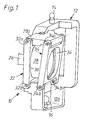
- FIG. 1 An independent wheel suspension 10 for a motor vehicle is partially shown schematically in FIG. 1 .
- the frame-shaped wheel carrier 12 is connected via indicated ball joints 14, 16 to wheel guide elements such as wishbones etc. (not shown).
- the wheel suspension 10 shown is designed for a steered wheel 18 (cf. FIGS. 2 to 4 ), the wheel 18 being composed in a known manner of a rim and an air-filled tire.
- the wheel suspension 10 can also be designed for an unguided rear wheel of a motor vehicle.
- the wheel 18 is by means of a corresponding connection flange having shaft 26 via wheel bearings, not shown, in a wheel hub 28 rotatably mounted, between the rim and the connecting flange in a known manner, a brake disc 30 not Disc brake of the motor vehicle shown with a hydraulic actuated brake application element (not visible) is arranged.
- the brake application member is attached to the wheel hub 28.
- the wheel hub 28 is with the wheel carrier 12 via two frame-shaped Coupling 32, 34 articulated, each with a central Recess 36 around the wheel hub 28 and substantially perpendicular are arranged.
- Each coupling 32, 34 is oriented approximately horizontally Swivel axes or two bearing points 32b, 34b on the Wheel carrier 12 and also via two bearings 32a, 34a on the Wheel hub 28 articulated, for this purpose to the wheel hub 28 and to the Corresponding bearing brackets 28a and 12a are integrally formed.
- the bearings 32a, 34a and 32b, 34b can in wheel suspensions usually by so-called rubber-metal sleeve bearings or be formed silent blocs or plain or roller bearings.
- the wheel hub 28 can thus be moved relative to the wheel carrier 12 in a manner similar to a parallel guide, an instantaneous pole MP being set on the basis of the apparent position, the lengths and the predetermined angles of the coupling 32, 34 and the camber 40 (see FIGS. 2 to 4 ), which lies below the wheel contact area (line 38) of the tire of the wheel 18 on the roadway of the motor vehicle.
- the instantaneous pole MP results from the imaginary extension of the bearing points 32a, 32b or 34a, 34b of the coupling 32, 34 and lies in the vertical center of the wheel of the wheel 18.
- couplers 32, 34 are also so that a self-stabilizing system is achieved, in which each depending on the size of the lateral force (arrow 42) and the wheel contact force (Arrow 44) a defined camber 40 that the Deformation of the tire of the wheel 18 counteracts in the tire contact patch.
- FIGS. 2 to 4 This is shown in FIGS. 2 to 4 on the basis of the lateral forces shown by arrow 42. Due to the instantaneous pole MP lying below the point of application (wheel contact line 38) and in the vertical center of the wheel, the camber 40 is changed by means of the pivotable coupling 32, 34 in such a way that it counteracts the deformation of the tire flap. In fact, the camber 40 changes from an assumed neutral position ( FIG. 3 ) with a lateral force from the left ( FIG. 2 ) into a positive camber 40 and with a lateral force from the right into a negative camber 40 ( FIG. 4 ).
- the drawing of FIGS. 2 to 4 is based on the assumption that the wheel 18 is positioned on the outside of the curve in the case of FIG. 2 and on the inside of the motor vehicle in the case of FIG. 4 .
- the neutral position of the wheel 18 shown in FIG. 3 can be predetermined in a manner not shown by resilient means, for example by rubber buffers switched into the swivel range of the couplers 32, 34, which exert a defined prestress on the couplers 32, 34.
- resilient means for example by rubber buffers switched into the swivel range of the couplers 32, 34, which exert a defined prestress on the couplers 32, 34.
- hydraulic damping means for example a telescopic shock absorber, can be provided, which suppress the formation of any vibrations that may occur on the coupling 32, 34 or on the wheel hub 28.
Landscapes
- Engineering & Computer Science (AREA)
- Mechanical Engineering (AREA)
- Vehicle Body Suspensions (AREA)
- Arrangement Or Mounting Of Propulsion Units For Vehicles (AREA)
Applications Claiming Priority (2)
| Application Number | Priority Date | Filing Date | Title |
|---|---|---|---|
| DE10247663 | 2002-10-11 | ||
| DE2002147663 DE10247663A1 (de) | 2002-10-11 | 2002-10-11 | Radaufhängung, insbesondere für Kraftfahrzeuge |
Publications (2)
| Publication Number | Publication Date |
|---|---|
| EP1407902A1 true EP1407902A1 (fr) | 2004-04-14 |
| EP1407902B1 EP1407902B1 (fr) | 2010-01-27 |
Family
ID=32010466
Family Applications (1)
| Application Number | Title | Priority Date | Filing Date |
|---|---|---|---|
| EP20030021289 Expired - Lifetime EP1407902B1 (fr) | 2002-10-11 | 2003-09-19 | Suspension de roue, notamment pour véhicules automobiles |
Country Status (2)
| Country | Link |
|---|---|
| EP (1) | EP1407902B1 (fr) |
| DE (2) | DE10247663A1 (fr) |
Cited By (3)
| Publication number | Priority date | Publication date | Assignee | Title |
|---|---|---|---|---|
| FR2884795A1 (fr) * | 2005-04-26 | 2006-10-27 | Michelin Soc Tech | Dispositif de suspension a carrossage variable |
| WO2008071153A1 (fr) * | 2006-12-15 | 2008-06-19 | Zf Friedrichshafen Ag | Suspension de roue |
| WO2008074292A1 (fr) * | 2006-12-21 | 2008-06-26 | Zf Friedrichshafen Ag | Suspension de roue |
Families Citing this family (3)
| Publication number | Priority date | Publication date | Assignee | Title |
|---|---|---|---|---|
| JP4844026B2 (ja) * | 2005-07-12 | 2011-12-21 | 日産自動車株式会社 | 車両用サスペンション装置 |
| DE102009057577B4 (de) * | 2009-12-09 | 2020-01-16 | Continental Automotive Gmbh | Positionsbestimmung für einzelne Reifen eines Mehrfachreifens |
| US20220250430A1 (en) * | 2021-02-11 | 2022-08-11 | GM Global Technology Operations LLC | Multilink mid-height suspension assembly for motor vehicles |
Citations (4)
| Publication number | Priority date | Publication date | Assignee | Title |
|---|---|---|---|---|
| EP0462399A1 (fr) | 1990-06-21 | 1991-12-27 | Dr.Ing.h.c. F. Porsche Aktiengesellschaft | Suspension de roue |
| WO1992012868A1 (fr) | 1991-01-26 | 1992-08-06 | Zahnradfabrik Friedrichshafen Ag | Suspension |
| WO1992016387A1 (fr) * | 1991-03-14 | 1992-10-01 | Josef Nusser | Vehicule avec mecanisme de roulement |
| FR2806693A1 (fr) | 2000-03-27 | 2001-09-28 | Michelin & Cie | Dispositif de support d'une roue de vehicule |
Family Cites Families (5)
| Publication number | Priority date | Publication date | Assignee | Title |
|---|---|---|---|---|
| AT408207B (de) * | 1998-08-10 | 2001-09-25 | Ehrenleitner Franz | Radschwenksystem |
| JP2003528771A (ja) * | 2000-03-27 | 2003-09-30 | ソシエテ ド テクノロジー ミシュラン | 車輪支持装置および支持装置を備えたサスペンション装置 |
| DE10041200B4 (de) * | 2000-08-23 | 2005-10-06 | Zf Sachs Ag | Federbein mit Sturzausgleich |
| JP4460831B2 (ja) * | 2001-01-23 | 2010-05-12 | ソシエテ ド テクノロジー ミシュラン | 車両ホイールのサスペンションシステム |
| EP1275534A1 (fr) * | 2001-07-10 | 2003-01-15 | Société de Technologie Michelin | Suspension à carrossage variable pour véhicule automobile |
-
2002
- 2002-10-11 DE DE2002147663 patent/DE10247663A1/de not_active Withdrawn
-
2003
- 2003-09-19 DE DE50312376T patent/DE50312376D1/de not_active Expired - Lifetime
- 2003-09-19 EP EP20030021289 patent/EP1407902B1/fr not_active Expired - Lifetime
Patent Citations (4)
| Publication number | Priority date | Publication date | Assignee | Title |
|---|---|---|---|---|
| EP0462399A1 (fr) | 1990-06-21 | 1991-12-27 | Dr.Ing.h.c. F. Porsche Aktiengesellschaft | Suspension de roue |
| WO1992012868A1 (fr) | 1991-01-26 | 1992-08-06 | Zahnradfabrik Friedrichshafen Ag | Suspension |
| WO1992016387A1 (fr) * | 1991-03-14 | 1992-10-01 | Josef Nusser | Vehicule avec mecanisme de roulement |
| FR2806693A1 (fr) | 2000-03-27 | 2001-09-28 | Michelin & Cie | Dispositif de support d'une roue de vehicule |
Cited By (3)
| Publication number | Priority date | Publication date | Assignee | Title |
|---|---|---|---|---|
| FR2884795A1 (fr) * | 2005-04-26 | 2006-10-27 | Michelin Soc Tech | Dispositif de suspension a carrossage variable |
| WO2008071153A1 (fr) * | 2006-12-15 | 2008-06-19 | Zf Friedrichshafen Ag | Suspension de roue |
| WO2008074292A1 (fr) * | 2006-12-21 | 2008-06-26 | Zf Friedrichshafen Ag | Suspension de roue |
Also Published As
| Publication number | Publication date |
|---|---|
| EP1407902B1 (fr) | 2010-01-27 |
| DE10247663A1 (de) | 2004-04-22 |
| DE50312376D1 (de) | 2010-03-18 |
Similar Documents
| Publication | Publication Date | Title |
|---|---|---|
| DE102004043891B4 (de) | Radaufbau | |
| DE102010061008B4 (de) | Aktive-Geometrie-Steuerung-Aufhängungssystem und Betätigungsvorrichtung zum Antreiben derselben | |
| DE102012200001A1 (de) | Gummimetallager für Kraftfahrzeug-Radaufhängung, Trapezlenker und Radaufhängung | |
| EP2497660B1 (fr) | Axe de véhicule automobile doté d'un axe de direction virtuel | |
| DE102013210338A1 (de) | Mehrlenkerhinterachse für ein Fahrzeug | |
| WO2007087797A1 (fr) | Suspension de roue pour vehicule automobile | |
| EP2712796A2 (fr) | Suspension de roue pour véhicule inclinable | |
| EP1592570A1 (fr) | Suspension de roue destinee a des vehicules | |
| EP2239155A1 (fr) | Structure d'essieu pour un véhicule, notamment pour un véhicule utilitaire | |
| EP3153737B1 (fr) | Palier de châssis | |
| EP1407902A1 (fr) | Suspension de roue, notamment pour véhicules automobiles | |
| DE102018201435A1 (de) | Achsaufhängung | |
| EP1231083B1 (fr) | Suspension d'essieu pour essieux rigides de véhicules utilitaires | |
| EP1577126B1 (fr) | Support en élastomère | |
| WO2024052479A1 (fr) | Structure d'essieu d'un châssis de véhicule utilitaire comportant un pont d'essieu | |
| EP4335668A1 (fr) | Structure d'essieu pour un châssis de véhicule utilitaire doté d'un pont d'essieu conçu comme pièce moulée | |
| DE102012221841B4 (de) | Gummimetalllager für Kraftfahrzeug-Radaufhängung, Trapezlenker und Radaufhängung | |
| DE102022123034A1 (de) | Achskonstruktion für ein Nutzfahrzeug-Fahrwerk mit einer Achsbrücke | |
| DE102023130038B3 (de) | Lagervorrichtung für Achse, Lenker und Antrieb und Kraftfahrzeug | |
| DE102015203567A1 (de) | Einzelradaufhängung sowie Hinterachse mit Einzelradaufhängungen für ein Fahrzeug | |
| DE202015101117U1 (de) | Einzelradaufhängung sowie Hinterachse mit Einzelradaufhängungen für ein Fahrzeug | |
| DE102020202056B4 (de) | Radaufhängung | |
| DE19507397C2 (de) | Verbundlenker- oder Koppellenkerachse für Kraftfahrzeuge | |
| DE102018207586A1 (de) | Achsaufhängung | |
| DE202004004168U1 (de) | Wankstabilisator |
Legal Events
| Date | Code | Title | Description |
|---|---|---|---|
| PUAI | Public reference made under article 153(3) epc to a published international application that has entered the european phase |
Free format text: ORIGINAL CODE: 0009012 |
|
| AK | Designated contracting states |
Kind code of ref document: A1 Designated state(s): AT BE BG CH CY CZ DE DK EE ES FI FR GB GR HU IE IT LI LU MC NL PT RO SE SI SK TR |
|
| AX | Request for extension of the european patent |
Extension state: AL LT LV MK |
|
| 17P | Request for examination filed |
Effective date: 20040220 |
|
| AKX | Designation fees paid |
Designated state(s): DE FR GB IT |
|
| 17Q | First examination report despatched |
Effective date: 20080408 |
|
| GRAP | Despatch of communication of intention to grant a patent |
Free format text: ORIGINAL CODE: EPIDOSNIGR1 |
|
| GRAS | Grant fee paid |
Free format text: ORIGINAL CODE: EPIDOSNIGR3 |
|
| GRAA | (expected) grant |
Free format text: ORIGINAL CODE: 0009210 |
|
| AK | Designated contracting states |
Kind code of ref document: B1 Designated state(s): DE FR GB IT |
|
| REG | Reference to a national code |
Ref country code: GB Ref legal event code: FG4D Free format text: NOT ENGLISH |
|
| REF | Corresponds to: |
Ref document number: 50312376 Country of ref document: DE Date of ref document: 20100318 Kind code of ref document: P |
|
| PLBE | No opposition filed within time limit |
Free format text: ORIGINAL CODE: 0009261 |
|
| STAA | Information on the status of an ep patent application or granted ep patent |
Free format text: STATUS: NO OPPOSITION FILED WITHIN TIME LIMIT |
|
| 26N | No opposition filed |
Effective date: 20101028 |
|
| REG | Reference to a national code |
Ref country code: DE Ref legal event code: R084 Ref document number: 50312376 Country of ref document: DE |
|
| REG | Reference to a national code |
Ref country code: DE Ref legal event code: R084 Ref document number: 50312376 Country of ref document: DE Effective date: 20110715 |
|
| PGFP | Annual fee paid to national office [announced via postgrant information from national office to epo] |
Ref country code: GB Payment date: 20140922 Year of fee payment: 12 |
|
| PGFP | Annual fee paid to national office [announced via postgrant information from national office to epo] |
Ref country code: FR Payment date: 20140922 Year of fee payment: 12 |
|
| GBPC | Gb: european patent ceased through non-payment of renewal fee |
Effective date: 20150919 |
|
| REG | Reference to a national code |
Ref country code: FR Ref legal event code: ST Effective date: 20160531 |
|
| PG25 | Lapsed in a contracting state [announced via postgrant information from national office to epo] |
Ref country code: GB Free format text: LAPSE BECAUSE OF NON-PAYMENT OF DUE FEES Effective date: 20150919 |
|
| PG25 | Lapsed in a contracting state [announced via postgrant information from national office to epo] |
Ref country code: FR Free format text: LAPSE BECAUSE OF NON-PAYMENT OF DUE FEES Effective date: 20150930 |
|
| PGFP | Annual fee paid to national office [announced via postgrant information from national office to epo] |
Ref country code: DE Payment date: 20160930 Year of fee payment: 14 |
|
| PGFP | Annual fee paid to national office [announced via postgrant information from national office to epo] |
Ref country code: IT Payment date: 20160930 Year of fee payment: 14 |
|
| REG | Reference to a national code |
Ref country code: DE Ref legal event code: R119 Ref document number: 50312376 Country of ref document: DE |
|
| PG25 | Lapsed in a contracting state [announced via postgrant information from national office to epo] |
Ref country code: DE Free format text: LAPSE BECAUSE OF NON-PAYMENT OF DUE FEES Effective date: 20180404 |
|
| PG25 | Lapsed in a contracting state [announced via postgrant information from national office to epo] |
Ref country code: IT Free format text: LAPSE BECAUSE OF NON-PAYMENT OF DUE FEES Effective date: 20170919 |