EP1407127B1 - Verbundgasturbine und verfahren zu ihrem betrieb - Google Patents
Verbundgasturbine und verfahren zu ihrem betrieb Download PDFInfo
- Publication number
- EP1407127B1 EP1407127B1 EP02745559A EP02745559A EP1407127B1 EP 1407127 B1 EP1407127 B1 EP 1407127B1 EP 02745559 A EP02745559 A EP 02745559A EP 02745559 A EP02745559 A EP 02745559A EP 1407127 B1 EP1407127 B1 EP 1407127B1
- Authority
- EP
- European Patent Office
- Prior art keywords
- combustion chamber
- combustion
- engine
- valve
- turbine
- Prior art date
- Legal status (The legal status is an assumption and is not a legal conclusion. Google has not performed a legal analysis and makes no representation as to the accuracy of the status listed.)
- Expired - Lifetime
Links
- 238000000034 method Methods 0.000 title claims description 17
- 150000001875 compounds Chemical class 0.000 title description 3
- 238000002485 combustion reaction Methods 0.000 claims abstract description 194
- 239000000446 fuel Substances 0.000 claims abstract description 47
- 238000013329 compounding Methods 0.000 claims abstract description 18
- 230000002269 spontaneous effect Effects 0.000 claims abstract description 5
- 238000012546 transfer Methods 0.000 claims description 47
- 238000002347 injection Methods 0.000 claims description 27
- 239000007924 injection Substances 0.000 claims description 27
- 238000001816 cooling Methods 0.000 claims description 14
- 230000002000 scavenging effect Effects 0.000 claims description 6
- 230000000694 effects Effects 0.000 claims description 3
- 230000001419 dependent effect Effects 0.000 claims 1
- 239000007789 gas Substances 0.000 description 12
- 230000007246 mechanism Effects 0.000 description 9
- 230000007704 transition Effects 0.000 description 8
- 238000010587 phase diagram Methods 0.000 description 3
- 238000013517 stratification Methods 0.000 description 3
- 230000006835 compression Effects 0.000 description 2
- 238000007906 compression Methods 0.000 description 2
- 238000011161 development Methods 0.000 description 2
- 230000018109 developmental process Effects 0.000 description 2
- 239000002283 diesel fuel Substances 0.000 description 2
- 239000007788 liquid Substances 0.000 description 2
- 230000001360 synchronised effect Effects 0.000 description 2
- OKTJSMMVPCPJKN-UHFFFAOYSA-N Carbon Chemical compound [C] OKTJSMMVPCPJKN-UHFFFAOYSA-N 0.000 description 1
- 238000013459 approach Methods 0.000 description 1
- 230000008901 benefit Effects 0.000 description 1
- 229910052799 carbon Inorganic materials 0.000 description 1
- 239000000567 combustion gas Substances 0.000 description 1
- 230000001010 compromised effect Effects 0.000 description 1
- 238000010276 construction Methods 0.000 description 1
- 238000013461 design Methods 0.000 description 1
- 238000005474 detonation Methods 0.000 description 1
- 238000010586 diagram Methods 0.000 description 1
- 238000001125 extrusion Methods 0.000 description 1
- 230000008642 heat stress Effects 0.000 description 1
- 238000010438 heat treatment Methods 0.000 description 1
- 238000009434 installation Methods 0.000 description 1
- 239000010687 lubricating oil Substances 0.000 description 1
- 238000005461 lubrication Methods 0.000 description 1
- 239000000203 mixture Substances 0.000 description 1
- 238000012986 modification Methods 0.000 description 1
- 230000004048 modification Effects 0.000 description 1
- 230000000750 progressive effect Effects 0.000 description 1
- 230000002035 prolonged effect Effects 0.000 description 1
- 238000007789 sealing Methods 0.000 description 1
- 230000011218 segmentation Effects 0.000 description 1
- 230000002459 sustained effect Effects 0.000 description 1
Images


Classifications
-
- F—MECHANICAL ENGINEERING; LIGHTING; HEATING; WEAPONS; BLASTING
- F02—COMBUSTION ENGINES; HOT-GAS OR COMBUSTION-PRODUCT ENGINE PLANTS
- F02C—GAS-TURBINE PLANTS; AIR INTAKES FOR JET-PROPULSION PLANTS; CONTROLLING FUEL SUPPLY IN AIR-BREATHING JET-PROPULSION PLANTS
- F02C5/00—Gas-turbine plants characterised by the working fluid being generated by intermittent combustion
- F02C5/12—Gas-turbine plants characterised by the working fluid being generated by intermittent combustion the combustion chambers having inlet or outlet valves, e.g. Holzwarth gas-turbine plants
-
- F—MECHANICAL ENGINEERING; LIGHTING; HEATING; WEAPONS; BLASTING
- F02—COMBUSTION ENGINES; HOT-GAS OR COMBUSTION-PRODUCT ENGINE PLANTS
- F02C—GAS-TURBINE PLANTS; AIR INTAKES FOR JET-PROPULSION PLANTS; CONTROLLING FUEL SUPPLY IN AIR-BREATHING JET-PROPULSION PLANTS
- F02C5/00—Gas-turbine plants characterised by the working fluid being generated by intermittent combustion
- F02C5/02—Gas-turbine plants characterised by the working fluid being generated by intermittent combustion characterised by the arrangement of the combustion chamber in the chamber in the plant
Definitions
- This invention relates to engines and to methods of operation thereof.
- the invention is applicable to engines of the type having a compressor for compressing air, a plurality of combustion chambers each having at least one fuel injector and in which fuel mixed with the compressed air combusts, and a turbine which is driven by the products of combustion.
- Such an arrangement forms the basis of a conventional gas turbine engine.
- Such engines are typically used to produce mechanical power via a power take-off and/or to produce thrust, and the turbine is typically used to drive the compressor.
- the thermal efficiency of a conventional gas turbine engine is relatively poor when compared with that of a turbo-charged diesel engine or, more particularly, a compound diesel engine.
- the reason for the lower thermal efficiency of the gas turbine engine is primarily due to the comparatively low temperature and pressure at which combustion takes place, and these parameters are limited by the pressure ratio of the compressor.
- the present invention is concerned with improving the performance of the gas turbine engine by enabling the temperature and pressure at which combustion takes place to be increased substantially.
- each combustion chamber operates in a cycle comprising the phases of: charging the combustion chamber with a charge of compressed air from the compressor while preventing air from escaping from the combustion chamber; then compounding by charging with a compounding charge of gas to form a compounded charge; then commencing injection of fuel into the combustion chamber so that there is spontaneous ignition and combustion of the fuel with the compounded charge at generally constant pressure; and then exhausting the products of combustion to the turbine.
- the cycles of the combustion chambers are out of phase in a sequence, and part of the compounded charge (and/or the products of combustion thereof) in each combustion chamber during the combustion phase thereof is transferred before the exhaust phase thereof to the next combustion chamber in the sequence to provide the compounding charge for that next combustion chamber. It will be appreciated that this transfer of a compounding charge from one combustion chamber to the next increases the temperature and pressure by compression of the air in the latter combustion chamber. The ensuing combustion in the latter combustion chamber therefore takes place at an elevated temperature and pressure, thus improving the thermal efficiency of the engine and/or enabling lower grade and/or higher flashpoint fuel to be used.
- Patent document GB-A-892143 describes a method of operation of a combustion gas generator that has some similarities to the present invention.
- the charging phase acts solely as a scavenging phase so that the pressure in the combustion chamber at the end of the charging/scavenging phase is somewhere between the compressor outlet pressure and either the turbine back-pressure or atmospheric pressure and is thus comparatively low so that the overall efficiency of the engine is thereby compromised.
- the method of GB-A-892143 relies on spark-ignition of the air/fuel mixture and is therefore prone to excessively high peak temperatures and pressures before the exhaust phase commences.
- the method of the present invention employs spontaneous ignition, whereby the ensuing combustion can readily be controlled to provide progressive and prolonged fuel burning at generally constant pressure.
- patent document DE-C-383286 discloses a somewhat similar method.
- the cycle of each combustion chamber also includes a phase, between its exhaust phase and its charging phase, of permitting scavenge/cooling air to flow through the combustion chamber from the compressor to the turbine.
- This serves to scavenge the combustion chamber and also to cool the combustion chamber, any exhaust valves, and the turbine.
- the duration of the charging phase is such that the pressure of the fresh air charge in the combustion chamber is increased and preferably maximised by a "ram" effect.
- each combustion chamber is elongate, ie has a length substantially greater than its diameter or its cross-sectional dimensions.
- the charging with air takes place at or adjacent one end of each combustion chamber, and the exhausting of the products of combustion takes place at or adjacent the opposite end of each combustion chamber. This serves to encourage stratification along the combustion chamber.
- the combustion phase for each combustion chamber includes injecting fuel into that combustion chamber.
- the transfer of the compounding charge takes place at or adjacent one end of each combustion chamber, and the injection of fuel takes place at or adjacent the other end of each combustion chamber. Accordingly, there is a tendency for the compounding charge to be air, rather than products of combustion.
- each combustion chamber is connected to the compressor via a respective inlet port having a respective inlet valve; each combustion chamber is connected to the turbine via a respective exhaust port having a respective exhaust valve; the combustion chambers are arranged as at least one series and in the, or each, series are operable sequentially; each combustion chamber is connected to the next combustion chamber in the, or the respective, series via a respective transfer port having a respective transfer valve; and the engine further comprises means for operating the valves and injectors so that the engine operates according to the method of the first aspect of the invention.
- valve and injector operating means is operable so that, during the charging phase for each combustion chamber, the inlet valve for that chamber is open and the exhaust valve for that chamber is closed, so as to provide the ram effect mentioned above.
- valve and injector operating means is operable to provide a scavenge/cooling phase for each combustion chamber, in which the inlet valve and the exhaust valve for that chamber are both open.
- each inlet valve, exhaust valve and/or transfer valve preferably comprises a respective poppet valve, piston-operated valve, rotary valve or sleeve valve.
- the compressor and the turbine preferably each have housings that are fixed relative to the combustion chambers. Designed to contain high combustion pressures, these chambers can therefore form an integral part of the overall engine structure.
- the rotating drum of combustion chambers is driven by the turbine shaft so that the porting operates at turbine speed. Accordingly, each sector of turbine blading may always experience the same part of the working cycle, so that some sectors of the turbine blading may be hotter than others. This may lead to difficulties with differential heating, carbon build-up and so on.
- the valve and injector operating means is preferably mechanically driven by the turbine via at least one gearbox. Accordingly, it can be arranged that the turbine blading precesses relative to the engine cycle.
- the compressor is mechanically driven by the turbine via at least one gearbox. This may be particularly advantageous in the case of a centrifugal compressor and an axial turbine.
- each inlet port is disposed at or adjacent one end of the respective combustion chamber, and each exhaust port is disposed at or adjacent the opposite end of the respective combustion chamber.
- the engine preferably further includes, for each combustion chamber, at least one respective fuel injector.
- each transfer port is disposed at or adjacent one end of the respective combustion chambers, and each fuel injector is disposed at or adjacent the opposite end of the respective combustion chamber.
- Each inlet valve, exhaust valve and/or transfer valve preferably comprises a respective poppet valve, piston-operated valve, rotary valve or sleeve valve.
- the engine further includes a nozzle ring between the exhaust ports and the turbine, the nozzle ring having a plurality of segments each corresponding to a respective one of the combustion chambers.
- segmentation reduces interference between neighbouring turbine inlet nozzle segments and adjacent combustion chambers due to fluctuating pressures.
- a gas turbine engine 10 has a compressor 12, combustion stage 14 and turbine 16.
- the compressor 12 and turbine 16 may be of generally conventional design/construction, and each may be a multi-stage unit.
- the turbine 16 is typically connected to and drives the compressor 12 through shaft 18.
- a second co-axial shaft 19 is provided for the operation and synchronisation of the auxiliary equipment, including the valves, the fuel injection system, the governor and the lubrication system.
- Shaft 18 and the co-axial shaft 19 are preferably connected by means of gearing or, in the case of stationary applications, the co-axial shaft 19 may be driven by external means, in which case, the governor must be driven by the shaft 18 in order to control the output speed.
- the engine 10 may have a mechanical power take-off, for instance in stationary or marine applications, or it may be used as a turboprop engine or as a turbojet or in any other configuration of thrust producing engine.
- the novelty of the engine 10 lies primarily in the method of compounding in the combustion stage 14.
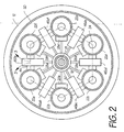
- the combustion stage 14 has an enclosure 20, which houses a circular array of six elongate combustion chambers 22a-f, or pressure vessels, with their longitudinal axes generally parallel to and arranged around the shafts 18 and 19.
- each combustion chamber 22a-f is connected via a respective inlet port 24 to a manifold 26 at the outlet of the compressor 12.
- Each inlet port 24 contains a respective inlet valve 28a-f which is operated by an inlet and transfer valve actuator mechanism 30 which may in turn be driven by the co-axial shaft 19.
- Each inlet valve 28a-f may be a poppet valve which is forced open by the actuator mechanism 30, preferably by means of a cam and which is closed by a spring and which is assisted in remaining closed by the pressure in the respective combustion chamber 22a-f.
- other types of inlet valve may be employed including piston, rotary or sleeve operated valves.
- each combustion chamber 22a-f is connected via a respective exhaust port 32 to a respective segment 34a-f of a nozzle ring 36 at the inlet to the turbine 16.
- Each exhaust port contains a respective exhaust valve 38a-f which is operated by an exhaust valve mechanism 40 which may in turn be driven by the co-axial shaft 19.
- Each exhaust valve 38a-f may be a piston operated valve which is operated by the actuator mechanism 40, preferably by means of an eccentric or short stroke crank.
- other types of exhaust valve may be employed including poppet valves, rotary or sleeve operated valves.
- a respective fuel injection nozzle 42a-f Adjacent the exhaust end of each combustion chamber 22a-f, a respective fuel injection nozzle 42a-f is provided.
- the fuel injection nozzles are operated sequentially to inject diesel fuel into the respective combustion chambers 22a-f and their timing is controlled by a fuel injection pump 43 driven by (and shown diagrammatically adjacent to) co-axial shaft 19. More than one fuel injection nozzle 42a-f may be provided to serve each combustion chamber 22a-f.
- the fuel injection pump 43 may be an in-line fuel pump fitted with an integral governor, or a rotary distribution fuel pump, again with an integral governor.
- each chamber 22a-f may be supplied with fuel using individual combined fuel pump/injector/nozzle units which in turn may be actuated by co-axial shaft 19, although such an arrangement would require a separate linked governor unit driven by shaft 18 in order to control the output speed.
- each combustion chamber Adjacent the inlet end of each combustion chamber (e.g. chamber 22b), the combustion chamber is connected to the two adjacent combustion chambers (e.g. chambers 22a,22c) by respective transfer ports 44.
- Each transfer port 44 contains a respective transfer valve 46ab,46bc,46cd,46de,46ef,46fa which is operated by the inlet and transfer valve actuator mechanism 30.
- Each transfer valve 46ab,46bc,46cd,46de,46ef 46fa may be a piston valve which is operated by the actuator mechanism 30, preferably by means of an eccentric or short stroke crank. Alternatively, other types of transfer valve may be employed, including rotary or sleeve operated valves.
- the inlet and transfer valve actuator mechanism 30 has been considered above and shown schematically as a single unit operated by the co-axial shaft 19, but in practice separate units or mechanisms may be provided for actuating the inlet valves 28a-f and for actuating the transfer valves 46ab,46bc,46cd,46de,46ef,46fa.
- the co-axial shaft 19 may either be driven through gearing by the shaft 18 or alternatively driven by external means, it is foreseen that provision would also be made for small variations in the respective valve timings and/or the respective fuel injection timings to meet different operating conditions, whilst still maintaining overall synchronisation of the auxiliary functions. It is also foreseen that the gear ratio between shaft 18 and the auxiliary co-axial drive shaft 19 must be chosen such that the sequence of functions taking place in the combustion chambers will be out of synchronisation with, or multiples of, turbine rotational speed. This will ensure, for example, that the exhaust pulses will be constantly precessing in relation to the rotation, or multiples of revolutions, of the turbine blading, irrespective of the relative speeds or directions of shaft rotation, with a view to minimizing differential heat stresses.
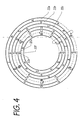
- phase 4 The relative lengths of the phases A to E are shown in Figure 4 as: A - 90°; B - 60°; C - 60°; D - 60°; and E - 90°. Nevertheless, the relative phases of A, D and E may vary considerably from those shown in Figure 4 although the compounding phase B and the combustion/transfer stage C are equal and limited to a maximum of 60° for the six combustion chamber configuration.
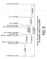
- FIG. 5 is a more detailed cycle diagram for any one of the combustion chambers 22. Again it shows that the compounding phase B and the combustion/transfer phase C are equal and limited to 60°. Fuel injection is shown diagrammatically to commence with the start of transfer and the rate of fuel injection is intended to maintain approximately constant pressure throughout the combustion and transfer phase. Normally, fuel injection will be completed before the end of the transfer phase, leaving sufficient tolerance for the governor to maintain the required speed/power output to match the engine load. It will be appreciated, however, that the configuration lends itself to a wide range of predetermined rates of fuel injection and timing such that under certain operating conditions injection may commence marginally before the start of transfer or it may end marginally after the end of transfer.
- each combustion chamber 22a-f is elongate, ie its length between its inlet ports 24 and its exhaust ports 32 is substantially greater than its diameter or cross-sectional dimensions. Furthermore, the fuel injectors 42a-f and the transfer ports 44 are located at opposite ends of each combustion chamber in order to provide optimum stratification between charge air and the residual products of combustion. When fuel is injected during the combustion phase C, combustion will tend to be concentrated at the same end as the injection nozzle whereas the charge air will be concentrated at the transfer port end of the chamber. Therefore, the air/gas which is transferred to the next combustion chamber in the sequence will have a high concentration of unburned air.
- the transfer ports are located adjacent the inlet ports and the injection nozzles are located adjacent the exhaust ports.
- stratification can also be achieved if the injection nozzles are adjacent the inlet valves and the transfer ports are adjacent the exhaust valves. This is the subject of an alternative double cycle or duplex engine described later with reference to Figures 6 to 9.
- the engine 10 described above is preferably used at near constant speed and/or with near constant power output. It requires additional equipment for starting, such as a means of cranking it up to operating speed and may require the introduction or injection of a volatile fuel with synchronised spark ignition, until the compression ignition cycle can be sustained.
- the enclosure 20 may serve to collect used lubricating oil, for example on a dry sump basis, and to carry additional cooling air bled from the compressor and exhausted into a late turbine stage. This bleed air may be used for additional external cooling for the combustion chambers and, particularly for the transfer ports and their respective valves.
- the enclosure 20 may also be used to contain and vent any gas leaks which may occur, for example at the inlet poppet valve stems or past the piston rings of the transfer and exhaust valves.
- the external surfaces of the combustion chambers 22a-f may be provided with radial, longitudinal or spiral finning to assist in cooling and/or the combustion chambers 22a-f may be provided with liquid cooling. In the case where longitudinal finning is employed, the combustion chambers may be formed by extrusion.
- the ideal application for this engine would be for electrical generation, particularly standby generation and for marine propulsion and the associated marine auxiliary engines, in each case using a geared mechanical power take-off.
- the engine may also be developed for aircraft propulsion, in turboprop, turbojet and other configurations, where the improved efficiency can be shown to offset any increase in weight and where the engine would provide improved safety by using high flashpoint, low grade diesel fuels.
- combustion chambers 22a-f have been shown merely by way of example, and other numbers of combustion chambers may be provided.
- the auxiliary functions including the valves and fuel injection equipment may be operated by the co-axial gear driven shaft 19 or, in stationary installations, the co-axial shaft 19 may be driven by external means such as an electric motor so that the speed of operation of the valves and injection equipment can be controlled more easily independently of the speed of the gas turbine shaft 18.
- the speed of such a motor may be controlled so as to provide precession between the working cycles of the combustion chambers and the turbine.
- the governor must be linked to the shaft 18 in order to control the output speed.
- the absolute and/or the relative timing of the auxiliaries may be varied, for example by providing automatic or manually-operable advance/retard mechanisms or systems, to fine tune the engine performance in respect of variations in load/speed.
- the combustion chambers are operated in a single cycle, and it will be appreciated that this produces an unbalanced axial load on the turbine.
- the combustion chambers may be operated in a double cycle where an engine has say ten combustion chambers such that diametrically opposite chambers are synchronized by using double lobe cams to actuate opposing valves, instead of eccentrics or short stroke cranks. Accordingly, it will be appreciated that, at any time when one of the combustion chambers is in its exhaust phase, the diametrically opposite combustion chamber will also be in its exhaust phase such that the axial loads on the turbine are balanced.
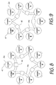
- the effective combustion and transfer phases are being shortened with the increase in number of chambers, in this case being limited to a maximum of 36°, so an alternative layout is proposed below and this is shown in Figures 6 to 9.
- Figures 6 to 9 show that a balanced arrangement can be achieved by providing say ten combustion chambers in a double series of five interposed chambers.
- alternate chambers are linked for transfer and this configuration allows a maximum of 72° for each combustion/transfer phase and also allows the use of eccentrics or short stroke cranks for the control of the transfer and exhaust valves.
- Odd numbered chambers 22o are connected to each other by transfer ports 44o and even numbered chambers 22e are connected by transfer ports 44e.
- the valve and injection timing is arranged such that diametrically opposite chambers are always performing the same operation and thereby preserve the axial balance.
- Other features of the engine of Figures 6 to 9 are referenced with the same reference numerals as those used above in relation to Figures 1 to 5.
- the shaft 18 may provide a direct drive between the turbine and the compressor, whilst gearing between concentric shafts 18,19 ensures that the engine combustion cycles precess in relation to the turbine rotation.
- gearing may be included at each end of the shaft 19, in which case there is no need for the shaft 18.
- Such an arrangement is preferred to allow for the pre-selection of optimum speed ratios between the compressor, the auxiliaries and the turbine. It also permits the use of short stroke cranks along the shaft 19 for the operation of the piston valves via connecting rods.
- turbine has been described above as a single unit, alternatively two turbines may be employed, one to drive the compressor and the auxiliaries, and the other to provide a mechanical output.
Landscapes
- Engineering & Computer Science (AREA)
- Chemical & Material Sciences (AREA)
- Combustion & Propulsion (AREA)
- Mechanical Engineering (AREA)
- General Engineering & Computer Science (AREA)
- Supercharger (AREA)
- Combustion Methods Of Internal-Combustion Engines (AREA)
- Fuel-Injection Apparatus (AREA)
- Organic Low-Molecular-Weight Compounds And Preparation Thereof (AREA)
- Output Control And Ontrol Of Special Type Engine (AREA)
- Turbine Rotor Nozzle Sealing (AREA)
Claims (17)
- Verfahren für den Betrieb einer Gasturbinenmaschine (10) mit einem Verdichter (12) zum Verdichten von Luft, mehreren Brennkammern (22a-f), in welchen Kraftstoff gemischt mit der verdichteten Luft verbrennt, und einer Turbine (16), die durch die Verbrennungsprodukte angetrieben wird, wobei:i) jede Brennkammer in einem Zyklus, der aus folgenden Phasen besteht, funktioniert:A. Laden der Brennkammer mit einer Ladung verdichteter Luft aus dem Verdichter unter Verhindern des Austretens von Luft aus der Brennkammer,B. dann Mischen durch Laden mit einer Mischladung aus Gas, um eine Mischladung zu bilden,C. dann Beginn des Einspritzens von Kraftstoff in die Brennkammer, so dass spontane Zündung und Verbrennung des Kraftstoffs mit der Mischladung bei allgemein konstantem Druck eintritt; undD. dann Auslassen der Verbrennungsprodukte zu der Turbine;ii) die Zyklen der Brennkammern in einer Sequenz phasenverschoben sind, undiii) ein Teil der Mischladung und/oder der Verbrennungsprodukte in jeder Brennkammer während der Verbrennungsphase vor der Auslassphase zu der nächsten Brennkammer in der Sequenz transferiert wird, um die Mischladung für diese nächste Brennkammer bereitzustellen.
- Verfahren nach Anspruch 1, wobei der Zyklus jeder Brennkammer ferner eine Phase E zwischen seiner Auslassphase D und seiner Ladephase A aufweist, um es Spül-/Kühlluft zu erlauben, von dem Verdichter zu der Turbine durch die Brennkammer zu fließen.
- Verfahren nach Anspruch 2, wobei nach dem Ende der Spül-/Kühlphase die Dauer der Ladephase derart ist, dass der Druck der Frischluftladung in der Brennkammer gesteigert und vorzugsweise durch einen "Pralleffekt" maximiert wird.
- Verfahren nach einem der vorhergehenden Ansprüche, wobei jede Brennkammer lang gezogen ist.
- Verfahren nach Anspruch 4, wobei:das Laden mit Luft an einem Ende oder in der Nähe eines Endes jeder Brennkammer stattfindet und das Auslassen der Verbrennungsprodukte an dem entgegengesetzten Ende oder in der Nähe des entgegengesetzten Endes jeder Brennkammer stattfindet.
- Verfahren nach Anspruch 4 oder 5, wobei:der Transfer der Mischladung an einem Ende oder in der Nähe eines Endes jeder Brennkammer stattfindet, unddas Einspritzen von Kraftstoff am anderen Ende oder in der Nähe des anderen Endes jeder Brennkammer stattfindet.
- Gasturbinenmaschine (10) umfassend:einen Verdichter (12) zum Verdichten von Luft, mehrere Brennkammern (22a-f), die jeweils mindestens einen Kraftstoffeinspritzer (42a-f) haben,und wobei Kraftstoff mit verdichteter Luft gemischt verbrennen kann, undeine Turbine (16), die durch die Verbrennungsprodukte angetrieben wird,wobei:jede Brennkammer mit dem Verdichter über eine jeweilige Einlassöffnung (24), die ein Einlassventil (28a-f) hat, verbunden ist,jede Brennkammer mit der Turbine über eine jeweilige Auslassöffnung (32), die ein Auslassventil (38a-f) hat, verbunden ist,die Brennkammern als mindestens eine Reihe angeordnet sind und die oder jede Reihe sequenziell betrieben werden kann,jede Brennkammer mit der nächsten Brennkammer in der einen oder der jeweiligen Reihe über eine jeweilige Transferöffnung (44), die ein Transferventil (46ab, 46bc, 46cd, 46de, 46ef, 46fa) hat, verbunden ist, unddie Maschine ferner Mittel (30, 40, 43) zum Betreiben der Ventile und der Einspritzer aufweist, so dass die Maschine gemäß dem in einem der vorhergehenden Ansprüche beanspruchten Verfahren funktioniert.
- Maschine nach Anspruch 7, wobei die Ventil- und Einspritzerbetriebsmittel so betrieben werden können, dass das Einlassventil für diese Brennkammer während der Ladephase für jede Brennkammer offen und das Auslassventil für diese Kammer geschlossen ist.
- Maschine nach Anspruch 7 oder 8, wenn dieser von Anspruch 2 abhängt, wobei die Ventil- und Einspritzerbetriebsmittel so betrieben werden können, dass das Einlassventil und das Auslassventil für diese Kammer während der Spül-/Kühlphase für jede Brennkammer beide offen sind.
- Maschine nach einem der Ansprüche 7 bis 9, wobei der Verdichter und die Turbine jeweils Mäntel haben, die in Bezug auf die Brennkammern festgestellt sind.
- Maschine nach einem der Ansprüche 7 bis 10, wobei jedes Einlassventil, Auslassventil und/oder Transferventil jeweils ein Tellerventil, kolbenbetriebenes Ventil, einen Drehschieber oder Hülsenschieber aufweist.
- Maschine nach einem der Ansprüche 7 bis 11, wobei die Ventil- und Einspritzerbetriebsmittel von der Turbine über mindestens ein Getriebegehäuse mechanisch angetrieben werden.
- Maschine nach einem der Ansprüche 7 bis 12, wobei der Verdichter von der Turbine über mindestens ein Getriebegehäuse mechanisch angetrieben wird.
- Maschine nach einem der Ansprüche 7 bis 13, wobei jede Brennkammer lang gezogen ist.
- Maschine nach Anspruch 14, wobei:jede Einlassöffnung an einem Ende oder in der Nähe eines Endes der jeweiligen Brennkammer angeordnet ist,
undjede Auslassöffnung an dem entgegengesetzten Ende oder in der Nähe des entgegengesetzten Endes der jeweiligen Brennkammer angeordnet ist. - Maschine nach Anspruch 14 oder 15, wobei:jede Transferöffnung an einem Ende oder in der Nähe eines Endes der jeweiligen Brennkammer angeordnet ist,
undjeder Kraftstoffeinspritzer an dem entgegengesetzten Ende oder in der Nähe des entgegengesetzten Endes der jeweiligen Brennkammer angeordnet ist. - Maschine nach einem der Ansprüche 7 bis 16, die ferner einen Düsenring (36) zwischen den Auslassöffnungen und der Turbine aufweist, wobei der Düsenring mehrere Segmente (34a-f) hat, die jeweils einer der Brennkammern entsprechen.
Applications Claiming Priority (3)
| Application Number | Priority Date | Filing Date | Title |
|---|---|---|---|
| GB0116507A GB2377257B (en) | 2001-07-06 | 2001-07-06 | Compound gas turbine engines and methods of operation thereof |
| GB0116507 | 2001-07-06 | ||
| PCT/GB2002/003018 WO2003004846A1 (en) | 2001-07-06 | 2002-07-01 | Compound gas turbine engines and methods of operation thereof |
Publications (2)
| Publication Number | Publication Date |
|---|---|
| EP1407127A1 EP1407127A1 (de) | 2004-04-14 |
| EP1407127B1 true EP1407127B1 (de) | 2007-03-14 |
Family
ID=9918016
Family Applications (1)
| Application Number | Title | Priority Date | Filing Date |
|---|---|---|---|
| EP02745559A Expired - Lifetime EP1407127B1 (de) | 2001-07-06 | 2002-07-01 | Verbundgasturbine und verfahren zu ihrem betrieb |
Country Status (7)
| Country | Link |
|---|---|
| US (1) | US7000402B2 (de) |
| EP (1) | EP1407127B1 (de) |
| AT (1) | ATE356926T1 (de) |
| DE (1) | DE60218853T2 (de) |
| ES (1) | ES2283574T3 (de) |
| GB (1) | GB2377257B (de) |
| WO (1) | WO2003004846A1 (de) |
Families Citing this family (29)
| Publication number | Priority date | Publication date | Assignee | Title |
|---|---|---|---|---|
| FR2829528B1 (fr) * | 2001-09-07 | 2004-02-27 | Bernard Gilbert Macarez | Pulsomoteur-turbomoteur a impulsion-turbine a gaz a chambre de combustion impulsionnelle et a detente de bouffees |
| GB0218849D0 (en) * | 2002-08-14 | 2002-09-25 | Rolls Royce Plc | Lubrication system for gas turbine engine |
| US7367194B2 (en) * | 2003-02-12 | 2008-05-06 | Ishikawajima-Harima Heavy Industries Co., Ltd. | Pulse detonation engine system for driving turbine |
| US7107773B2 (en) | 2003-09-04 | 2006-09-19 | Siemens Power Generation, Inc. | Turbine engine sequenced combustion |
| US6983586B2 (en) * | 2003-12-08 | 2006-01-10 | General Electric Company | Two-stage pulse detonation system |
| RU2272165C1 (ru) * | 2004-05-31 | 2006-03-20 | Государственное образовательное учреждение высшего профессионального образования "Алтайский государственный технический университет им. И.И. Ползунова" (АлтГТУ) | Роторный двигатель авдеева |
| US7500348B2 (en) * | 2005-03-24 | 2009-03-10 | United Technologies Corporation | Pulse combustion device |
| US7448200B2 (en) * | 2005-03-24 | 2008-11-11 | United Technologies Corporation | Pulse combustion device |
| US7950215B2 (en) * | 2007-11-20 | 2011-05-31 | Siemens Energy, Inc. | Sequential combustion firing system for a fuel system of a gas turbine engine |
| US20090165438A1 (en) * | 2007-12-26 | 2009-07-02 | Occhipinti Anthony C | Pulse detonation engine |
| GB0822676D0 (en) * | 2008-12-12 | 2009-01-21 | Rolls Royce Plc | A gas turbine engine |
| FR2945316B1 (fr) * | 2009-01-27 | 2013-01-04 | Michel Aguilar | Reacteur, notamment reacteur pour aeronef |
| US20100242436A1 (en) * | 2009-03-31 | 2010-09-30 | General Electric Company | Modulation of inlet mass flow and resonance for a multi-tube pulse detonation engine system using phase shifted operation and detuning |
| US20110126510A1 (en) * | 2009-11-30 | 2011-06-02 | General Electric Company | Pulse detonation combustor |
| CN101718236A (zh) * | 2010-02-10 | 2010-06-02 | 周林 | 有爆震转射器连通的多管脉冲爆震燃烧室 |
| US9217389B1 (en) * | 2011-11-10 | 2015-12-22 | Blue Origin, Llc | Rocket turbopump valves and associated systems and methods |
| KR20150032911A (ko) * | 2012-07-24 | 2015-03-30 | 브렌트 웨이-테 이 | 내부 폭발 엔진, 그것을 포함하는 하이브리드 엔진, 및 그것의 제조 및 사용 방법 |
| DE102015200964A1 (de) * | 2015-01-21 | 2016-07-21 | Freie Universität Berlin | Brennkammersystem für eine Gasturbine und Verfahren zur Verbrennung eines brennbaren Gemisches in einer Brennkammer |
| FR3032024B1 (fr) * | 2015-01-26 | 2018-05-18 | Safran | Module de combustion a volume constant pour une turbomachine comportant un allumage par communication |
| US10648355B2 (en) | 2015-05-11 | 2020-05-12 | Devcon Engineering Gerhard Schober | Turbine |
| FR3037384B1 (fr) * | 2015-06-11 | 2017-06-23 | Turbomeca | Module de chambre de combustion cvc de turbomachine comportant une prechambre de combustion |
| US20180179952A1 (en) * | 2016-12-23 | 2018-06-28 | General Electric Company | Rotating detonation engine and method of operating same |
| US12330214B1 (en) | 2019-02-11 | 2025-06-17 | Blue Origin Manufacturing, LLC | Printed porous media, such as for use in aerospace parts, and associated systems and methods |
| FR3092615B1 (fr) * | 2019-02-13 | 2021-01-22 | Safran Aircraft Engines | module de combustion CVC pour turbomachine d’aéronef comprenant des sous-ensembles de chambres indépendants |
| FR3098859B1 (fr) * | 2019-07-15 | 2023-04-28 | Safran Aircraft Engines | Chambre de combustion de turbomachine a volume constant |
| US11391243B1 (en) | 2020-03-09 | 2022-07-19 | Blue Origin, Llc | Seal for gimbaling and/or fixed rocket engine nozzles, and associated systems and methods |
| US11174966B1 (en) | 2020-03-09 | 2021-11-16 | Blue Origin, Llc | Fluid damped check valve, and associated systems and mei'hods |
| CN116697404A (zh) * | 2022-07-07 | 2023-09-05 | 赵渺 | 支干互激燃烧器 |
| US20250327419A1 (en) * | 2024-04-20 | 2025-10-23 | Renato Martinez Openiano | Gas Turbine System |
Family Cites Families (15)
| Publication number | Priority date | Publication date | Assignee | Title |
|---|---|---|---|---|
| US1903292A (en) * | 1933-04-04 | Explosion tubbinb | ||
| DE383286C (de) | 1921-08-19 | 1923-10-12 | Alfred Krone | Explosionsturbine |
| GB296267A (en) | 1927-06-23 | 1928-08-30 | Holzwarth Gas Turbine Company | Improvements in compound gas turbine and method of producing power therewith |
| DE515635C (de) | 1928-08-05 | 1931-01-08 | Siemens Schuckertwerke Akt Ges | Brennkraftmaschine mit mehreren ringfoermig angeordneten, nacheinander in Taetigkeit tretenden Brennkammern |
| GB646302A (en) * | 1947-12-31 | 1950-11-22 | Marxer Dr | Explosion fuel turbine and method for operating the same |
| US2579321A (en) * | 1948-04-09 | 1951-12-18 | Nina K Guercken | Apparatus for producing gas under pressure |
| US2705867A (en) * | 1949-06-30 | 1955-04-12 | Curtiss Wright Corp | Engine having a rotor with a plurality of circumferentially-spaced combustion chambers |
| GB710252A (en) | 1950-05-25 | 1954-06-09 | Napier & Son Ltd | Improvements in or relating to power plants incorporating gas turbines |
| US2937498A (en) * | 1953-01-13 | 1960-05-24 | Fritz A F Schmidt | Mechanically controlled multistage combustion chambers for gas-impulsetype engines and improved discharge control therefor |
| DE1014794B (de) | 1953-11-25 | 1957-08-29 | Snecma | Intermittierend arbeitender Gaserzeuger, insbesondere fuer Triebwerke |
| FR1131310A (fr) | 1955-09-19 | 1957-02-20 | Turbine à gaz | |
| GB892143A (en) * | 1958-01-20 | 1962-03-21 | Robert Lalonde | A combustion gas generator |
| US4693075A (en) * | 1984-10-31 | 1987-09-15 | Andrew Sabatiuk | Gas turbine engines employing fixed volume combustion |
| US5237811A (en) * | 1990-12-26 | 1993-08-24 | Stockwell James K | Rotary internal combustion engine apparatus |
| US5901550A (en) * | 1993-04-14 | 1999-05-11 | Adroit Systems, Inc. | Liquid fueled pulse detonation engine with controller and inlet and exit valves |
-
2001
- 2001-07-06 GB GB0116507A patent/GB2377257B/en not_active Expired - Fee Related
-
2002
- 2002-07-01 ES ES02745559T patent/ES2283574T3/es not_active Expired - Lifetime
- 2002-07-01 DE DE60218853T patent/DE60218853T2/de not_active Expired - Fee Related
- 2002-07-01 US US10/482,604 patent/US7000402B2/en not_active Expired - Fee Related
- 2002-07-01 AT AT02745559T patent/ATE356926T1/de not_active IP Right Cessation
- 2002-07-01 WO PCT/GB2002/003018 patent/WO2003004846A1/en not_active Ceased
- 2002-07-01 EP EP02745559A patent/EP1407127B1/de not_active Expired - Lifetime
Also Published As
| Publication number | Publication date |
|---|---|
| GB2377257B (en) | 2004-09-01 |
| US20040154306A1 (en) | 2004-08-12 |
| DE60218853T2 (de) | 2007-12-13 |
| DE60218853D1 (de) | 2007-04-26 |
| US7000402B2 (en) | 2006-02-21 |
| ES2283574T3 (es) | 2007-11-01 |
| ATE356926T1 (de) | 2007-04-15 |
| GB0116507D0 (en) | 2001-08-29 |
| GB2377257A (en) | 2003-01-08 |
| WO2003004846A1 (en) | 2003-01-16 |
| EP1407127A1 (de) | 2004-04-14 |
Similar Documents
| Publication | Publication Date | Title |
|---|---|---|
| EP1407127B1 (de) | Verbundgasturbine und verfahren zu ihrem betrieb | |
| US4336686A (en) | Constant volume, continuous external combustion rotary engine with piston compressor and expander | |
| RU2516769C2 (ru) | Газовая турбина цикличного внутреннего сгорания | |
| US20050257523A1 (en) | Afterburning, recuperated, positive displacement engine | |
| US4873825A (en) | Positive displacement engine compounded with a gas turbine engine | |
| EP0187839B1 (de) | Umlaufende verdrängungsmaschine | |
| US6314925B1 (en) | Two-stroke internal combustion engine with recuperator in cylinder head | |
| US2421868A (en) | Barrel type engine | |
| US3085392A (en) | Internal combustion engines | |
| EP2941537A2 (de) | Umlaufkolbenmotor | |
| US5507142A (en) | Hybrid steam engine | |
| WO2003046347A1 (en) | Two-stroke recuperative engine | |
| EP4386189B1 (de) | Flugzeugtriebwerk mit detonationsverbrennungsrohr | |
| CN113167172A (zh) | 转子型内燃机及其工作方法 | |
| AU3012684A (en) | Internal combustion engine | |
| TW201413102A (zh) | 內爆震引擎、包含內爆震引擎之複合式引擎及其製造與使用方法 | |
| RU2266419C2 (ru) | Воздушно-реактивный дизельный двигатель | |
| EP3953573B1 (de) | Verbesserte rotierende verbrennungsmaschine | |
| RU2774091C1 (ru) | Газотурбинный двигатель | |
| PL145453B2 (en) | Turbine combustion engine in particular for powering vehicles | |
| RU2729311C1 (ru) | Гибридная турбовентиляторная установка со встроенным роторным ДВС | |
| RU2242629C1 (ru) | Реактивный двигатель детонационного сгорания | |
| US2426428A (en) | Rotary cylinder engine, opposed sliding abutments | |
| KR20080038273A (ko) | 증기 강화 이중 피스톤 싸이클 엔진 | |
| RU1087U1 (ru) | Двигатель внутреннего сгорания |
Legal Events
| Date | Code | Title | Description |
|---|---|---|---|
| PUAI | Public reference made under article 153(3) epc to a published international application that has entered the european phase |
Free format text: ORIGINAL CODE: 0009012 |
|
| 17P | Request for examination filed |
Effective date: 20040203 |
|
| AK | Designated contracting states |
Kind code of ref document: A1 Designated state(s): AT BE BG CH CY CZ DE DK EE ES FI FR GB GR IE IT LI LU MC NL PT SE SK TR |
|
| AX | Request for extension of the european patent |
Extension state: AL LT LV MK RO SI |
|
| 17Q | First examination report despatched |
Effective date: 20040721 |
|
| RAP3 | Party data changed (applicant data changed or rights of an application transferred) |
Owner name: BENIANS, HUBERT MICHAEL |
|
| RIN1 | Information on inventor provided before grant (corrected) |
Inventor name: BENIANS, HUBERT MICHAEL |
|
| GRAP | Despatch of communication of intention to grant a patent |
Free format text: ORIGINAL CODE: EPIDOSNIGR1 |
|
| GRAS | Grant fee paid |
Free format text: ORIGINAL CODE: EPIDOSNIGR3 |
|
| GRAA | (expected) grant |
Free format text: ORIGINAL CODE: 0009210 |
|
| AK | Designated contracting states |
Kind code of ref document: B1 Designated state(s): AT BE BG CH CY CZ DE DK EE ES FI FR GB GR IE IT LI LU MC NL PT SE SK TR |
|
| PG25 | Lapsed in a contracting state [announced via postgrant information from national office to epo] |
Ref country code: BE Free format text: LAPSE BECAUSE OF FAILURE TO SUBMIT A TRANSLATION OF THE DESCRIPTION OR TO PAY THE FEE WITHIN THE PRESCRIBED TIME-LIMIT Effective date: 20070314 Ref country code: FI Free format text: LAPSE BECAUSE OF FAILURE TO SUBMIT A TRANSLATION OF THE DESCRIPTION OR TO PAY THE FEE WITHIN THE PRESCRIBED TIME-LIMIT Effective date: 20070314 Ref country code: LI Free format text: LAPSE BECAUSE OF FAILURE TO SUBMIT A TRANSLATION OF THE DESCRIPTION OR TO PAY THE FEE WITHIN THE PRESCRIBED TIME-LIMIT Effective date: 20070314 Ref country code: AT Free format text: LAPSE BECAUSE OF FAILURE TO SUBMIT A TRANSLATION OF THE DESCRIPTION OR TO PAY THE FEE WITHIN THE PRESCRIBED TIME-LIMIT Effective date: 20070314 |
|
| REG | Reference to a national code |
Ref country code: GB Ref legal event code: FG4D |
|
| REG | Reference to a national code |
Ref country code: CH Ref legal event code: EP |
|
| REF | Corresponds to: |
Ref document number: 60218853 Country of ref document: DE Date of ref document: 20070426 Kind code of ref document: P |
|
| REG | Reference to a national code |
Ref country code: IE Ref legal event code: FG4D |
|
| PG25 | Lapsed in a contracting state [announced via postgrant information from national office to epo] |
Ref country code: SE Free format text: LAPSE BECAUSE OF FAILURE TO SUBMIT A TRANSLATION OF THE DESCRIPTION OR TO PAY THE FEE WITHIN THE PRESCRIBED TIME-LIMIT Effective date: 20070614 |
|
| PG25 | Lapsed in a contracting state [announced via postgrant information from national office to epo] |
Ref country code: PT Free format text: LAPSE BECAUSE OF FAILURE TO SUBMIT A TRANSLATION OF THE DESCRIPTION OR TO PAY THE FEE WITHIN THE PRESCRIBED TIME-LIMIT Effective date: 20070814 |
|
| REG | Reference to a national code |
Ref country code: CH Ref legal event code: PL Ref country code: CH Ref legal event code: AEN Free format text: DAS PATENT IST AUF GRUND DES WEITERBEHANDLUNGSANTRAGS VOM 26.07.2007 REAKTIVIERT WORDEN. |
|
| ET | Fr: translation filed | ||
| REG | Reference to a national code |
Ref country code: ES Ref legal event code: FG2A Ref document number: 2283574 Country of ref document: ES Kind code of ref document: T3 |
|
| PG25 | Lapsed in a contracting state [announced via postgrant information from national office to epo] |
Ref country code: SK Free format text: LAPSE BECAUSE OF FAILURE TO SUBMIT A TRANSLATION OF THE DESCRIPTION OR TO PAY THE FEE WITHIN THE PRESCRIBED TIME-LIMIT Effective date: 20070314 |
|
| PG25 | Lapsed in a contracting state [announced via postgrant information from national office to epo] |
Ref country code: CZ Free format text: LAPSE BECAUSE OF FAILURE TO SUBMIT A TRANSLATION OF THE DESCRIPTION OR TO PAY THE FEE WITHIN THE PRESCRIBED TIME-LIMIT Effective date: 20070314 |
|
| PLBE | No opposition filed within time limit |
Free format text: ORIGINAL CODE: 0009261 |
|
| STAA | Information on the status of an ep patent application or granted ep patent |
Free format text: STATUS: NO OPPOSITION FILED WITHIN TIME LIMIT |
|
| PG25 | Lapsed in a contracting state [announced via postgrant information from national office to epo] |
Ref country code: DK Free format text: LAPSE BECAUSE OF FAILURE TO SUBMIT A TRANSLATION OF THE DESCRIPTION OR TO PAY THE FEE WITHIN THE PRESCRIBED TIME-LIMIT Effective date: 20070314 |
|
| 26N | No opposition filed |
Effective date: 20071217 |
|
| PG25 | Lapsed in a contracting state [announced via postgrant information from national office to epo] |
Ref country code: GR Free format text: LAPSE BECAUSE OF FAILURE TO SUBMIT A TRANSLATION OF THE DESCRIPTION OR TO PAY THE FEE WITHIN THE PRESCRIBED TIME-LIMIT Effective date: 20070615 Ref country code: MC Free format text: LAPSE BECAUSE OF NON-PAYMENT OF DUE FEES Effective date: 20070731 |
|
| PG25 | Lapsed in a contracting state [announced via postgrant information from national office to epo] |
Ref country code: IE Free format text: LAPSE BECAUSE OF NON-PAYMENT OF DUE FEES Effective date: 20070702 |
|
| PGFP | Annual fee paid to national office [announced via postgrant information from national office to epo] |
Ref country code: CH Payment date: 20080724 Year of fee payment: 7 Ref country code: ES Payment date: 20080723 Year of fee payment: 7 |
|
| PGFP | Annual fee paid to national office [announced via postgrant information from national office to epo] |
Ref country code: FR Payment date: 20080718 Year of fee payment: 7 Ref country code: IT Payment date: 20080726 Year of fee payment: 7 Ref country code: NL Payment date: 20080722 Year of fee payment: 7 |
|
| PGFP | Annual fee paid to national office [announced via postgrant information from national office to epo] |
Ref country code: GB Payment date: 20080731 Year of fee payment: 7 |
|
| PG25 | Lapsed in a contracting state [announced via postgrant information from national office to epo] |
Ref country code: EE Free format text: LAPSE BECAUSE OF FAILURE TO SUBMIT A TRANSLATION OF THE DESCRIPTION OR TO PAY THE FEE WITHIN THE PRESCRIBED TIME-LIMIT Effective date: 20070314 |
|
| PGFP | Annual fee paid to national office [announced via postgrant information from national office to epo] |
Ref country code: DE Payment date: 20080924 Year of fee payment: 7 |
|
| PG25 | Lapsed in a contracting state [announced via postgrant information from national office to epo] |
Ref country code: CY Free format text: LAPSE BECAUSE OF FAILURE TO SUBMIT A TRANSLATION OF THE DESCRIPTION OR TO PAY THE FEE WITHIN THE PRESCRIBED TIME-LIMIT Effective date: 20070314 |
|
| PG25 | Lapsed in a contracting state [announced via postgrant information from national office to epo] |
Ref country code: LU Free format text: LAPSE BECAUSE OF NON-PAYMENT OF DUE FEES Effective date: 20070701 Ref country code: BG Free format text: LAPSE BECAUSE OF FAILURE TO SUBMIT A TRANSLATION OF THE DESCRIPTION OR TO PAY THE FEE WITHIN THE PRESCRIBED TIME-LIMIT Effective date: 20070614 |
|
| PG25 | Lapsed in a contracting state [announced via postgrant information from national office to epo] |
Ref country code: TR Free format text: LAPSE BECAUSE OF FAILURE TO SUBMIT A TRANSLATION OF THE DESCRIPTION OR TO PAY THE FEE WITHIN THE PRESCRIBED TIME-LIMIT Effective date: 20070314 |
|
| REG | Reference to a national code |
Ref country code: CH Ref legal event code: PL |
|
| GBPC | Gb: european patent ceased through non-payment of renewal fee |
Effective date: 20090701 |
|
| NLV4 | Nl: lapsed or anulled due to non-payment of the annual fee |
Effective date: 20100201 |
|
| REG | Reference to a national code |
Ref country code: FR Ref legal event code: ST Effective date: 20100331 |
|
| PG25 | Lapsed in a contracting state [announced via postgrant information from national office to epo] |
Ref country code: CH Free format text: LAPSE BECAUSE OF NON-PAYMENT OF DUE FEES Effective date: 20090731 Ref country code: FR Free format text: LAPSE BECAUSE OF NON-PAYMENT OF DUE FEES Effective date: 20090731 Ref country code: LI Free format text: LAPSE BECAUSE OF NON-PAYMENT OF DUE FEES Effective date: 20090731 |
|
| PG25 | Lapsed in a contracting state [announced via postgrant information from national office to epo] |
Ref country code: GB Free format text: LAPSE BECAUSE OF NON-PAYMENT OF DUE FEES Effective date: 20090701 |
|
| PG25 | Lapsed in a contracting state [announced via postgrant information from national office to epo] |
Ref country code: DE Free format text: LAPSE BECAUSE OF NON-PAYMENT OF DUE FEES Effective date: 20100202 |
|
| REG | Reference to a national code |
Ref country code: ES Ref legal event code: FD2A Effective date: 20090702 |
|
| PG25 | Lapsed in a contracting state [announced via postgrant information from national office to epo] |
Ref country code: ES Free format text: LAPSE BECAUSE OF NON-PAYMENT OF DUE FEES Effective date: 20090702 |
|
| PG25 | Lapsed in a contracting state [announced via postgrant information from national office to epo] |
Ref country code: IT Free format text: LAPSE BECAUSE OF NON-PAYMENT OF DUE FEES Effective date: 20090701 |
|
| PG25 | Lapsed in a contracting state [announced via postgrant information from national office to epo] |
Ref country code: NL Free format text: LAPSE BECAUSE OF NON-PAYMENT OF DUE FEES Effective date: 20100201 |