EP1407127B1 - Compound gas turbine engines and methods of operation thereof - Google Patents
Compound gas turbine engines and methods of operation thereof Download PDFInfo
- Publication number
- EP1407127B1 EP1407127B1 EP02745559A EP02745559A EP1407127B1 EP 1407127 B1 EP1407127 B1 EP 1407127B1 EP 02745559 A EP02745559 A EP 02745559A EP 02745559 A EP02745559 A EP 02745559A EP 1407127 B1 EP1407127 B1 EP 1407127B1
- Authority
- EP
- European Patent Office
- Prior art keywords
- combustion chamber
- combustion
- engine
- valve
- turbine
- Prior art date
- Legal status (The legal status is an assumption and is not a legal conclusion. Google has not performed a legal analysis and makes no representation as to the accuracy of the status listed.)
- Expired - Lifetime
Links
Images


Classifications
-
- F—MECHANICAL ENGINEERING; LIGHTING; HEATING; WEAPONS; BLASTING
- F02—COMBUSTION ENGINES; HOT-GAS OR COMBUSTION-PRODUCT ENGINE PLANTS
- F02C—GAS-TURBINE PLANTS; AIR INTAKES FOR JET-PROPULSION PLANTS; CONTROLLING FUEL SUPPLY IN AIR-BREATHING JET-PROPULSION PLANTS
- F02C5/00—Gas-turbine plants characterised by the working fluid being generated by intermittent combustion
- F02C5/12—Gas-turbine plants characterised by the working fluid being generated by intermittent combustion the combustion chambers having inlet or outlet valves, e.g. Holzwarth gas-turbine plants
-
- F—MECHANICAL ENGINEERING; LIGHTING; HEATING; WEAPONS; BLASTING
- F02—COMBUSTION ENGINES; HOT-GAS OR COMBUSTION-PRODUCT ENGINE PLANTS
- F02C—GAS-TURBINE PLANTS; AIR INTAKES FOR JET-PROPULSION PLANTS; CONTROLLING FUEL SUPPLY IN AIR-BREATHING JET-PROPULSION PLANTS
- F02C5/00—Gas-turbine plants characterised by the working fluid being generated by intermittent combustion
- F02C5/02—Gas-turbine plants characterised by the working fluid being generated by intermittent combustion characterised by the arrangement of the combustion chamber in the chamber in the plant
Abstract
Description
- This invention relates to engines and to methods of operation thereof.
- The invention is applicable to engines of the type having a compressor for compressing air, a plurality of combustion chambers each having at least one fuel injector and in which fuel mixed with the compressed air combusts, and a turbine which is driven by the products of combustion. Such an arrangement forms the basis of a conventional gas turbine engine. Such engines are typically used to produce mechanical power via a power take-off and/or to produce thrust, and the turbine is typically used to drive the compressor.
- The thermal efficiency of a conventional gas turbine engine is relatively poor when compared with that of a turbo-charged diesel engine or, more particularly, a compound diesel engine. The reason for the lower thermal efficiency of the gas turbine engine is primarily due to the comparatively low temperature and pressure at which combustion takes place, and these parameters are limited by the pressure ratio of the compressor.
- The present invention, or at least specific embodiments of it, is concerned with improving the performance of the gas turbine engine by enabling the temperature and pressure at which combustion takes place to be increased substantially.
- In accordance with a first aspect of the present invention, there is provided a method of operation of a gas turbine engine, wherein each combustion chamber operates in a cycle comprising the phases of: charging the combustion chamber with a charge of compressed air from the compressor while preventing air from escaping from the combustion chamber; then compounding by charging with a compounding charge of gas to form a compounded charge; then commencing injection of fuel into the combustion chamber so that there is spontaneous ignition and combustion of the fuel with the compounded charge at generally constant pressure; and then exhausting the products of combustion to the turbine. The cycles of the combustion chambers are out of phase in a sequence, and part of the compounded charge (and/or the products of combustion thereof) in each combustion chamber during the combustion phase thereof is transferred before the exhaust phase thereof to the next combustion chamber in the sequence to provide the compounding charge for that next combustion chamber. It will be appreciated that this transfer of a compounding charge from one combustion chamber to the next increases the temperature and pressure by compression of the air in the latter combustion chamber. The ensuing combustion in the latter combustion chamber therefore takes place at an elevated temperature and pressure, thus improving the thermal efficiency of the engine and/or enabling lower grade and/or higher flashpoint fuel to be used.
- Patent document GB-A-892143 describes a method of operation of a combustion gas generator that has some similarities to the present invention. However, in the method of GB-A-892143, the charging phase acts solely as a scavenging phase so that the pressure in the combustion chamber at the end of the charging/scavenging phase is somewhere between the compressor outlet pressure and either the turbine back-pressure or atmospheric pressure and is thus comparatively low so that the overall efficiency of the engine is thereby compromised. Furthermore, the method of GB-A-892143 relies on spark-ignition of the air/fuel mixture and is therefore prone to excessively high peak temperatures and pressures before the exhaust phase commences. Moreover, there is a risk of pre-ignition and/or detonation of the air/fuel charge in one combustion chamber by a carry-over flame from the previous combustion chamber during the compounding phase. By contrast, the method of the present invention employs spontaneous ignition, whereby the ensuing combustion can readily be controlled to provide progressive and prolonged fuel burning at generally constant pressure.
- Also, patent document DE-C-383286 discloses a somewhat similar method.
- Preferably, the cycle of each combustion chamber also includes a phase, between its exhaust phase and its charging phase, of permitting scavenge/cooling air to flow through the combustion chamber from the compressor to the turbine. This serves to scavenge the combustion chamber and also to cool the combustion chamber, any exhaust valves, and the turbine. Preferably, following the end of the scavenging/cooling phase, the duration of the charging phase is such that the pressure of the fresh air charge in the combustion chamber is increased and preferably maximised by a "ram" effect.
- Preferably, each combustion chamber is elongate, ie has a length substantially greater than its diameter or its cross-sectional dimensions. In this case, preferably the charging with air takes place at or adjacent one end of each combustion chamber, and the exhausting of the products of combustion takes place at or adjacent the opposite end of each combustion chamber. This serves to encourage stratification along the combustion chamber.
- Preferably, the combustion phase for each combustion chamber includes injecting fuel into that combustion chamber. In this case, preferably the transfer of the compounding charge takes place at or adjacent one end of each combustion chamber, and the injection of fuel takes place at or adjacent the other end of each combustion chamber. Accordingly, there is a tendency for the compounding charge to be air, rather than products of combustion.
- In accordance with a second aspect of the present invention, there is provided a gas turbine engine, wherein: each combustion chamber is connected to the compressor via a respective inlet port having a respective inlet valve; each combustion chamber is connected to the turbine via a respective exhaust port having a respective exhaust valve; the combustion chambers are arranged as at least one series and in the, or each, series are operable sequentially; each combustion chamber is connected to the next combustion chamber in the, or the respective, series via a respective transfer port having a respective transfer valve; and the engine further comprises means for operating the valves and injectors so that the engine operates according to the method of the first aspect of the invention.
- Preferably, the valve and injector operating means is operable so that, during the charging phase for each combustion chamber, the inlet valve for that chamber is open and the exhaust valve for that chamber is closed, so as to provide the ram effect mentioned above.
- Preferably, the valve and injector operating means is operable to provide a scavenge/cooling phase for each combustion chamber, in which the inlet valve and the exhaust valve for that chamber are both open.
- In the arrangement of GB-A-892143, the combustion chambers are arranged as a rotating drum sliding between two stationary ported valve plates. With such an arrangement, it is envisaged that satisfactory sealing of the ports and/or the provision of adequate air or liquid cooling for the combustion chambers in such a rotating assembly would be impracticable. By contrast, in the present invention, each inlet valve, exhaust valve and/or transfer valve preferably comprises a respective poppet valve, piston-operated valve, rotary valve or sleeve valve. Furthermore, the compressor and the turbine preferably each have housings that are fixed relative to the combustion chambers. Designed to contain high combustion pressures, these chambers can therefore form an integral part of the overall engine structure.
- In the arrangement of GB-A-892143, the rotating drum of combustion chambers is driven by the turbine shaft so that the porting operates at turbine speed. Accordingly, each sector of turbine blading may always experience the same part of the working cycle, so that some sectors of the turbine blading may be hotter than others. This may lead to difficulties with differential heating, carbon build-up and so on. By contrast, in the present invention, the valve and injector operating means is preferably mechanically driven by the turbine via at least one gearbox. Accordingly, it can be arranged that the turbine blading precesses relative to the engine cycle.
- Preferably, the compressor is mechanically driven by the turbine via at least one gearbox. This may be particularly advantageous in the case of a centrifugal compressor and an axial turbine.
- In the case where each combustion chamber is elongate, preferably each inlet port is disposed at or adjacent one end of the respective combustion chamber, and each exhaust port is disposed at or adjacent the opposite end of the respective combustion chamber.
- The engine preferably further includes, for each combustion chamber, at least one respective fuel injector. In this case, preferably each transfer port is disposed at or adjacent one end of the respective combustion chambers, and each fuel injector is disposed at or adjacent the opposite end of the respective combustion chamber.
- Each inlet valve, exhaust valve and/or transfer valve preferably comprises a respective poppet valve, piston-operated valve, rotary valve or sleeve valve.
- Preferably, the engine further includes a nozzle ring between the exhaust ports and the turbine, the nozzle ring having a plurality of segments each corresponding to a respective one of the combustion chambers. Such segmentation reduces interference between neighbouring turbine inlet nozzle segments and adjacent combustion chambers due to fluctuating pressures.
- Specific embodiments of the present invention will now be described, purely by way of example, with reference to the accompanying drawings, in which:
- Figure 1
- is a side view of a gas turbine engine with an enclosure of its combustion stage shown in phantom line;
- Figure 2
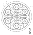
- is a sectioned end view of the engine of Figure 1, taken along the section line 2-2 shown in Figure 1, and on a larger scale;
- Figure 3
- is a schematic developed view of the engine of Figures 1 and 2, taken along the development line 3-3 shown in Figure 2;
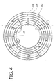
- Figure 4
- is a phase diagram to illustrate one mode of operation of the engine of Figures 1 to 3;
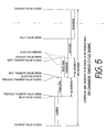
- Figure 5
- is a more detailed phase diagram to illustrate the operation of one of the combustion chambers of the engine of Figures 1 to 3;
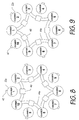
- Figure 6
- is similar to Figure 3, but for a different configuration of engine;
- Figure 7
- is a phase diagram to illustrate the operation of the combustion chambers of the engine of Figure 6;
- Figure 8
- is a schematic developed view taken on the line 8-8 in Figure 6; and
- Figure 9
- is a schematic developed view taken on the line 9-9 in Figure 6.
- Referring to the drawings, a
gas turbine engine 10 has acompressor 12,combustion stage 14 andturbine 16. Thecompressor 12 andturbine 16 may be of generally conventional design/construction, and each may be a multi-stage unit. Theturbine 16 is typically connected to and drives thecompressor 12 throughshaft 18. A secondco-axial shaft 19 is provided for the operation and synchronisation of the auxiliary equipment, including the valves, the fuel injection system, the governor and the lubrication system.Shaft 18 and theco-axial shaft 19 are preferably connected by means of gearing or, in the case of stationary applications, theco-axial shaft 19 may be driven by external means, in which case, the governor must be driven by theshaft 18 in order to control the output speed. Theengine 10 may have a mechanical power take-off, for instance in stationary or marine applications, or it may be used as a turboprop engine or as a turbojet or in any other configuration of thrust producing engine. The novelty of theengine 10 lies primarily in the method of compounding in thecombustion stage 14. - In the configuration of Figures 1 to 3, the
combustion stage 14 has anenclosure 20, which houses a circular array of sixelongate combustion chambers 22a-f, or pressure vessels, with their longitudinal axes generally parallel to and arranged around theshafts - One end of each
combustion chamber 22a-f is connected via arespective inlet port 24 to a manifold 26 at the outlet of thecompressor 12. Eachinlet port 24 contains arespective inlet valve 28a-f which is operated by an inlet and transfervalve actuator mechanism 30 which may in turn be driven by theco-axial shaft 19. Eachinlet valve 28a-f may be a poppet valve which is forced open by theactuator mechanism 30, preferably by means of a cam and which is closed by a spring and which is assisted in remaining closed by the pressure in therespective combustion chamber 22a-f. Alternatively, other types of inlet valve may be employed including piston, rotary or sleeve operated valves. - The other end of each
combustion chamber 22a-f is connected via arespective exhaust port 32 to arespective segment 34a-f of anozzle ring 36 at the inlet to theturbine 16. Each exhaust port contains arespective exhaust valve 38a-f which is operated by anexhaust valve mechanism 40 which may in turn be driven by theco-axial shaft 19. Eachexhaust valve 38a-f may be a piston operated valve which is operated by theactuator mechanism 40, preferably by means of an eccentric or short stroke crank. Alternatively, other types of exhaust valve may be employed including poppet valves, rotary or sleeve operated valves. - Adjacent the exhaust end of each
combustion chamber 22a-f, a respectivefuel injection nozzle 42a-f is provided. The fuel injection nozzles are operated sequentially to inject diesel fuel into therespective combustion chambers 22a-f and their timing is controlled by afuel injection pump 43 driven by (and shown diagrammatically adjacent to)co-axial shaft 19. More than onefuel injection nozzle 42a-f may be provided to serve eachcombustion chamber 22a-f. Where theshafts fuel injection pump 43 may be an in-line fuel pump fitted with an integral governor, or a rotary distribution fuel pump, again with an integral governor. Alternatively, eachchamber 22a-f may be supplied with fuel using individual combined fuel pump/injector/nozzle units which in turn may be actuated byco-axial shaft 19, although such an arrangement would require a separate linked governor unit driven byshaft 18 in order to control the output speed. - Adjacent the inlet end of each combustion chamber (
e.g. chamber 22b), the combustion chamber is connected to the two adjacent combustion chambers (e.g. chambers respective transfer ports 44. Eachtransfer port 44 contains a respective transfer valve 46ab,46bc,46cd,46de,46ef,46fa which is operated by the inlet and transfervalve actuator mechanism 30. Each transfer valve 46ab,46bc,46cd,46de,46ef 46fa may be a piston valve which is operated by theactuator mechanism 30, preferably by means of an eccentric or short stroke crank. Alternatively, other types of transfer valve may be employed, including rotary or sleeve operated valves. - The inlet and transfer
valve actuator mechanism 30 has been considered above and shown schematically as a single unit operated by theco-axial shaft 19, but in practice separate units or mechanisms may be provided for actuating theinlet valves 28a-f and for actuating the transfer valves 46ab,46bc,46cd,46de,46ef,46fa. - Whilst it has been stated earlier that the
co-axial shaft 19 may either be driven through gearing by theshaft 18 or alternatively driven by external means, it is foreseen that provision would also be made for small variations in the respective valve timings and/or the respective fuel injection timings to meet different operating conditions, whilst still maintaining overall synchronisation of the auxiliary functions. It is also foreseen that the gear ratio betweenshaft 18 and the auxiliaryco-axial drive shaft 19 must be chosen such that the sequence of functions taking place in the combustion chambers will be out of synchronisation with, or multiples of, turbine rotational speed. This will ensure, for example, that the exhaust pulses will be constantly precessing in relation to the rotation, or multiples of revolutions, of the turbine blading, irrespective of the relative speeds or directions of shaft rotation, with a view to minimizing differential heat stresses. - The operation of the engine in the steady state of the six chamber configuration depicted in Figures 1 to 3 is now described assuming the starting point where, say,
- the
inlet valve 28c ofcombustion chamber 22c is open, itsexhaust valve 38c is on the verge of closing, and scavenging/cooling is about to cease; its transfer valve 46cd to thenext combustion chamber 22d is closed, its transfer valve 46bc from theprevious combustion chamber 22b is closed, no fuel is being injected atnozzle 42c; -
combustion chamber 22b leadscombustion chamber 22c by one sixth of a cycle; and -
combustion chamber 22d lags behindcombustion chamber 22c by one sixth of a cycle. - From the starting point, the operational phases A to E of the engine and the transitions between them, AB, BC, CD, DE, EA, insofar as the
combustion chamber 22c is concerned, are as follows: - Transition E-A: The
exhaust valve 38c closes to end the scavenging/cooling phase.- Phase A:
- Charge. Air continues to flow from the
compressor outlet manifold 26 through theopen inlet valve 28c into thecombustion chamber 22c until the pressure therein approaches that of the compressor outlet manifold. - Transition A-B:
- As the pressure in the
combustion chamber 22c generally reaches the compressor outlet manifold pressure, theinlet valve 28c closes and the transfer valve 46bc connecting with theprevious combustion chamber 22b opens. - Phase B:
- Compound. High pressure air and/or products of combustion flow from the
previous combustion chamber 22b (under approximately constant pressure conditions, maintained by fuel injection intocombustion chamber 22b), highly compressing the air incombustion chamber 22c and thereby substantially raising the temperature and pressure of the air charge incombustion chamber 22c, in anticipation of fuel injection. - Transition B-C.
- The transfer valve 46bc connecting with the
previous combustion chamber 22b closes. Fuel injection throughnozzle 42c intocombustion chamber 22c is initiated as the transfer valve 46cd connecting with thenext combustion chamber 22d opens. - Phase C:
- Combustion. Spontaneous ignition and combustion of the fuel/air takes place due to the existing high temperature and pressure in the
combustion chamber 22c. During combustion, high pressure air and/or products of combustion flow from thecombustion chamber 22c at approximately constant pressure into thenext combustion chamber 22d thereby providing the compounding pulse phase B for thenext combustion chamber 22d. - Transition C-D:
- As fuel injection from
nozzle 42c intocombustion chamber 22c satisfies the power requirement, and transfer to the next chamber is completed, the transfer valve 46cd connecting withcombustion chamber 22d closes. Theexhaust valve 38c opens. - Phase D:
- Exhaust. The high pressure residual products of combustion exhaust from the
combustion chamber 22c via thenozzle segment 34c to theturbine 16, and the pressure in thecombustion chamber 22c drops. - Transition D-E:
- The
inlet valve 28c opens. - Phase E:
- Scavenge. Air flows from the
compressor outlet manifold 26 through theinlet valve 28c, through thecombustion chamber 22c and theexhaust valve 38c thereby providing uniflow scavenge of thecombustion chamber 22c as well as providing cooling of thecombustion chamber 22c, theexhaust valve 38c, theturbine nozzle segment 34c and theturbine 16. - Transition E-A:
- This is a repeat of the transition E-A described at the beginning of this section.
- These phases for all six of the
combustion chambers 22a-f are shown in Figure 4. The relative lengths of the phases A to E are shown in Figure 4 as: A - 90°; B - 60°; C - 60°; D - 60°; and E - 90°. Nevertheless, the relative phases of A, D and E may vary considerably from those shown in Figure 4 although the compounding phase B and the combustion/transfer stage C are equal and limited to a maximum of 60° for the six combustion chamber configuration. - Figure 5 is a more detailed cycle diagram for any one of the combustion chambers 22. Again it shows that the compounding phase B and the combustion/transfer phase C are equal and limited to 60°. Fuel injection is shown diagrammatically to commence with the start of transfer and the rate of fuel injection is intended to maintain approximately constant pressure throughout the combustion and transfer phase. Normally, fuel injection will be completed before the end of the transfer phase, leaving sufficient tolerance for the governor to maintain the required speed/power output to match the engine load. It will be appreciated, however, that the configuration lends itself to a wide range of predetermined rates of fuel injection and timing such that under certain operating conditions injection may commence marginally before the start of transfer or it may end marginally after the end of transfer.
- As mentioned previously, each
combustion chamber 22a-f is elongate, ie its length between itsinlet ports 24 and itsexhaust ports 32 is substantially greater than its diameter or cross-sectional dimensions. Furthermore, thefuel injectors 42a-f and thetransfer ports 44 are located at opposite ends of each combustion chamber in order to provide optimum stratification between charge air and the residual products of combustion. When fuel is injected during the combustion phase C, combustion will tend to be concentrated at the same end as the injection nozzle whereas the charge air will be concentrated at the transfer port end of the chamber. Therefore, the air/gas which is transferred to the next combustion chamber in the sequence will have a high concentration of unburned air. For the six-combustion chamber single cycle engine shown in Figures 1, 2, 3, 4 and 5 the transfer ports are located adjacent the inlet ports and the injection nozzles are located adjacent the exhaust ports. Although this is the preferred arrangement, it will be appreciated that stratification can also be achieved if the injection nozzles are adjacent the inlet valves and the transfer ports are adjacent the exhaust valves. This is the subject of an alternative double cycle or duplex engine described later with reference to Figures 6 to 9. - The
engine 10 described above is preferably used at near constant speed and/or with near constant power output. It requires additional equipment for starting, such as a means of cranking it up to operating speed and may require the introduction or injection of a volatile fuel with synchronised spark ignition, until the compression ignition cycle can be sustained. - In the
engine 10 described above, theenclosure 20 may serve to collect used lubricating oil, for example on a dry sump basis, and to carry additional cooling air bled from the compressor and exhausted into a late turbine stage. This bleed air may be used for additional external cooling for the combustion chambers and, particularly for the transfer ports and their respective valves. Theenclosure 20 may also be used to contain and vent any gas leaks which may occur, for example at the inlet poppet valve stems or past the piston rings of the transfer and exhaust valves. The external surfaces of thecombustion chambers 22a-f may be provided with radial, longitudinal or spiral finning to assist in cooling and/or thecombustion chambers 22a-f may be provided with liquid cooling. In the case where longitudinal finning is employed, the combustion chambers may be formed by extrusion. - It is envisaged that the ideal application for this engine, to take full advantage of the improved efficiency, would be for electrical generation, particularly standby generation and for marine propulsion and the associated marine auxiliary engines, in each case using a geared mechanical power take-off. The engine may also be developed for aircraft propulsion, in turboprop, turbojet and other configurations, where the improved efficiency can be shown to offset any increase in weight and where the engine would provide improved safety by using high flashpoint, low grade diesel fuels.
- Many modifications and developments may be made to the embodiment of the invention described above. For instance, six
combustion chambers 22a-f have been shown merely by way of example, and other numbers of combustion chambers may be provided. As previously stated the auxiliary functions including the valves and fuel injection equipment may be operated by the co-axial gear drivenshaft 19 or, in stationary installations, theco-axial shaft 19 may be driven by external means such as an electric motor so that the speed of operation of the valves and injection equipment can be controlled more easily independently of the speed of thegas turbine shaft 18. The speed of such a motor may be controlled so as to provide precession between the working cycles of the combustion chambers and the turbine. In either case, the governor must be linked to theshaft 18 in order to control the output speed. Whether theshaft 19 is linked mechanically through gearing toshaft 18, or driven by external means, it is foreseen that the absolute and/or the relative timing of the auxiliaries may be varied, for example by providing automatic or manually-operable advance/retard mechanisms or systems, to fine tune the engine performance in respect of variations in load/speed. - In the embodiment described above, the combustion chambers are operated in a single cycle, and it will be appreciated that this produces an unbalanced axial load on the turbine. Alternatively, the combustion chambers may be operated in a double cycle where an engine has say ten combustion chambers such that diametrically opposite chambers are synchronized by using double lobe cams to actuate opposing valves, instead of eccentrics or short stroke cranks. Accordingly, it will be appreciated that, at any time when one of the combustion chambers is in its exhaust phase, the diametrically opposite combustion chamber will also be in its exhaust phase such that the axial loads on the turbine are balanced. However, it will also be appreciated that the effective combustion and transfer phases are being shortened with the increase in number of chambers, in this case being limited to a maximum of 36°, so an alternative layout is proposed below and this is shown in Figures 6 to 9.
- Figures 6 to 9 show that a balanced arrangement can be achieved by providing say ten combustion chambers in a double series of five interposed chambers. In this example, alternate chambers are linked for transfer and this configuration allows a maximum of 72° for each combustion/transfer phase and also allows the use of eccentrics or short stroke cranks for the control of the transfer and exhaust valves. Odd numbered chambers 22o are connected to each other by transfer ports 44o and even numbered
chambers 22e are connected bytransfer ports 44e. The valve and injection timing is arranged such that diametrically opposite chambers are always performing the same operation and thereby preserve the axial balance. Other features of the engine of Figures 6 to 9 are referenced with the same reference numerals as those used above in relation to Figures 1 to 5. - It has been stated that the
shaft 18 may provide a direct drive between the turbine and the compressor, whilst gearing betweenconcentric shafts shaft 19, in which case there is no need for theshaft 18. Such an arrangement is preferred to allow for the pre-selection of optimum speed ratios between the compressor, the auxiliaries and the turbine. It also permits the use of short stroke cranks along theshaft 19 for the operation of the piston valves via connecting rods. - Although the turbine has been described above as a single unit, alternatively two turbines may be employed, one to drive the compressor and the auxiliaries, and the other to provide a mechanical output.
Claims (17)
- A method of operation of a gas turbine engine (10) having a compressor (12) for compressing air, a plurality of combustion chambers (22a-f) in which fuel mixed with the compressed air combusts, and a turbine (16) which is driven by the products of combustion, wherein:(i) each combustion chamber operates in a cycle comprising the phases of:A. charging the combustion chamber with a charge of compressed air from the compressor while preventing air from escaping from the combustion chamber;B. then compounding by charging with a compounding charge of gas to form a compounded charge;C. then commencing injection of fuel into the combustion chamber so that there is spontaneous ignition and combustion of the fuel with the compounded charge at generally constant pressure; andD. then exhausting the products of combustion to the turbine;(ii) the cycles of the combustion chambers are out of phase in a sequence; and(iii) part of the compounded charge and/or the products of combustion thereof in each combustion chamber during the combustion phase thereof is transferred before the exhaust phase thereof to the next combustion chamber in the sequence to provide the compounding charge for that next combustion chamber.
- A method as claimed in claim 1, wherein the cycle of each combustion chamber also includes a phase E, between its exhaust phase D and its charging phase A, of permitting scavenge/cooling air to flow through the combustion chamber from the compressor to the turbine.
- A method as claimed in claim 2, wherein, following the end of the scavenging/cooling phase, the duration of the charging phase is such that the pressure of the fresh air charge in the combustion chamber is increased and preferably maximised by a "ram" effect.
- A method as claimed in any preceding claim, wherein each combustion chamber is elongate.
- A method as claimed in claim 4, wherein:the charging with air takes place at or adjacent one end of each combustion chamber; andthe exhausting of the products of combustion takes place at or adjacent the opposite end of each combustion chamber.
- A method as claimed in claim 4 or 5, wherein:the transfer of the compounding charge takes place at or adjacent one end of each combustion chamber; andthe injection of fuel takes place at or adjacent the other end of each combustion chamber.
- A gas turbine engine (10) comprising:a compressor (12) for compressing air;a plurality of combustion chambers (22a-f) each having at least one fuel injector (42a-f) and in which fuel mixed with the compressed air can combust; anda turbine (16) which is driven by the products of combustion;wherein:each combustion chamber is connected to the compressor via a respective inlet port (24) having a respective inlet valve (28a-f);each combustion chamber is connected to the turbine via a respective exhaust port (32) having a respective exhaust valve(38a-f);the combustion chambers are arranged as at least one series and in the, or each, series are operable sequentially;each combustion chamber is connected to the next combustion chamber in the, or the respective, series via a respective transfer port (44) having a respective transfer valve (46ab,46,bc,46cd,46de,46ef,46fa); andthe engine further comprises means (30,40,43) for operating the valves and the injectors so that the engine operates according to the method as claimed in any preceding claim.
- An engine as claimed in claim 7, wherein the valve and injector operating means is operable so that, during the charging phase for each combustion chamber, the inlet valve for that chamber is open and the exhaust valve for that chamber is closed.
- An engine as claimed in claim 7 or 8 when dependent on claim 2, wherein the valve and injector operating means is operable so that, during the scavenge/cooling phase for each combustion chamber, the inlet valve and the exhaust valve for that chamber are both open.
- An engine as claimed in any of claims 7 to 9, wherein the compressor and the turbine each have housings that are fixed relative to the combustion chambers.
- An engine as claimed in any of claims 7 to 10, wherein each inlet valve, exhaust valve and/or transfer valve comprises a respective poppet valve, piston-operated valve, rotary valve or sleeve valve.
- An engine as claimed in any of claims 7 to 11, wherein the valve and injector operating means is mechanically driven by the turbine via at least one gearbox.
- An engine as claimed in any of claims 7 to 12, wherein the compressor is mechanically driven by the turbine via at least one gearbox.
- An engine as claimed in any of claims 7 to 13, wherein each combustion chamber is elongate.
- An engine as claimed in claim 14, wherein:each inlet port is disposed at or adjacent one end of the respective combustion chamber; andeach exhaust port is disposed at or adjacent the opposite end of the respective combustion chamber.
- An engine as claimed in claim 14 or 15, wherein:each transfer port is disposed at or adjacent one end of the respective combustion chambers; andeach fuel injector is disposed at or adjacent the opposite end of the respective combustion chamber.
- An engine as claimed in any of claims 7 to 16, further including a nozzle ring (36) between the exhaust ports and the turbine, the nozzle ring having a plurality of segments (34a-f) each corresponding to a respective one of the combustion chambers.
Applications Claiming Priority (3)
| Application Number | Priority Date | Filing Date | Title |
|---|---|---|---|
| GB0116507 | 2001-07-06 | ||
| GB0116507A GB2377257B (en) | 2001-07-06 | 2001-07-06 | Compound gas turbine engines and methods of operation thereof |
| PCT/GB2002/003018 WO2003004846A1 (en) | 2001-07-06 | 2002-07-01 | Compound gas turbine engines and methods of operation thereof |
Publications (2)
| Publication Number | Publication Date |
|---|---|
| EP1407127A1 EP1407127A1 (en) | 2004-04-14 |
| EP1407127B1 true EP1407127B1 (en) | 2007-03-14 |
Family
ID=9918016
Family Applications (1)
| Application Number | Title | Priority Date | Filing Date |
|---|---|---|---|
| EP02745559A Expired - Lifetime EP1407127B1 (en) | 2001-07-06 | 2002-07-01 | Compound gas turbine engines and methods of operation thereof |
Country Status (7)
| Country | Link |
|---|---|
| US (1) | US7000402B2 (en) |
| EP (1) | EP1407127B1 (en) |
| AT (1) | ATE356926T1 (en) |
| DE (1) | DE60218853T2 (en) |
| ES (1) | ES2283574T3 (en) |
| GB (1) | GB2377257B (en) |
| WO (1) | WO2003004846A1 (en) |
Families Citing this family (25)
| Publication number | Priority date | Publication date | Assignee | Title |
|---|---|---|---|---|
| FR2829528B1 (en) * | 2001-09-07 | 2004-02-27 | Bernard Gilbert Macarez | PULSOMOTOR-IMPULSE TURBOMOTOR-GAS TURBINE WITH IMPULSE COMBUSTION CHAMBER AND JET EXPANSION |
| GB0218849D0 (en) * | 2002-08-14 | 2002-09-25 | Rolls Royce Plc | Lubrication system for gas turbine engine |
| WO2004072451A1 (en) * | 2003-02-12 | 2004-08-26 | Ishikawajima-Harima Heavy Industries Co., Ltd. | Pulse detonation engine system for driving turbine |
| US7107773B2 (en) | 2003-09-04 | 2006-09-19 | Siemens Power Generation, Inc. | Turbine engine sequenced combustion |
| US6983586B2 (en) * | 2003-12-08 | 2006-01-10 | General Electric Company | Two-stage pulse detonation system |
| US7500348B2 (en) * | 2005-03-24 | 2009-03-10 | United Technologies Corporation | Pulse combustion device |
| US7448200B2 (en) * | 2005-03-24 | 2008-11-11 | United Technologies Corporation | Pulse combustion device |
| US7950215B2 (en) * | 2007-11-20 | 2011-05-31 | Siemens Energy, Inc. | Sequential combustion firing system for a fuel system of a gas turbine engine |
| US20090165438A1 (en) * | 2007-12-26 | 2009-07-02 | Occhipinti Anthony C | Pulse detonation engine |
| GB0822676D0 (en) * | 2008-12-12 | 2009-01-21 | Rolls Royce Plc | A gas turbine engine |
| FR2945316B1 (en) | 2009-01-27 | 2013-01-04 | Michel Aguilar | REACTOR, IN PARTICULAR REACTOR FOR AIRCRAFT |
| US20100242436A1 (en) * | 2009-03-31 | 2010-09-30 | General Electric Company | Modulation of inlet mass flow and resonance for a multi-tube pulse detonation engine system using phase shifted operation and detuning |
| US20110126510A1 (en) * | 2009-11-30 | 2011-06-02 | General Electric Company | Pulse detonation combustor |
| CN101718236A (en) * | 2010-02-10 | 2010-06-02 | 周林 | Multitube pulse detonation combustion chamber communicated with jet deflector |
| US9217389B1 (en) * | 2011-11-10 | 2015-12-22 | Blue Origin, Llc | Rocket turbopump valves and associated systems and methods |
| CN104718354A (en) * | 2012-07-24 | 2015-06-17 | 布兰特·W-T·李 | Internal detonation engine, hybrid engines including the same, and methods of making and using the same |
| DE102015200964A1 (en) * | 2015-01-21 | 2016-07-21 | Freie Universität Berlin | Combustor system for a gas turbine and method for combusting a combustible mixture in a combustion chamber |
| FR3032024B1 (en) * | 2015-01-26 | 2018-05-18 | Safran | COMBUSTION MODULE WITH CONSTANT VOLUME FOR TURBOMACHINE COMPRISING COMMUNICATION IGNITION |
| WO2016181307A1 (en) | 2015-05-11 | 2016-11-17 | Devcon Engineering Gerhard Schober | Turbine |
| FR3037384B1 (en) * | 2015-06-11 | 2017-06-23 | Turbomeca | TURBOMACHINE HVAC COMBUSTION CHAMBER MODULE COMPRISING A COMBUSTION CHAMBER |
| US20180179952A1 (en) * | 2016-12-23 | 2018-06-28 | General Electric Company | Rotating detonation engine and method of operating same |
| FR3092615B1 (en) * | 2019-02-13 | 2021-01-22 | Safran Aircraft Engines | Aircraft turbine engine HVAC combustion module comprising independent chamber subassemblies |
| FR3098859B1 (en) * | 2019-07-15 | 2023-04-28 | Safran Aircraft Engines | CONSTANT VOLUME TURBOMACHINE COMBUSTION CHAMBER |
| US11174966B1 (en) | 2020-03-09 | 2021-11-16 | Blue Origin, Llc | Fluid damped check valve, and associated systems and mei'hods |
| US11391243B1 (en) | 2020-03-09 | 2022-07-19 | Blue Origin, Llc | Seal for gimbaling and/or fixed rocket engine nozzles, and associated systems and methods |
Family Cites Families (15)
| Publication number | Priority date | Publication date | Assignee | Title |
|---|---|---|---|---|
| US1903292A (en) * | 1933-04-04 | Explosion tubbinb | ||
| DE383286C (en) * | 1921-08-19 | 1923-10-12 | Alfred Krone | Explosion turbine |
| GB296267A (en) | 1927-06-23 | 1928-08-30 | Holzwarth Gas Turbine Company | Improvements in compound gas turbine and method of producing power therewith |
| DE515635C (en) * | 1928-08-05 | 1931-01-08 | Siemens Schuckertwerke Akt Ges | Internal combustion engine with several annularly arranged combustion chambers that come into operation one after the other |
| GB646302A (en) * | 1947-12-31 | 1950-11-22 | Marxer Dr | Explosion fuel turbine and method for operating the same |
| US2579321A (en) * | 1948-04-09 | 1951-12-18 | Nina K Guercken | Apparatus for producing gas under pressure |
| US2705867A (en) * | 1949-06-30 | 1955-04-12 | Curtiss Wright Corp | Engine having a rotor with a plurality of circumferentially-spaced combustion chambers |
| GB710252A (en) * | 1950-05-25 | 1954-06-09 | Napier & Son Ltd | Improvements in or relating to power plants incorporating gas turbines |
| US2937498A (en) * | 1953-01-13 | 1960-05-24 | Fritz A F Schmidt | Mechanically controlled multistage combustion chambers for gas-impulsetype engines and improved discharge control therefor |
| DE1014794B (en) * | 1953-11-25 | 1957-08-29 | Snecma | Intermittent gas generator, especially for jet engines |
| FR1131310A (en) * | 1955-09-19 | 1957-02-20 | Gas turbine | |
| GB892143A (en) * | 1958-01-20 | 1962-03-21 | Robert Lalonde | A combustion gas generator |
| US4693075A (en) | 1984-10-31 | 1987-09-15 | Andrew Sabatiuk | Gas turbine engines employing fixed volume combustion |
| US5237811A (en) * | 1990-12-26 | 1993-08-24 | Stockwell James K | Rotary internal combustion engine apparatus |
| US5901550A (en) * | 1993-04-14 | 1999-05-11 | Adroit Systems, Inc. | Liquid fueled pulse detonation engine with controller and inlet and exit valves |
-
2001
- 2001-07-06 GB GB0116507A patent/GB2377257B/en not_active Expired - Fee Related
-
2002
- 2002-07-01 EP EP02745559A patent/EP1407127B1/en not_active Expired - Lifetime
- 2002-07-01 DE DE60218853T patent/DE60218853T2/en not_active Expired - Fee Related
- 2002-07-01 ES ES02745559T patent/ES2283574T3/en not_active Expired - Lifetime
- 2002-07-01 WO PCT/GB2002/003018 patent/WO2003004846A1/en active IP Right Grant
- 2002-07-01 US US10/482,604 patent/US7000402B2/en not_active Expired - Fee Related
- 2002-07-01 AT AT02745559T patent/ATE356926T1/en not_active IP Right Cessation
Also Published As
| Publication number | Publication date |
|---|---|
| ES2283574T3 (en) | 2007-11-01 |
| DE60218853T2 (en) | 2007-12-13 |
| GB2377257B (en) | 2004-09-01 |
| US20040154306A1 (en) | 2004-08-12 |
| GB0116507D0 (en) | 2001-08-29 |
| US7000402B2 (en) | 2006-02-21 |
| WO2003004846A1 (en) | 2003-01-16 |
| EP1407127A1 (en) | 2004-04-14 |
| ATE356926T1 (en) | 2007-04-15 |
| GB2377257A (en) | 2003-01-08 |
| DE60218853D1 (en) | 2007-04-26 |
Similar Documents
| Publication | Publication Date | Title |
|---|---|---|
| EP1407127B1 (en) | Compound gas turbine engines and methods of operation thereof | |
| US4336686A (en) | Constant volume, continuous external combustion rotary engine with piston compressor and expander | |
| US20050257523A1 (en) | Afterburning, recuperated, positive displacement engine | |
| RU2516769C2 (en) | Intermittent internal combustion gas turbine | |
| US4873825A (en) | Positive displacement engine compounded with a gas turbine engine | |
| US7621253B2 (en) | Internal turbine-like toroidal combustion engine | |
| EP0187839B1 (en) | Rotary positive displacement machine | |
| US6314925B1 (en) | Two-stroke internal combustion engine with recuperator in cylinder head | |
| US2421868A (en) | Barrel type engine | |
| US3085392A (en) | Internal combustion engines | |
| WO2014107458A2 (en) | Circulating piston engine | |
| EP0101206B1 (en) | High compression gas turbine engine | |
| CA2998236A1 (en) | Engine assembly with intercooler | |
| US5507142A (en) | Hybrid steam engine | |
| WO2003046347A1 (en) | Two-stroke recuperative engine | |
| CN113167172A (en) | Rotor type internal combustion engine and method of operating the same | |
| TW201413102A (en) | Internal detonation engine, hybrid engines including the same, and methods of making and using the same | |
| EP3953573B1 (en) | Improved rotating combustion machine | |
| RU2729311C1 (en) | Hybrid turbofan plant with built-in rotor ice | |
| WO1984004779A1 (en) | Internal combustion engine | |
| RU2774091C1 (en) | Gas turbine engine | |
| KR20080038273A (en) | Steam enhanced double piston cycle engine | |
| PL145453B2 (en) | Turbine combustion engine in particular for powering vehicles | |
| RU2466284C1 (en) | Opposed internal combustion engine | |
| RU2242629C1 (en) | Detonation combustion jet engine |
Legal Events
| Date | Code | Title | Description |
|---|---|---|---|
| PUAI | Public reference made under article 153(3) epc to a published international application that has entered the european phase |
Free format text: ORIGINAL CODE: 0009012 |
|
| 17P | Request for examination filed |
Effective date: 20040203 |
|
| AK | Designated contracting states |
Kind code of ref document: A1 Designated state(s): AT BE BG CH CY CZ DE DK EE ES FI FR GB GR IE IT LI LU MC NL PT SE SK TR |
|
| AX | Request for extension of the european patent |
Extension state: AL LT LV MK RO SI |
|
| 17Q | First examination report despatched |
Effective date: 20040721 |
|
| RAP3 | Party data changed (applicant data changed or rights of an application transferred) |
Owner name: BENIANS, HUBERT MICHAEL |
|
| RIN1 | Information on inventor provided before grant (corrected) |
Inventor name: BENIANS, HUBERT MICHAEL |
|
| GRAP | Despatch of communication of intention to grant a patent |
Free format text: ORIGINAL CODE: EPIDOSNIGR1 |
|
| GRAS | Grant fee paid |
Free format text: ORIGINAL CODE: EPIDOSNIGR3 |
|
| GRAA | (expected) grant |
Free format text: ORIGINAL CODE: 0009210 |
|
| AK | Designated contracting states |
Kind code of ref document: B1 Designated state(s): AT BE BG CH CY CZ DE DK EE ES FI FR GB GR IE IT LI LU MC NL PT SE SK TR |
|
| PG25 | Lapsed in a contracting state [announced via postgrant information from national office to epo] |
Ref country code: BE Free format text: LAPSE BECAUSE OF FAILURE TO SUBMIT A TRANSLATION OF THE DESCRIPTION OR TO PAY THE FEE WITHIN THE PRESCRIBED TIME-LIMIT Effective date: 20070314 Ref country code: FI Free format text: LAPSE BECAUSE OF FAILURE TO SUBMIT A TRANSLATION OF THE DESCRIPTION OR TO PAY THE FEE WITHIN THE PRESCRIBED TIME-LIMIT Effective date: 20070314 Ref country code: LI Free format text: LAPSE BECAUSE OF FAILURE TO SUBMIT A TRANSLATION OF THE DESCRIPTION OR TO PAY THE FEE WITHIN THE PRESCRIBED TIME-LIMIT Effective date: 20070314 Ref country code: AT Free format text: LAPSE BECAUSE OF FAILURE TO SUBMIT A TRANSLATION OF THE DESCRIPTION OR TO PAY THE FEE WITHIN THE PRESCRIBED TIME-LIMIT Effective date: 20070314 |
|
| REG | Reference to a national code |
Ref country code: GB Ref legal event code: FG4D |
|
| REG | Reference to a national code |
Ref country code: CH Ref legal event code: EP |
|
| REF | Corresponds to: |
Ref document number: 60218853 Country of ref document: DE Date of ref document: 20070426 Kind code of ref document: P |
|
| REG | Reference to a national code |
Ref country code: IE Ref legal event code: FG4D |
|
| PG25 | Lapsed in a contracting state [announced via postgrant information from national office to epo] |
Ref country code: SE Free format text: LAPSE BECAUSE OF FAILURE TO SUBMIT A TRANSLATION OF THE DESCRIPTION OR TO PAY THE FEE WITHIN THE PRESCRIBED TIME-LIMIT Effective date: 20070614 |
|
| PG25 | Lapsed in a contracting state [announced via postgrant information from national office to epo] |
Ref country code: PT Free format text: LAPSE BECAUSE OF FAILURE TO SUBMIT A TRANSLATION OF THE DESCRIPTION OR TO PAY THE FEE WITHIN THE PRESCRIBED TIME-LIMIT Effective date: 20070814 |
|
| REG | Reference to a national code |
Ref country code: CH Ref legal event code: PL Ref country code: CH Ref legal event code: AEN Free format text: DAS PATENT IST AUF GRUND DES WEITERBEHANDLUNGSANTRAGS VOM 26.07.2007 REAKTIVIERT WORDEN. |
|
| ET | Fr: translation filed | ||
| REG | Reference to a national code |
Ref country code: ES Ref legal event code: FG2A Ref document number: 2283574 Country of ref document: ES Kind code of ref document: T3 |
|
| PG25 | Lapsed in a contracting state [announced via postgrant information from national office to epo] |
Ref country code: SK Free format text: LAPSE BECAUSE OF FAILURE TO SUBMIT A TRANSLATION OF THE DESCRIPTION OR TO PAY THE FEE WITHIN THE PRESCRIBED TIME-LIMIT Effective date: 20070314 |
|
| PG25 | Lapsed in a contracting state [announced via postgrant information from national office to epo] |
Ref country code: CZ Free format text: LAPSE BECAUSE OF FAILURE TO SUBMIT A TRANSLATION OF THE DESCRIPTION OR TO PAY THE FEE WITHIN THE PRESCRIBED TIME-LIMIT Effective date: 20070314 |
|
| PLBE | No opposition filed within time limit |
Free format text: ORIGINAL CODE: 0009261 |
|
| STAA | Information on the status of an ep patent application or granted ep patent |
Free format text: STATUS: NO OPPOSITION FILED WITHIN TIME LIMIT |
|
| PG25 | Lapsed in a contracting state [announced via postgrant information from national office to epo] |
Ref country code: DK Free format text: LAPSE BECAUSE OF FAILURE TO SUBMIT A TRANSLATION OF THE DESCRIPTION OR TO PAY THE FEE WITHIN THE PRESCRIBED TIME-LIMIT Effective date: 20070314 |
|
| 26N | No opposition filed |
Effective date: 20071217 |
|
| PG25 | Lapsed in a contracting state [announced via postgrant information from national office to epo] |
Ref country code: GR Free format text: LAPSE BECAUSE OF FAILURE TO SUBMIT A TRANSLATION OF THE DESCRIPTION OR TO PAY THE FEE WITHIN THE PRESCRIBED TIME-LIMIT Effective date: 20070615 Ref country code: MC Free format text: LAPSE BECAUSE OF NON-PAYMENT OF DUE FEES Effective date: 20070731 |
|
| PG25 | Lapsed in a contracting state [announced via postgrant information from national office to epo] |
Ref country code: IE Free format text: LAPSE BECAUSE OF NON-PAYMENT OF DUE FEES Effective date: 20070702 |
|
| PGFP | Annual fee paid to national office [announced via postgrant information from national office to epo] |
Ref country code: CH Payment date: 20080724 Year of fee payment: 7 Ref country code: ES Payment date: 20080723 Year of fee payment: 7 |
|
| PGFP | Annual fee paid to national office [announced via postgrant information from national office to epo] |
Ref country code: FR Payment date: 20080718 Year of fee payment: 7 Ref country code: IT Payment date: 20080726 Year of fee payment: 7 Ref country code: NL Payment date: 20080722 Year of fee payment: 7 |
|
| PGFP | Annual fee paid to national office [announced via postgrant information from national office to epo] |
Ref country code: GB Payment date: 20080731 Year of fee payment: 7 |
|
| PG25 | Lapsed in a contracting state [announced via postgrant information from national office to epo] |
Ref country code: EE Free format text: LAPSE BECAUSE OF FAILURE TO SUBMIT A TRANSLATION OF THE DESCRIPTION OR TO PAY THE FEE WITHIN THE PRESCRIBED TIME-LIMIT Effective date: 20070314 |
|
| PGFP | Annual fee paid to national office [announced via postgrant information from national office to epo] |
Ref country code: DE Payment date: 20080924 Year of fee payment: 7 |
|
| PG25 | Lapsed in a contracting state [announced via postgrant information from national office to epo] |
Ref country code: CY Free format text: LAPSE BECAUSE OF FAILURE TO SUBMIT A TRANSLATION OF THE DESCRIPTION OR TO PAY THE FEE WITHIN THE PRESCRIBED TIME-LIMIT Effective date: 20070314 |
|
| PG25 | Lapsed in a contracting state [announced via postgrant information from national office to epo] |
Ref country code: LU Free format text: LAPSE BECAUSE OF NON-PAYMENT OF DUE FEES Effective date: 20070701 Ref country code: BG Free format text: LAPSE BECAUSE OF FAILURE TO SUBMIT A TRANSLATION OF THE DESCRIPTION OR TO PAY THE FEE WITHIN THE PRESCRIBED TIME-LIMIT Effective date: 20070614 |
|
| PG25 | Lapsed in a contracting state [announced via postgrant information from national office to epo] |
Ref country code: TR Free format text: LAPSE BECAUSE OF FAILURE TO SUBMIT A TRANSLATION OF THE DESCRIPTION OR TO PAY THE FEE WITHIN THE PRESCRIBED TIME-LIMIT Effective date: 20070314 |
|
| REG | Reference to a national code |
Ref country code: CH Ref legal event code: PL |
|
| GBPC | Gb: european patent ceased through non-payment of renewal fee |
Effective date: 20090701 |
|
| NLV4 | Nl: lapsed or anulled due to non-payment of the annual fee |
Effective date: 20100201 |
|
| REG | Reference to a national code |
Ref country code: FR Ref legal event code: ST Effective date: 20100331 |
|
| PG25 | Lapsed in a contracting state [announced via postgrant information from national office to epo] |
Ref country code: CH Free format text: LAPSE BECAUSE OF NON-PAYMENT OF DUE FEES Effective date: 20090731 Ref country code: FR Free format text: LAPSE BECAUSE OF NON-PAYMENT OF DUE FEES Effective date: 20090731 Ref country code: LI Free format text: LAPSE BECAUSE OF NON-PAYMENT OF DUE FEES Effective date: 20090731 |
|
| PG25 | Lapsed in a contracting state [announced via postgrant information from national office to epo] |
Ref country code: GB Free format text: LAPSE BECAUSE OF NON-PAYMENT OF DUE FEES Effective date: 20090701 |
|
| PG25 | Lapsed in a contracting state [announced via postgrant information from national office to epo] |
Ref country code: DE Free format text: LAPSE BECAUSE OF NON-PAYMENT OF DUE FEES Effective date: 20100202 |
|
| REG | Reference to a national code |
Ref country code: ES Ref legal event code: FD2A Effective date: 20090702 |
|
| PG25 | Lapsed in a contracting state [announced via postgrant information from national office to epo] |
Ref country code: ES Free format text: LAPSE BECAUSE OF NON-PAYMENT OF DUE FEES Effective date: 20090702 |
|
| PG25 | Lapsed in a contracting state [announced via postgrant information from national office to epo] |
Ref country code: IT Free format text: LAPSE BECAUSE OF NON-PAYMENT OF DUE FEES Effective date: 20090701 |
|
| PG25 | Lapsed in a contracting state [announced via postgrant information from national office to epo] |
Ref country code: NL Free format text: LAPSE BECAUSE OF NON-PAYMENT OF DUE FEES Effective date: 20100201 |