EP1406041B1 - Dispositif de sécurité pour cartouche perforable - Google Patents
Dispositif de sécurité pour cartouche perforable Download PDFInfo
- Publication number
- EP1406041B1 EP1406041B1 EP03292433A EP03292433A EP1406041B1 EP 1406041 B1 EP1406041 B1 EP 1406041B1 EP 03292433 A EP03292433 A EP 03292433A EP 03292433 A EP03292433 A EP 03292433A EP 1406041 B1 EP1406041 B1 EP 1406041B1
- Authority
- EP
- European Patent Office
- Prior art keywords
- strip
- cartridge
- disposable
- pressurised fluid
- cartridge according
- Prior art date
- Legal status (The legal status is an assumption and is not a legal conclusion. Google has not performed a legal analysis and makes no representation as to the accuracy of the status listed.)
- Expired - Lifetime
Links
Images





Classifications
-
- F—MECHANICAL ENGINEERING; LIGHTING; HEATING; WEAPONS; BLASTING
- F17—STORING OR DISTRIBUTING GASES OR LIQUIDS
- F17C—VESSELS FOR CONTAINING OR STORING COMPRESSED, LIQUEFIED OR SOLIDIFIED GASES; FIXED-CAPACITY GAS-HOLDERS; FILLING VESSELS WITH, OR DISCHARGING FROM VESSELS, COMPRESSED, LIQUEFIED, OR SOLIDIFIED GASES
- F17C13/00—Details of vessels or of the filling or discharging of vessels
- F17C13/12—Arrangements or mounting of devices for preventing or minimising the effect of explosion ; Other safety measures
-
- F—MECHANICAL ENGINEERING; LIGHTING; HEATING; WEAPONS; BLASTING
- F17—STORING OR DISTRIBUTING GASES OR LIQUIDS
- F17C—VESSELS FOR CONTAINING OR STORING COMPRESSED, LIQUEFIED OR SOLIDIFIED GASES; FIXED-CAPACITY GAS-HOLDERS; FILLING VESSELS WITH, OR DISCHARGING FROM VESSELS, COMPRESSED, LIQUEFIED, OR SOLIDIFIED GASES
- F17C3/00—Vessels not under pressure
-
- F—MECHANICAL ENGINEERING; LIGHTING; HEATING; WEAPONS; BLASTING
- F17—STORING OR DISTRIBUTING GASES OR LIQUIDS
- F17C—VESSELS FOR CONTAINING OR STORING COMPRESSED, LIQUEFIED OR SOLIDIFIED GASES; FIXED-CAPACITY GAS-HOLDERS; FILLING VESSELS WITH, OR DISCHARGING FROM VESSELS, COMPRESSED, LIQUEFIED, OR SOLIDIFIED GASES
- F17C2201/00—Vessel construction, in particular geometry, arrangement or size
- F17C2201/01—Shape
- F17C2201/0104—Shape cylindrical
- F17C2201/0109—Shape cylindrical with exteriorly curved end-piece
-
- F—MECHANICAL ENGINEERING; LIGHTING; HEATING; WEAPONS; BLASTING
- F17—STORING OR DISTRIBUTING GASES OR LIQUIDS
- F17C—VESSELS FOR CONTAINING OR STORING COMPRESSED, LIQUEFIED OR SOLIDIFIED GASES; FIXED-CAPACITY GAS-HOLDERS; FILLING VESSELS WITH, OR DISCHARGING FROM VESSELS, COMPRESSED, LIQUEFIED, OR SOLIDIFIED GASES
- F17C2201/00—Vessel construction, in particular geometry, arrangement or size
- F17C2201/01—Shape
- F17C2201/0104—Shape cylindrical
- F17C2201/0114—Shape cylindrical with interiorly curved end-piece
-
- F—MECHANICAL ENGINEERING; LIGHTING; HEATING; WEAPONS; BLASTING
- F17—STORING OR DISTRIBUTING GASES OR LIQUIDS
- F17C—VESSELS FOR CONTAINING OR STORING COMPRESSED, LIQUEFIED OR SOLIDIFIED GASES; FIXED-CAPACITY GAS-HOLDERS; FILLING VESSELS WITH, OR DISCHARGING FROM VESSELS, COMPRESSED, LIQUEFIED, OR SOLIDIFIED GASES
- F17C2201/00—Vessel construction, in particular geometry, arrangement or size
- F17C2201/05—Size
- F17C2201/058—Size portable (<30 l)
-
- F—MECHANICAL ENGINEERING; LIGHTING; HEATING; WEAPONS; BLASTING
- F17—STORING OR DISTRIBUTING GASES OR LIQUIDS
- F17C—VESSELS FOR CONTAINING OR STORING COMPRESSED, LIQUEFIED OR SOLIDIFIED GASES; FIXED-CAPACITY GAS-HOLDERS; FILLING VESSELS WITH, OR DISCHARGING FROM VESSELS, COMPRESSED, LIQUEFIED, OR SOLIDIFIED GASES
- F17C2203/00—Vessel construction, in particular walls or details thereof
- F17C2203/06—Materials for walls or layers thereof; Properties or structures of walls or their materials
- F17C2203/0634—Materials for walls or layers thereof
- F17C2203/0636—Metals
-
- F—MECHANICAL ENGINEERING; LIGHTING; HEATING; WEAPONS; BLASTING
- F17—STORING OR DISTRIBUTING GASES OR LIQUIDS
- F17C—VESSELS FOR CONTAINING OR STORING COMPRESSED, LIQUEFIED OR SOLIDIFIED GASES; FIXED-CAPACITY GAS-HOLDERS; FILLING VESSELS WITH, OR DISCHARGING FROM VESSELS, COMPRESSED, LIQUEFIED, OR SOLIDIFIED GASES
- F17C2205/00—Vessel construction, in particular mounting arrangements, attachments or identifications means
- F17C2205/03—Fluid connections, filters, valves, closure means or other attachments
- F17C2205/0302—Fittings, valves, filters, or components in connection with the gas storage device
- F17C2205/0311—Closure means
- F17C2205/032—Closure means pierceable
-
- F—MECHANICAL ENGINEERING; LIGHTING; HEATING; WEAPONS; BLASTING
- F17—STORING OR DISTRIBUTING GASES OR LIQUIDS
- F17C—VESSELS FOR CONTAINING OR STORING COMPRESSED, LIQUEFIED OR SOLIDIFIED GASES; FIXED-CAPACITY GAS-HOLDERS; FILLING VESSELS WITH, OR DISCHARGING FROM VESSELS, COMPRESSED, LIQUEFIED, OR SOLIDIFIED GASES
- F17C2205/00—Vessel construction, in particular mounting arrangements, attachments or identifications means
- F17C2205/03—Fluid connections, filters, valves, closure means or other attachments
- F17C2205/0302—Fittings, valves, filters, or components in connection with the gas storage device
- F17C2205/0323—Valves
- F17C2205/0335—Check-valves or non-return valves
-
- F—MECHANICAL ENGINEERING; LIGHTING; HEATING; WEAPONS; BLASTING
- F17—STORING OR DISTRIBUTING GASES OR LIQUIDS
- F17C—VESSELS FOR CONTAINING OR STORING COMPRESSED, LIQUEFIED OR SOLIDIFIED GASES; FIXED-CAPACITY GAS-HOLDERS; FILLING VESSELS WITH, OR DISCHARGING FROM VESSELS, COMPRESSED, LIQUEFIED, OR SOLIDIFIED GASES
- F17C2221/00—Handled fluid, in particular type of fluid
- F17C2221/03—Mixtures
- F17C2221/032—Hydrocarbons
- F17C2221/035—Propane butane, e.g. LPG, GPL
-
- F—MECHANICAL ENGINEERING; LIGHTING; HEATING; WEAPONS; BLASTING
- F17—STORING OR DISTRIBUTING GASES OR LIQUIDS
- F17C—VESSELS FOR CONTAINING OR STORING COMPRESSED, LIQUEFIED OR SOLIDIFIED GASES; FIXED-CAPACITY GAS-HOLDERS; FILLING VESSELS WITH, OR DISCHARGING FROM VESSELS, COMPRESSED, LIQUEFIED, OR SOLIDIFIED GASES
- F17C2223/00—Handled fluid before transfer, i.e. state of fluid when stored in the vessel or before transfer from the vessel
- F17C2223/01—Handled fluid before transfer, i.e. state of fluid when stored in the vessel or before transfer from the vessel characterised by the phase
- F17C2223/0146—Two-phase
- F17C2223/0153—Liquefied gas, e.g. LPG, GPL
-
- F—MECHANICAL ENGINEERING; LIGHTING; HEATING; WEAPONS; BLASTING
- F17—STORING OR DISTRIBUTING GASES OR LIQUIDS
- F17C—VESSELS FOR CONTAINING OR STORING COMPRESSED, LIQUEFIED OR SOLIDIFIED GASES; FIXED-CAPACITY GAS-HOLDERS; FILLING VESSELS WITH, OR DISCHARGING FROM VESSELS, COMPRESSED, LIQUEFIED, OR SOLIDIFIED GASES
- F17C2260/00—Purposes of gas storage and gas handling
- F17C2260/03—Dealing with losses
- F17C2260/035—Dealing with losses of fluid
- F17C2260/036—Avoiding leaks
-
- F—MECHANICAL ENGINEERING; LIGHTING; HEATING; WEAPONS; BLASTING
- F17—STORING OR DISTRIBUTING GASES OR LIQUIDS
- F17C—VESSELS FOR CONTAINING OR STORING COMPRESSED, LIQUEFIED OR SOLIDIFIED GASES; FIXED-CAPACITY GAS-HOLDERS; FILLING VESSELS WITH, OR DISCHARGING FROM VESSELS, COMPRESSED, LIQUEFIED, OR SOLIDIFIED GASES
- F17C2270/00—Applications
- F17C2270/07—Applications for household use
- F17C2270/0709—Camping gas
Definitions
- the invention applies to the field of pressurized fluid cartridges, in particular perforable cartridges for pressurized fluid.
- the applications of these pierceable cartridges are multiple. These cartridges are particularly adapted to be used for stoves, more generally for portable apparatus-type camping devices.
- the FR 1 433 490 proposes flow limiting devices for pierceable cartridges. These devices are intended to limit the flow that escapes from a perforated cartridge to prevent the formation of dangerous flame due to too much fluid flow, and to keep the fluid under pressure remaining in the cartridge for further use of the cartridge.
- the invention overcomes this problem.
- a disposable pressurized fluid cartridge includes a bottom, a peripheral side wall and an upper wall having a pierceable portion, and provided internally with a safety device adapted to oppose the escape of the pressurized fluid after perforation, that is to say, to remove or limit the escape of this fluid.
- the safety device comprises a resiliently flexible support piece bearing a seal, said support piece having at least two support points spaced apart from each other to bear against at least one inner wall and to exert a restoring force sealingly applying the seal against the upper wall, around said pierceable part, said support piece being able to move apart under the action of a thrust member introduced through said pierceable part to separate the seal from the upper wall.
- the support piece comprises a blade.
- the seal is a seal overmolded on the blade, the upper part of the seal, adapted to be applied against the upper wall, revealing a region of the upper face of the blade.
- the blade comprises a boss on which is placed the overmolded seal, the upper part of the seal revealing the upper face of the blade in the region of the bump.
- the upper portion of the seal comprises a ring having at least one end in sealing contact with the upper wall.
- the blade comprises a cup on its own upper face to receive the seal which has a toric configuration.
- the cup has a seat adapted to receive the O-ring and a concentric central well and of greater depth than the seat.
- the support piece is made of plastic.
- the support piece is metal.
- the blade comprises at each end complementary fastening means of depressions made opposite in the peripheral lateral wall of the cartridge and at a distance from the bottom of the cartridge, these depressions being made without protruding to the outside of the cartridge and these attachment means being adapted to cooperate with these depressions to define said support points.
- the blade comprises at each end complementary fastening means of depressions made opposite in the peripheral lateral wall of the cartridge and at a distance from the bottom of the cartridge, these depressions being made protruding to the outside of the cartridge and these attachment means being adapted to cooperate with these depressions to define said support points.
- the distance between the attachment means is greater than the distance between the corresponding depressions so that the blade is bent to exert said restoring force during the cooperation of the means of attachment. hangs with the depressions.
- the blade comprises at least two symmetrical branches on either side of the seal.
- Each branch of the blade is bent on both sides of a point of inflection and comprises a raised end adapted to cooperate with a recess formed at least partly in the peripheral side wall of the cartridge and at a distance from the bottom of the the cartridge to define said support points, each depression being made without projecting outwardly of the cartridge.
- the distance between the raised ends is equal to or greater than the distance between the corresponding depressions so that the blade is bent to exert said restoring force during the cooperation of the raised ends with the depressions.
- the blade includes a curved generally U-shaped portion springing.
- the blade comprises two symmetrical branches on either side of the seal, each branch of the blade being folded so as to follow at least partly the internal shape of the cartridge to the bottom, the end of each branch of the blade being adapted to rest on the bottom of the cartridge and forming one of said support points.
- each blade leg includes a generally U-shaped bent portion springing.
- each folded portion is followed by a hinge connecting the folded portion to a portion extending toward the bottom of the cartridge.
- the blade comprises a ring connecting the ends of the branches of the blade.
- the blade comprises at least one bar of length such that and positioned so that its ends touch the peripheral lateral wall of the cartridge and are fit to slide along this wall under the action of the organ thrust on the blade.
- the blade comprises a bar of length such that and positioned so that the ends touch the upper wall and are fit to slide along this wall under the action of the thrust member on the blade.
- the blade comprises two symmetrical branches on either side of the seal, each part of the blade being corrugated folded and terminating at one end, each end being adapted to be screwed in. screw in at least one groove, made by a fold of the upper wall of the cartridge, to form one of said points of support.
- each branch of the blade is bent dovetail and both ends are adapted to fit into the same annular groove surrounding the pierceable portion.
- the blade comprises two symmetrical branches on either side of the seal, each limb of the blade being corrugated folded and terminating at one end, each end being adapted to be secured to the upper wall of the cartridge to form one of said support points.
- each branch of the blade is bent in the general U-shape and both ends of the blade are welded to the top wall of the cartridge.
- a resiliently flexible blade bearing a seal said blade having at least two support points spaced apart from one another allowing it to exert an elastic restoring force on the seal.
- the blade comprises three branches starting from the joint in the form of a star.
- the seal is placed in the vicinity of a first end of the blade.
- the blade is folded so as to follow the internal shape of the cartridge to the bottom, the blade having a first fold adapted to bear on a first zone of the bottom and forming the first point of support and a second fold proper to rely on a second zone of the bottom and forming the second fulcrum, the first and second zones being opposite to the center of the bottom of the cartridge.
- the support piece is a support base comprising a holding base forming a clean base to bear against the bottom of the cartridge, at least two branches of a blade extending from the holding base and joining a central boss supporting the seal, each leg being secured to the holding base.
- At least two flexible blades integral with the holding base extend towards and around the central boss and come into contact around the pierceable portion of the cartridge.
- the invention also relates to a security device adapted to form part of a previously presented cartridge, comprising a resiliently flexible support piece bearing a seal, said support piece having at least two support points distant from one another. allowing to exert an elastic restoring force on the joint.
- the figure 1 represents a perforable cartridge 1 known from the state of the art and having a symmetry of revolution about the Y axis.
- This cartridge comprises a stamped part consisting of a cylindrical side wall 5 and a convex upper wall 3 convex towards the outside of the cartridge.
- the domed top wall is provided at its top and centrally with a recessed portion 10 convex towards the inside of the cartridge, this recessed portion being shaped spherical cap.
- This recessed portion 10 is adapted to be pierced at its center so as to form an orifice through which the pressurized fluid of the cartridge can escape.
- the cylindrical portion 5 of the cartridge is closed at its base by a convex bottom 7 inwardly.
- This form of perforable cartridge is particularly suitable for containing a fluid under pressure.
- the pressurized fluid contained in the cartridge is a combustible gas.
- the central zone of the recessed portion 10, where the perforation is made, is also called perforable part 11.
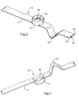
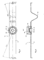
- FIGS. 2 to 5 illustrate a safety device according to a first embodiment of the invention, the figure 6 representing the blade of the safety device according to this embodiment.
- the safety device 12 comprises a blade 15 of elongated rectangular shape with two main faces (an upper face and a lower face) comprising along its length a generally U-shaped folded part, more precisely in the form of a V in the example of the Figures 2 to 6 .
- the blade 15 is provided symmetrically at each end of attachment means comprising tabs separated from each other by notches opening at the end of the blade. These tabs comprise a central tab 16 bent at least partly perpendicularly to the blade 15 and surrounded on both sides of tabs 19 unfolded.
- the blade 15 is provided in its middle with a molded seal 14 of generally cylindrical shape which completely surrounds the cross section of the blade so as to be secured to the blade.
- the seal comprises an upper portion on the side of the upper face of the blade and a lower portion on the side of the underside of the blade.
- the axis of revolution of the overmolded seal is perpendicular to the upper and lower faces of the blade.
- the upper portion of the overmolded seal 14 is recessed in its center at 24 so as to reveal a region of the upper face of the blade 15.
- the upper part of the overmolded seal 14 forms a ring 13 surrounding the recess 24.
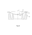
- FIGS. 20 to 24 are in section the recessed portion 10 of the cartridge and the ring 13 of the upper portion of the overmolded seal 14 bears against the upper part of the cartridge.
- the circular end 17-1 of the ring 13 is sealingly abutting around the perforable portion 11 against the recessed portion 10 of the cartridge.
- the circular end 17-1 of the ring 13 is sealingly abutting around the pierceable portion 11, against the wall of the cartridge surrounding the recessed portion 10.
- the ring 13 has at its end a circular shoulder defining two circular ends 17-4 and 17-5, each sealingly against the recessed portion 10 of the cartridge. These two circular ends form a double seal around the perforable part 11.
- the two ends 17-4 and 17-5 respectively bear against the recessed portion 10 of the cartridge and against the wall of the cartridge surrounding the recessed portion 10.
- the ring 13 has at its end a circular groove surrounded by two circular ends 17-2 and 17-3, each respectively sealingly against the recessed portion 10 of the cartridge and against the wall of the cartridge surrounding the recessed portion 10. These two ends form a double seal around the perforable part 11.
- the blade 15 comprises a domed generally cylindrical portion 20 also called bump.
- This curved portion can be advantageously carried out by embossing or stamping.
- the seal 14 is overmolded so as to be held fixed in translation on the blade.
- the seal consists only of an upper portion overmolded on the curved portion 20 of the blade as shown in FIGS. figures 11 and 12 , the upper part being hollowed in its center of to reveal a region of the upper face of the blade.
- the seal consists only of an overmolded upper portion 74 on a full boss 22 of the blade.
- Said overmolded upper portion 74 is recessed in its center and thus has a ring so as to reveal the upper surface of the boss (or boss) corresponding to a region of the upper face of the blade.
- the base of the overmolded upper portion 74 has a certain thickness so as to have a large contact surface with the side faces of the boss and the upper face of the blade.
- the full hump 22 can be made in a variety of ways including those presented on the Figures 17, 18 and 19 . So, the figure 17 represents a sectional hump whose side faces 23 have a right angle with the upper face of the blade.
- the figure 18 represents a boss 22 in section whose side faces 23 are inclined relative to the upper face of the blade.
- the figure 19 represents a boss 22 in section whose side faces 23 have a shoulder.
- the crown of the seal can be made according to the variants of embodiment of Figures 20 to 23 for example only.
- the recessed portion 24 of the overmolded seal 14 reveals the upper face of the blade in the region of the convex portion 20.
- the lower portion of the seal covering the underside of the blade has a substantially constant thickness and therefore has a concave portion 28 next to the concave part of the blade.
- the blade On the upper face of the blade, the blade carries a cup 30 placed in the middle. This cup can be fixed to the blade by welding or by any other method. This cup 30 is of a depth adequate to receive an O-ring 32.
- the cup has a seat 33 having a certain depth to receive the O-ring and a concentric central well 35 of greater depth than the seat 33.
- the blade 15 of the safety device 12 is elastically flexible. It can be made of metal, for example for the realization of Figures 2 to 5 .
- the blade 15 of the safety device 12 can also be made of plastic.
- the figure 8 illustrates the security device once set up inside a cartridge.
- the device is introduced and put in place inside the cartridge before the closure of the cartridge, which is carried out by assembling the bottom with the stamped part of the cartridge.
- the security device 12 once set up as shown on the figure 8 corresponds to the safety device 12 of the Figures 2 to 5 , the safety device according to the realization of the figure 7 can be placed in the same way on a cartridge before assembly of the bottom with the stamped part.
- the safety device 12 is placed inside the stamped part so that the blade follows the shape of the convex upper wall 3 of the cartridge 1.
- the ring 13 of the seal is applied against the convex upper wall and around the perforable portion 11 to provide a seal after removal of a member having perforated the perforable portion.
- the cartridge comprises, to receive each end of the blade, depressions made preferably opposite in the side wall of the cartridge and at a distance from the bottom of the cartridge, these depressions being advantageously formed without projecting towards the outside of the cartridge. .
- two recesses 34 form inward protrusions on which the unfolded tabs 19 rest respectively, the projections being spaced apart from each other so as to leave a space between them for the folded tab 16. This folded tab bears against the internal side wall of the cartridge between the two recesses.
- the pairs of recesses are made symmetrically with respect to the pierceable portion of the cartridge.
- the pairs of depressions are more particularly diametrically opposed.
- the attachment means of each end are complementary to the recesses 34 made in the side wall of the cartridge.
- the attachment means cooperate with the positioning means that are the depressions so that the blade has two points of support against at least one inner wall of the cartridge.
- the distance between the attachment means is greater than the distance between the corresponding recesses 34, symmetrically positioned in the cartridge.
- the blade 15 must be bent so as to follow the curvature of the curved upper wall 3 and to exert said restoring force during the cooperation of the attachment means with the depressions.
- the overmolded seal 24 is then applied against the convex upper wall 3 around the pierceable portion 11.
- the blade is placed in the cartridge so as to have a point of support at each of its ends and so as to exert a force which tends to press the seal against the convex upper wall 3.
- the blade is placed in the cartridge so that the region of the upper face of the blade released by the recessed portion 24 of the overmolded seal is opposite the pierceable portion 11 of the cartridge.
- the cartridge is then filled with fluid under pressure and the bottom is fixed on the stamped part of the cartridge for example by crimping.
- the tip when the cartridge is perforated by a tip in the zone 11 in the center of the portion 10, the tip is pressed against the region of the upper face of the blade left exposed.
- the force exerted by the tip being greater than the restoring force of the blade which tends to press the seal against the curved upper wall, the seal is pushed from this wall.
- the tip must maintain the force exerted on the safety device so as to release the pressurized fluid from the cartridge.
- the blade pushes the seal against the curved upper wall 3 by means of a restoring force.
- This safety device serves as a closing means when the perforated cartridge is removed from the device to which it is connected.
- the figure 9 illustrates a cartridge provided with a safety device according to a third embodiment.
- This safety device 40 comprises a blade 41 carrying a generally cylindrical seal 44 molded in the vicinity of an end 42 of the blade 41.
- the upper part of this seal 44 is recessed at its center to form a ring 49 and revealing a region of the upper face of the blade 41.
- the crown of the seal 44 is applied to the rounded upper wall 3 around the pierceable portion 11 so that the region of the upper face of the blade left exposed is placed in a screw With respect to the perforable portion 11.
- the blade 41 is folded so as to follow the internal shape of the convex upper wall 3 and then of the lateral wall 5 of the cartridge to the convex bottom 7 of the cartridge opposite to the curved upper wall, (or more precisely to the perforable part).
- the blade 41 has a first fold supported on a first zone of the convex bottom 7 of the cartridge and forming a first fulcrum.
- the blade 41 then follows the convex shape of the bottom of the cartridge before presenting a second fold 48 resting on a second zone of the bottom of the cartridge and forming a second fulcrum.
- the first and second areas of the bottom of the cartridge are opposite to the center of the bottom of the cartridge.
- the end 42 of the blade 41 tends to press the seal against the convex upper wall 3 of the cartridge thus exerting a restoring force.
- the security device 40 operates in the same manner as before.
- a tip can push the seal of the domed upper wall 3 by exerting an opposite force and greater than the restoring force of the blade on the region of the upper face of the blade left exposed.
- the return force of the blade tends to push the seal against the curved upper wall.
- the figure 10 illustrates a cartridge provided with a safety device according to a fourth embodiment.
- the blade is folded symmetrically, the seal 44 is overmolded in the middle. From this seal 44, one of the two symmetrical branches of the blade is described below.
- This blade branch is folded so as to follow the internal shape of the cartridge until bottom 7 opposite the curved upper wall, the end 58 of the branch of the blade being adapted to rest on the bottom 7 of the cartridge to form a fulcrum.
- the end 58 is advantageously folded to follow the shape of the bottom 7 of the cartridge.
- this blade branch comprises facing the wall 3 a folded portion generally U-shaped so as to act as a spring.
- the other blade branch is symmetrical with the blade branch that has been described.
- the symmetry of the safety device 50 gives stability to the safety device 50, the generally U-shaped symmetrical folded portions 54 and 56 are arranged on either side of the seal 44 so as to act as a spring. These folded parts are facing the curved upper wall 3. As in the previous device, the blade 51 exerts a restoring force which tends to press the seal against the convex upper wall 3 and around the perforable portion 11.
- the safety devices illustrated in a variant comprise a blade carrying a seal that can be made according to one of the variants presented above.
- the blade is placed in the cartridge so as to have a point of support at each of its ends and so as to exert a force which tends to press the seal against the convex upper wall 3.
- the blade is placed in the cartridge so that the region of the upper face of the blade released by the recessed portion of the overmolded seal is opposite the pierceable portion 11 of the cartridge.
- the Figures 11 to 13 present alternative embodiments of the safety device of the figure 8 once set up inside a cartridge.
- the cartridge comprises, to receive each end of the blade, recesses made in opposite preferably and in an inner wall, at the limit of the upper wall and the side wall of the cartridge and at a distance from the bottom of the cartridge, these depressions being advantageously formed without projecting towards the outside of the cartridge.
- Each depression 63 forms an inwardly projecting boss on which a raised end 65 of the safety device blade is supported.
- the depressions are made symmetrically with respect to the pierceable portion of the cartridge. For a cylindrical side wall of the cartridge, the depressions are more particularly diametrically opposed.
- the blade 61 has a molded seal 64 at its center having an axis of symmetry W.
- the blade 61 comprises at least two branches 66 symmetrical with respect to the axis W on either side of the overmolded seal 64.
- Each branch 66 of the blade has a double curvature. In other words, each branch 66 of the blade is flexed on either side of an inflection point (z and z ').
- each branch of the blade first follows the upper wall 3 of the cartridge and then, after the point of inflection, each branch of the blade is bent, more particularly straightened, so that its raised end 65 can abut against the depression 63 (or boss) made in the peripheral side wall 5 of the cartridge and at a distance from the bottom 7 of the cartridge.
- the cartridge comprises a lower peripheral side wall 5-1 and an upper peripheral side wall 5-2, the outside diameter ⁇ ext of the lower peripheral side wall 5-1 being smaller than the outside diameter of the side wall upper device 5-2.
- the cartridge can be formed in the upper peripheral side wall 5-2 of the recesses 73 projecting outwardly from the cartridge without these depressions protruding beyond the largest of the outer diameters ( ⁇ ext). In this way, the standards of size of a cartridge are respected.
- the figure 13 shows the realization of a first and a second recess pair opposite to respectively receive the first and the second end of the blade.
- the blade 71 comprises at each end complementary attachment means of the recesses 73 made opposite in the peripheral side wall 5 of the cartridge and at a distance from the bottom 7 of the cartridge. These attachment means are two lugs made at each end of the blade.
- the tabs 75 are inserted into the depressions to define the support points of the device.
- the distance between the pairs of legs of each end of the blade is greater than the distance between the corresponding depressions 73.
- the blade 71 must be bent to exert a restoring force. on the joint during the cooperation of the legs 75 with the depressions 73.
- the Figures 14 and 15 present alternative embodiments of the safety device once set up inside a cartridge.
- the convex upper wall of the cartridge comprises an elevated area relative to the remainder of the upper wall, this raised area surrounding and including the pierceable portion 11.
- the broken line represents the level of the domed upper wall of the cartridge in the previous embodiments . So as to keep a height requirement identical to the previous embodiments, the curved upper wall of the cartridge is lowered, only the raised area retains the height of the domed top wall of previous embodiments.
- the raised zone is preferably circular and is connected to the remainder of the upper wall by a fold of the upper wall forming an annular groove 82 of horizontal general direction inside the cartridge.
- the raised area may be of any other shape and be connected to the remainder of the upper wall by one or more grooves or vertical walls comprising depressions.
- the blade 81 carries an overmolded seal 44 for example.
- the blade comprises two symmetrical branches 84 on either side of the seal.
- Each branch 84 of the blade is corrugated and ends with a folded end 83.
- each branch 84 of the blade is folded into a dovetail so that once the safety device 80 is placed in the cartridge, the seal 44 is located mainly above the dovetailed folded branches.
- Each branch 84 ends with a complementary folded end of the annular groove and adapted to be inserted into the annular groove 82 to form one of the support points.
- the figure 15 another embodiment of a safety device 90.
- This embodiment provides a blade 91 carrying an overmolded seal 44.
- the blade 91 comprises two symmetrical branches 94 on either side of the seal. Each branch of the blade is corrugated folded and ends with an end 92. Each end is secured to the upper wall 3 of the cartridge to form one of the support points.
- each portion 94 of the blade is generally U-shaped.
- both ends 92 of the blade are welded to the upper wall 3 of the cartridge to form a support.
- the Figures 25 to 27 show an alternative embodiment of the safety device alone and once set up inside a cartridge.
- the blade is folded symmetrically and has a solid boss 22 receiving the seal 74 overmolded on the upper face of the blade and adapted to form a sealed contact around the pierceable portion 11 of the cartridge.
- the blade is folded on a portion 101 in the form of U inverted and is folded symmetrically to form two rounded 102 generally U-shaped overturned.
- the parts 102 serve to ensure a spring role of the blade.
- Each branch of the blade is folded so as to follow at least part of the internal shape of the cartridge to the bottom.
- the blade portions 102 are connected to portions 104 by a hinge 110.
- the portions 104 have ends 106 folded toward the interior of the device and adapted to abut the bottom 7 of the cartridge so as to each form a point support.
- the hinges 110 allow the portions 104 of the blade to be unfolded only to the outside of the device in the open position. These hinges 110 allow the blade to have a small footprint in case of storage before use in a perforable cartridge.
- parts 104 comprising ends 106 folded towards the outside of the device.
- the hinges 110 only allow the portions 104 of the blade to be folded inwardly of the device in the closed position.
- the blade variants described above may have hinges 110 as shown.
- an alternative embodiment consists of a blade comprising at least three blade branches interconnected at the joint, the blade having the shape of a star.
- Each end of the three branches cooperates with the side wall of the cartridge in the same manner as one of the ends of the blade of the previous embodiments.
- Each part of the branches of the blade is folded so as to follow at least partly the internal shape of the cartridge to the bottom.
- FIG. 28 to 30 An exemplary embodiment of a star-shaped blade is given to Figures 28 to 30 .
- a plate 115 in the form of a triangle comprises the full boss 22.
- Each branch is connected to the common plate 115, a branch having a portion 111 of connection to the plate 115, then a portion 112 in the form of an inverted rounded U ending by a portion 114 bearing on the bottom 7 of the cartridge.
- the blade is used as a spring means for exerting a restoring force sealingly applying the seal against the top wall of the cartridge.
- the Figures 31 and 32 have a device comprising a blade symmetrically folded into two branches.
- the blade comprises a plate 120 carrying a full boss 22 on which the overmolded seal 74 comes. From the common plate 120 is connected a portion 121, to which is connected a portion 122 in the form of an inverted rounded U ending in a part 124 bearing on the bottom 7 of the cartridge.
- the blade symmetrically presents the same parts from the common tray.
- the blade comprises a ring 125 connecting the symmetrical portions 124 at their base. This ring 125 is able to come into contact with the bottom 7 of the cartridge and allows the device to be centered in the cartridge.
- the Figures 33 to 36 present a device similar to the device of the Figures 31 and 32 , the same references designate elements in common.
- Plan AA will designate the plan of figure 33 in which the symmetrical parts of the blade extend.
- the device comprises two bars 130 and 132 parallel to each other and each positioned between a portion 121 and a portion 122 of a branch of the blade. Each bar extends in a plane perpendicular to the plane AA. These two bars are of such length that once the device in place in the cartridge, the ends of these bars touch the side wall 5 of the cartridge and are fit to slide along this side wall.
- these bars serve as lateral guides to the device when a force exerted by a tip pushes the seal of the pierceable portion 11 of the cartridge and when the device pushes the seal against the pierceable portion by exerting a restoring force.
- the Figures 37 to 40 present a device similar to the device of the Figures 33 to 36 , the same references designate elements in common.
- the device of Figures 37 to 40 does not have two bars but a bar 134 positioned against the plate 120 on the underside of the blade.
- the bar extends in a plane perpendicular to the plane AA. This bar is of such length that once the device is in place in the cartridge, the ends of this bar touch the upper wall 3 of the cartridge and are able to slide along the lateral parts of this upper wall 3 to laterally guide the device in a similar way to that of the bars of Figures 34 to 37 .
- the blade can be made for example of metal or plastic.
- the Figures 41 to 43 describe a first embodiment of a support base.
- the support base PS1 comprises a holding base 157 consisting of a base ring 148 adapted to come into contact with the bottom 7 of the cartridge, side uprights 159 that can be inclined towards the inside of the base as shown in FIGS. Figures 41 to 43 and an upper ring 158.
- the lateral uprights extend from the base ring 148 to the upper ring 158.
- Three branches 140, 141, 142 of a blade extend in undulating form from the holding base 157 to a central boss 146 supporting the seal (not shown), each leg being integral with the holding base, more particularly the upper ring 158, the branches joining the central boss 146. More specifically, the three branches are join in a cylinder 144 supporting the central boss 146.
- the seal is clean to come into sealing contact around the pierceable portion 11 of the cartridge.
- the undulating shape of the branches allows the latter to be elastically flexible and to exert a restoring force sealingly applying the seal against the upper wall of the cartridge, the central boss bearing the seal being thus clean to move away under the action of a thrust member introduced through the pierceable part to separate the seal from the upper wall 3.
- Flexible blades 150, 151, 152 are integral with the holding base, more particularly the upper ring 158, and extend towards the central boss 146. The curved free ends of the flexible blades come into contact against the upper wall 3 around the pierceable portion 11 of the cartridge and thus surround the seal.
- Each blade 150, 151, 152 is interposed between two branches.
- the flexible blades 150, 151, 152 are supported by respective reinforcements 154 inside the holding base 157, these reinforcements extending from the upper ring 148 to the free curved ends of the flexible blades 150, 151, 152 .
- the lateral uprights 159 are of the same width as the branches 140, 141, 142 and the blades 150, 151, 152 and are placed in the extension thereof.
- the Figures 44 to 46 describe a second embodiment of a support base.
- the PS2 support base comprises a holding base 167 consisting of a base ring 168 adapted to come into contact with the bottom 7 of the cartridge, side uprights 189 that can be inclined towards the inside of the base as shown in FIGS. Figures 44 to 46 and an upper ring 188.
- the lateral uprights extend from the base ring 168 to the upper ring 188.
- Three branches 160, 161, 162 of a blade extend from the holding base 167 until in a central boss 166 supporting the seal (not shown), each branch being secured to the holding base, and more particularly to the upper ring 188.
- the three branches are in the form of angular sectors whose vertices are located on the central boss 166.
- the three branches meet in a circular plate 164 supporting the central boss 166.
- the seal is able to come into sealing contact around the pierceable portion 11 of the cartridge.
- the undulating shape of the branches allows the latter to be elastically flexible and to exert a restoring force sealingly applying the seal against the upper wall of the cartridge, the central boss bearing the seal being thus clean to move away under the action of a thrust member introduced through the pierceable part to separate the seal from the upper wall 3.
- Flexible blades 180, 181, 182 are integral with the holding base, more particularly the upper ring 188, and extend towards the central boss 166. Their curved free end comes into contact against the upper wall 3 around the pierceable portion 11 of the cartridge and thus surround the seal.
- Each flexible blade 180, 181, 182 is interposed between two branches.
- the flexible blades 180, 181, 182 are supported by respective reinforcements 184 inside the holding base 167, these reinforcements extending from the upper ring 188 to the curved free ends of the flexible blades 180, 181, 182.
- the base ring has a diameter such that it comes into contact against the peripheral side wall 5 of the cartridge and thus serves as a centering ring of the device in the cartridge.
- the Figures 47 and 48 describe a third embodiment of a support base.
- the PS3 support base comprises a holding base 197 consisting of a base ring 208 adapted to come into contact with the bottom 7 of the cartridge, lateral uprights 199 that can be inclined outwards of the base as shown in FIGS. Figures 47 and 48 and an upper ring 188.
- the upper ring is adapted to come into contact with the peripheral side wall 5 of the cartridge as shown in FIG. figure 48 and thus serves as a centering ring of the device in the cartridge.
- the lateral uprights extend from the base ring 208 to the upper ring 198.
- Three branches 190, 191, 192 of a blade extend from the holding base 197 to a central boss 196 supporting the seal (Not shown), each branch being integral with the holding base, more particularly the base ring 208.
- the three branches meet in a cylinder 194 supporting the central boss 196.
- the seal is clean to come into contact sealed around the pierceable portion 11 of the cartridge.
- the undulating shape of the branches allows the latter to be elastically flexible and to exert a restoring force sealingly applying the seal against the upper wall of the cartridge, the central boss bearing the seal being thus clean to move away under the action of a thrust member introduced through the pierceable portion to separate the seal of the upper wall.
- the safety device comprises a support piece which is the generic term for a blade or a support base (PS1, PS2 and PS3) also comprising a blade.
- a "support piece” therefore designates a clean part to carry the seal and to bear against the inner surface of the cartridge.
- support piece designates only one part, or a combination of fixed parts between them before and after mounting the device in the cartridge.
- the described joint variants can be combined with the described support part variants.
- the blade can bear against the curved upper wall
- the recesses can be made for example at the base of the curved upper wall.
- the invention covers all combinations of joints and support pieces presented by way of example in the description so as to provide a safety device according to the invention.
- the invention also covers forms of support parts different from those presented but providing the same spring function to the safety device, that is to say the same function of exercising a restoring force on the seal.
Landscapes
- Engineering & Computer Science (AREA)
- Mechanical Engineering (AREA)
- General Engineering & Computer Science (AREA)
- Containers And Packaging Bodies Having A Special Means To Remove Contents (AREA)
- Steering Control In Accordance With Driving Conditions (AREA)
- Prostheses (AREA)
- Ink Jet (AREA)
- Dry Development In Electrophotography (AREA)
- Warehouses Or Storage Devices (AREA)
- Materials For Medical Uses (AREA)
Applications Claiming Priority (2)
| Application Number | Priority Date | Filing Date | Title |
|---|---|---|---|
| FR0212274 | 2002-10-03 | ||
| FR0212274A FR2845456B1 (fr) | 2002-10-03 | 2002-10-03 | Dispositif de securite pour cartouche perforable |
Publications (3)
| Publication Number | Publication Date |
|---|---|
| EP1406041A2 EP1406041A2 (fr) | 2004-04-07 |
| EP1406041A3 EP1406041A3 (fr) | 2006-10-04 |
| EP1406041B1 true EP1406041B1 (fr) | 2010-03-17 |
Family
ID=31985426
Family Applications (1)
| Application Number | Title | Priority Date | Filing Date |
|---|---|---|---|
| EP03292433A Expired - Lifetime EP1406041B1 (fr) | 2002-10-03 | 2003-10-02 | Dispositif de sécurité pour cartouche perforable |
Country Status (7)
| Country | Link |
|---|---|
| EP (1) | EP1406041B1 (da) |
| AT (1) | ATE461397T1 (da) |
| DE (1) | DE60331715D1 (da) |
| DK (1) | DK1406041T3 (da) |
| ES (1) | ES2342882T3 (da) |
| FR (1) | FR2845456B1 (da) |
| PT (1) | PT1406041E (da) |
Cited By (1)
| Publication number | Priority date | Publication date | Assignee | Title |
|---|---|---|---|---|
| EP2803897A2 (en) | 2013-05-13 | 2014-11-19 | Providus S.r.l. | A perforable cartridge for liquefied gas with a safety device |
Families Citing this family (11)
| Publication number | Priority date | Publication date | Assignee | Title |
|---|---|---|---|---|
| FR2942863B1 (fr) | 2009-03-03 | 2013-04-19 | Guilbert Express Sa | Cartouche perforable anti-fuite. |
| HUE046962T2 (hu) * | 2014-02-26 | 2020-03-30 | El Gaz S A | Gázpalack biztonsági rendszerrel |
| ES2664448T3 (es) | 2015-03-27 | 2018-04-19 | Marco Raviolo | Cartucho perforable para gas licuado proporcionado con un dispositivo de seguridad |
| GR1008914B (el) * | 2015-06-03 | 2016-12-21 | Παναγιωτης Σταυρου Νατσης | Στεφανη περιορισμου ροης υγραεριου απο φιαλιδιο |
| IT201600086921A1 (it) * | 2016-08-24 | 2018-02-24 | Special Components S R L | Bomboletta a gas |
| GR1009475B (el) * | 2017-09-14 | 2019-02-28 | Ιωαννης Δημητριου Κοπανος | Συσκευη αυτοματης διακοπης διαρροης αεριου |
| GR20180100278A (el) * | 2018-06-26 | 2020-02-13 | IGM ΤΕΧΝΙΚΗ-ΕΜΠΟΡΙΚΗ ΕΤΑΙΡΕΙΑ ΠΕΡΙΟΡΙΣΜΕΝΗΣ ΕΥΘΥΝΗΣ με δ.τ."IGM ΕΠΕ" | Περιοριστης ροης υγραεριου απο φιαλιδιο |
| IT201800009658A1 (it) * | 2018-10-22 | 2020-04-22 | Special Components Srl | Valvola di sicurezza per una bomboletta a gas e bomboletta a gas includente tale valvola |
| IT202100004934A1 (it) | 2021-03-03 | 2022-09-03 | Plein Air Int S R L | Cartuccia per un fluido in pressione |
| IT202100014129A1 (it) * | 2021-05-31 | 2022-12-01 | Plein Air Int S R L | Cartuccia di fluido in pressione |
| GR1010269B (el) * | 2022-01-11 | 2022-07-20 | Nertil Alush Abdulaj | Διαταξη περιορισμου διαφυγης αεριου υπο πιεση σε φιαλιδια υγραεριου |
Family Cites Families (3)
| Publication number | Priority date | Publication date | Assignee | Title |
|---|---|---|---|---|
| DE1170436B (de) * | 1961-12-06 | 1964-05-21 | Gaz De Petrole | Behaelter fuer verfluessigte Brenngase |
| NL286386A (da) * | 1961-12-06 | |||
| FR1433490A (fr) * | 1965-02-10 | 1966-04-01 | Applic Gaz Sa | Perfectionnements aux dispositifs limiteurs de débit, notamment pour cartouches à gaz liquéfié |
-
2002
- 2002-10-03 FR FR0212274A patent/FR2845456B1/fr not_active Expired - Fee Related
-
2003
- 2003-10-02 DE DE60331715T patent/DE60331715D1/de not_active Expired - Lifetime
- 2003-10-02 EP EP03292433A patent/EP1406041B1/fr not_active Expired - Lifetime
- 2003-10-02 ES ES03292433T patent/ES2342882T3/es not_active Expired - Lifetime
- 2003-10-02 DK DK03292433.4T patent/DK1406041T3/da active
- 2003-10-02 PT PT03292433T patent/PT1406041E/pt unknown
- 2003-10-02 AT AT03292433T patent/ATE461397T1/de active
Cited By (1)
| Publication number | Priority date | Publication date | Assignee | Title |
|---|---|---|---|---|
| EP2803897A2 (en) | 2013-05-13 | 2014-11-19 | Providus S.r.l. | A perforable cartridge for liquefied gas with a safety device |
Also Published As
| Publication number | Publication date |
|---|---|
| EP1406041A3 (fr) | 2006-10-04 |
| EP1406041A2 (fr) | 2004-04-07 |
| DK1406041T3 (da) | 2010-06-28 |
| FR2845456B1 (fr) | 2005-01-14 |
| FR2845456A1 (fr) | 2004-04-09 |
| ATE461397T1 (de) | 2010-04-15 |
| PT1406041E (pt) | 2010-05-25 |
| ES2342882T3 (es) | 2010-07-16 |
| DE60331715D1 (de) | 2010-04-29 |
Similar Documents
| Publication | Publication Date | Title |
|---|---|---|
| CA2262135C (fr) | Ensemble de conditionnement et de distribution d'un produit liquide | |
| EP1406041B1 (fr) | Dispositif de sécurité pour cartouche perforable | |
| EP0960828B1 (fr) | Organe d'activation d'une valve, valve équipée de cet organe et ensemble de distribution muni de cette valve | |
| EP0298881B1 (fr) | Valve et récipient à valve | |
| BE1004872A4 (fr) | Recipient comprenant un col et une capsule manoeuvrable avec une seule main. | |
| EP0469162B1 (fr) | Dispositif d'extraction de cartouches fermées | |
| EP0598041B1 (fr) | Valve pour recipient pressurise du type bidon aerosol, et recipient pressurise equipe d'une telle valve | |
| CA2055690C (fr) | Distributeur de produit, liquide a pateux, et embase pour un tel distributeur | |
| EP0797940B1 (fr) | Ensemble d'application d'un produit fluide ou pâteux | |
| FR2802187A1 (fr) | Dispositif de distribution d'un produit, comportant un flacon loge dans un recipient | |
| FR2684354A1 (fr) | Dispositif distributeur pour un recipient contenant un produit liquide a pateux. | |
| EP0813829A1 (fr) | Distributeur de produit à organe de manoeuvre rotatif et procédé de fabrication | |
| FR2836843A1 (fr) | Dispositif de distribution a gicleur basculant | |
| EP3972929B1 (fr) | Dispositif de distribution de boisson | |
| CA2041711C (fr) | Dispositif d'actionnement d'une valve de distribution | |
| CH640724A5 (fr) | Dispositif de massage cutane avec application simultanee d'un produit cosmetique. | |
| FR2710035A1 (fr) | Dispositif de distribution d'un produit fluide. | |
| FR2721010A1 (fr) | Distributeur de liquide comprenant une valve de distribution et un bouton-poussoir. | |
| EP0954347A1 (fr) | Seringue d'injection a aiguille faisant saillie dans le corps de seringue | |
| FR2738897A1 (fr) | Ensemble d'un recipient de stockage de gaz liquefie, comprime ou dissous, sous pression, recipient de stockage de gaz sous pression et chapeau de manutention pour un tel recipient | |
| FR2871442A1 (fr) | Dispositif de bouchage pour une bouteille munie d'un goulot | |
| FR2860959A1 (fr) | Etui pour distributeur de parfum a partie mobile d'habillage et distributeur de parfum correspondant | |
| EP1757537B1 (fr) | Ensemble de conditionnement et de distribution d'un produit | |
| FR2848996A1 (fr) | Distributeur de produit fluide. | |
| FR2864043A1 (fr) | Dispositif de conditionnement et de distribution comportant un bouton-poussoir. |
Legal Events
| Date | Code | Title | Description |
|---|---|---|---|
| PUAI | Public reference made under article 153(3) epc to a published international application that has entered the european phase |
Free format text: ORIGINAL CODE: 0009012 |
|
| AK | Designated contracting states |
Kind code of ref document: A2 Designated state(s): AT BE BG CH CY CZ DE DK EE ES FI FR GB GR HU IE IT LI LU MC NL PT RO SE SI SK TR |
|
| AX | Request for extension of the european patent |
Extension state: AL LT LV MK |
|
| REG | Reference to a national code |
Ref country code: DE Ref legal event code: R079 Ref document number: 60331715 Country of ref document: DE Free format text: PREVIOUS MAIN CLASS: F17C0013000000 Ipc: F17C0001140000 |
|
| PUAL | Search report despatched |
Free format text: ORIGINAL CODE: 0009013 |
|
| AK | Designated contracting states |
Kind code of ref document: A3 Designated state(s): AT BE BG CH CY CZ DE DK EE ES FI FR GB GR HU IE IT LI LU MC NL PT RO SE SI SK TR |
|
| AX | Request for extension of the european patent |
Extension state: AL LT LV MK |
|
| RIC1 | Information provided on ipc code assigned before grant |
Ipc: F17C 1/14 20060101AFI20060828BHEP Ipc: F17C 13/00 20060101ALI20060828BHEP Ipc: F17C 13/06 20060101ALI20060828BHEP Ipc: F17C 13/12 20060101ALI20060828BHEP Ipc: F17C 1/00 20060101ALI20060828BHEP |
|
| 17P | Request for examination filed |
Effective date: 20061017 |
|
| 17Q | First examination report despatched |
Effective date: 20061122 |
|
| AKX | Designation fees paid |
Designated state(s): AT BE BG CH CY CZ DE DK EE ES FI FR GB GR HU IE IT LI LU MC NL PT RO SE SI SK TR |
|
| GRAP | Despatch of communication of intention to grant a patent |
Free format text: ORIGINAL CODE: EPIDOSNIGR1 |
|
| RAP1 | Party data changed (applicant data changed or rights of an application transferred) |
Owner name: PLEIN AIR INTERNATIONAL Owner name: GUILBERT EXPRESS |
|
| GRAS | Grant fee paid |
Free format text: ORIGINAL CODE: EPIDOSNIGR3 |
|
| GRAA | (expected) grant |
Free format text: ORIGINAL CODE: 0009210 |
|
| REG | Reference to a national code |
Ref country code: DE Ref legal event code: R081 Ref document number: 60331715 Country of ref document: DE Owner name: PLEIN AIR INTERNATIONAL S.R.L., IT Free format text: FORMER OWNER: GUILBERT EXPRESS S.A., PARIS, FR |
|
| AK | Designated contracting states |
Kind code of ref document: B1 Designated state(s): AT BE BG CH CY CZ DE DK EE ES FI FR GB GR HU IE IT LI LU MC NL PT RO SE SI SK TR |
|
| REG | Reference to a national code |
Ref country code: GB Ref legal event code: FG4D Free format text: NOT ENGLISH |
|
| REG | Reference to a national code |
Ref country code: CH Ref legal event code: EP |
|
| REG | Reference to a national code |
Ref country code: IE Ref legal event code: FG4D |
|
| REF | Corresponds to: |
Ref document number: 60331715 Country of ref document: DE Date of ref document: 20100429 Kind code of ref document: P |
|
| REG | Reference to a national code |
Ref country code: DE Ref legal event code: R096 Ref document number: 60331715 Country of ref document: DE Effective date: 20100429 |
|
| REG | Reference to a national code |
Ref country code: PT Ref legal event code: SC4A Free format text: AVAILABILITY OF NATIONAL TRANSLATION Effective date: 20100518 |
|
| REG | Reference to a national code |
Ref country code: NL Ref legal event code: T3 |
|
| REG | Reference to a national code |
Ref country code: DK Ref legal event code: T3 |
|
| REG | Reference to a national code |
Ref country code: CH Ref legal event code: NV Representative=s name: KATZAROV S.A. |
|
| REG | Reference to a national code |
Ref country code: SE Ref legal event code: TRGR |
|
| REG | Reference to a national code |
Ref country code: ES Ref legal event code: FG2A Ref document number: 2342882 Country of ref document: ES Kind code of ref document: T3 |
|
| REG | Reference to a national code |
Ref country code: GR Ref legal event code: EP Ref document number: 20100401381 Country of ref document: GR |
|
| PG25 | Lapsed in a contracting state [announced via postgrant information from national office to epo] |
Ref country code: SI Free format text: LAPSE BECAUSE OF FAILURE TO SUBMIT A TRANSLATION OF THE DESCRIPTION OR TO PAY THE FEE WITHIN THE PRESCRIBED TIME-LIMIT Effective date: 20100317 Ref country code: FI Free format text: LAPSE BECAUSE OF FAILURE TO SUBMIT A TRANSLATION OF THE DESCRIPTION OR TO PAY THE FEE WITHIN THE PRESCRIBED TIME-LIMIT Effective date: 20100317 |
|
| REG | Reference to a national code |
Ref country code: IE Ref legal event code: FD4D |
|
| PG25 | Lapsed in a contracting state [announced via postgrant information from national office to epo] |
Ref country code: CY Free format text: LAPSE BECAUSE OF FAILURE TO SUBMIT A TRANSLATION OF THE DESCRIPTION OR TO PAY THE FEE WITHIN THE PRESCRIBED TIME-LIMIT Effective date: 20100317 Ref country code: EE Free format text: LAPSE BECAUSE OF FAILURE TO SUBMIT A TRANSLATION OF THE DESCRIPTION OR TO PAY THE FEE WITHIN THE PRESCRIBED TIME-LIMIT Effective date: 20100317 Ref country code: RO Free format text: LAPSE BECAUSE OF FAILURE TO SUBMIT A TRANSLATION OF THE DESCRIPTION OR TO PAY THE FEE WITHIN THE PRESCRIBED TIME-LIMIT Effective date: 20100317 |
|
| PG25 | Lapsed in a contracting state [announced via postgrant information from national office to epo] |
Ref country code: SK Free format text: LAPSE BECAUSE OF FAILURE TO SUBMIT A TRANSLATION OF THE DESCRIPTION OR TO PAY THE FEE WITHIN THE PRESCRIBED TIME-LIMIT Effective date: 20100317 Ref country code: BG Free format text: LAPSE BECAUSE OF FAILURE TO SUBMIT A TRANSLATION OF THE DESCRIPTION OR TO PAY THE FEE WITHIN THE PRESCRIBED TIME-LIMIT Effective date: 20100617 |
|
| REG | Reference to a national code |
Ref country code: HU Ref legal event code: AG4A Ref document number: E008655 Country of ref document: HU |
|
| PLBE | No opposition filed within time limit |
Free format text: ORIGINAL CODE: 0009261 |
|
| STAA | Information on the status of an ep patent application or granted ep patent |
Free format text: STATUS: NO OPPOSITION FILED WITHIN TIME LIMIT |
|
| PG25 | Lapsed in a contracting state [announced via postgrant information from national office to epo] |
Ref country code: IE Free format text: LAPSE BECAUSE OF FAILURE TO SUBMIT A TRANSLATION OF THE DESCRIPTION OR TO PAY THE FEE WITHIN THE PRESCRIBED TIME-LIMIT Effective date: 20100317 |
|
| 26N | No opposition filed |
Effective date: 20101220 |
|
| REG | Reference to a national code |
Ref country code: DE Ref legal event code: R097 Ref document number: 60331715 Country of ref document: DE Effective date: 20101220 |
|
| PG25 | Lapsed in a contracting state [announced via postgrant information from national office to epo] |
Ref country code: MC Free format text: LAPSE BECAUSE OF NON-PAYMENT OF DUE FEES Effective date: 20101031 |
|
| REG | Reference to a national code |
Ref country code: FR Ref legal event code: PLFP Year of fee payment: 13 |
|
| REG | Reference to a national code |
Ref country code: FR Ref legal event code: PLFP Year of fee payment: 14 |
|
| REG | Reference to a national code |
Ref country code: FR Ref legal event code: PLFP Year of fee payment: 15 |
|
| REG | Reference to a national code |
Ref country code: CH Ref legal event code: PCAR Free format text: NEW ADDRESS: AVENUE DES MORGINES 12, 1213 PETIT-LANCY (CH) |
|
| REG | Reference to a national code |
Ref country code: FR Ref legal event code: PLFP Year of fee payment: 16 |
|
| REG | Reference to a national code |
Ref country code: LU Ref legal event code: HC Owner name: PLEIN AIR INTERNATIONAL; IT Free format text: FORMER OWNER: PLEIN AIR INTERNATIONAL Effective date: 20190125 Ref country code: LU Ref legal event code: PD Owner name: PLEIN AIR INTERNATIONAL; IT Free format text: FORMER OWNER: PLEIN AIR INTERNATIONAL Effective date: 20190125 |
|
| REG | Reference to a national code |
Ref country code: DE Ref legal event code: R082 Ref document number: 60331715 Country of ref document: DE Representative=s name: MANITZ FINSTERWALD PATENT- UND RECHTSANWALTSPA, DE Ref country code: DE Ref legal event code: R081 Ref document number: 60331715 Country of ref document: DE Owner name: PLEIN AIR INTERNATIONAL S.R.L., IT Free format text: FORMER OWNERS: GUILBERT-EXPRESS, PARIS, FR; PLEIN AIR INTERNATIONAL, CIVIDALE DI MIRANDOLA, IT |
|
| REG | Reference to a national code |
Ref country code: CH Ref legal event code: NV Representative=s name: BUGNION S.A., CH Ref country code: CH Ref legal event code: PUEA Owner name: PLEIN AIR INTERNATIONAL, IT Free format text: FORMER OWNER: GUILBERT EXPRESS, IT |
|
| REG | Reference to a national code |
Ref country code: NL Ref legal event code: PD Owner name: PLEIN AIR INTERNATIONAL S.R.L.; IT Free format text: DETAILS ASSIGNMENT: CHANGE OF OWNER(S), CHANGE OF LEGAL ENTITY; FORMER OWNER NAME: PLEIN AIR INTERNATIONAL Effective date: 20191129 |
|
| REG | Reference to a national code |
Ref country code: GB Ref legal event code: 732E Free format text: REGISTERED BETWEEN 20191212 AND 20191218 |
|
| REG | Reference to a national code |
Ref country code: AT Ref legal event code: PC Ref document number: 461397 Country of ref document: AT Kind code of ref document: T Owner name: PLEIN AIR INTERNATIONAL S.R.L., IT Effective date: 20200212 |
|
| REG | Reference to a national code |
Ref country code: BE Ref legal event code: PD Owner name: PLEIN AIR INTERNATIONAL S.R.L.; IT Free format text: DETAILS ASSIGNMENT: CHANGE OF OWNER(S), CESSION; FORMER OWNER NAME: GUILBERT EXPRESS Effective date: 20191219 |
|
| REG | Reference to a national code |
Ref country code: HU Ref legal event code: FH1C Free format text: FORMER REPRESENTATIVE(S): DR. GOEDOELLE ISTVAN, GOEDOELLE, KEKES, MESZAROS & SZABO SZABADALMI ES VEDJEGY IRODA, HU Representative=s name: DANUBIA SZABADALMI ES JOGI IRODA KFT., HU Ref country code: HU Ref legal event code: GB9C Owner name: PLEIN AIR INTERNATIONAL S.R.L., IT Free format text: FORMER OWNER(S): GUILBERT EXPRESS, FR; PLEIN AIR INTERNATIONAL, IT |
|
| REG | Reference to a national code |
Ref country code: ES Ref legal event code: PC2A Effective date: 20200729 |
|
| PGFP | Annual fee paid to national office [announced via postgrant information from national office to epo] |
Ref country code: TR Payment date: 20220913 Year of fee payment: 20 Ref country code: PT Payment date: 20220912 Year of fee payment: 20 |
|
| PGFP | Annual fee paid to national office [announced via postgrant information from national office to epo] |
Ref country code: NL Payment date: 20221025 Year of fee payment: 20 Ref country code: FR Payment date: 20221024 Year of fee payment: 20 |
|
| PGFP | Annual fee paid to national office [announced via postgrant information from national office to epo] |
Ref country code: SE Payment date: 20221024 Year of fee payment: 20 Ref country code: LU Payment date: 20221025 Year of fee payment: 20 Ref country code: IT Payment date: 20221028 Year of fee payment: 20 Ref country code: GB Payment date: 20221018 Year of fee payment: 20 Ref country code: ES Payment date: 20221116 Year of fee payment: 20 Ref country code: DK Payment date: 20221024 Year of fee payment: 20 Ref country code: DE Payment date: 20221028 Year of fee payment: 20 Ref country code: CZ Payment date: 20221003 Year of fee payment: 20 Ref country code: AT Payment date: 20221019 Year of fee payment: 20 |
|
| PGFP | Annual fee paid to national office [announced via postgrant information from national office to epo] |
Ref country code: HU Payment date: 20220912 Year of fee payment: 20 Ref country code: GR Payment date: 20221020 Year of fee payment: 20 Ref country code: CH Payment date: 20221027 Year of fee payment: 20 Ref country code: BE Payment date: 20221025 Year of fee payment: 20 |
|
| P01 | Opt-out of the competence of the unified patent court (upc) registered |
Effective date: 20230513 |
|
| REG | Reference to a national code |
Ref country code: DE Ref legal event code: R071 Ref document number: 60331715 Country of ref document: DE |
|
| REG | Reference to a national code |
Ref country code: NL Ref legal event code: MK Effective date: 20231001 |
|
| REG | Reference to a national code |
Ref country code: DK Ref legal event code: EUP Expiry date: 20231002 |
|
| REG | Reference to a national code |
Ref country code: CH Ref legal event code: PL |
|
| REG | Reference to a national code |
Ref country code: BE Ref legal event code: MK Effective date: 20231002 |
|
| REG | Reference to a national code |
Ref country code: GB Ref legal event code: PE20 Expiry date: 20231001 |
|
| REG | Reference to a national code |
Ref country code: ES Ref legal event code: FD2A Effective date: 20231026 |
|
| PG25 | Lapsed in a contracting state [announced via postgrant information from national office to epo] |
Ref country code: GB Free format text: LAPSE BECAUSE OF EXPIRATION OF PROTECTION Effective date: 20231001 Ref country code: CZ Free format text: LAPSE BECAUSE OF EXPIRATION OF PROTECTION Effective date: 20231002 |
|
| REG | Reference to a national code |
Ref country code: AT Ref legal event code: MK07 Ref document number: 461397 Country of ref document: AT Kind code of ref document: T Effective date: 20231002 |
|
| REG | Reference to a national code |
Ref country code: SE Ref legal event code: EUG |
|
| PG25 | Lapsed in a contracting state [announced via postgrant information from national office to epo] |
Ref country code: ES Free format text: LAPSE BECAUSE OF EXPIRATION OF PROTECTION Effective date: 20231003 |
|
| PG25 | Lapsed in a contracting state [announced via postgrant information from national office to epo] |
Ref country code: PT Free format text: LAPSE BECAUSE OF EXPIRATION OF PROTECTION Effective date: 20231012 Ref country code: ES Free format text: LAPSE BECAUSE OF EXPIRATION OF PROTECTION Effective date: 20231003 |