EP1406023A2 - Einstellvorrichtung für einen Bowdenzug, insbesondere für eine Drosselklappenstellung - Google Patents
Einstellvorrichtung für einen Bowdenzug, insbesondere für eine Drosselklappenstellung Download PDFInfo
- Publication number
- EP1406023A2 EP1406023A2 EP03020221A EP03020221A EP1406023A2 EP 1406023 A2 EP1406023 A2 EP 1406023A2 EP 03020221 A EP03020221 A EP 03020221A EP 03020221 A EP03020221 A EP 03020221A EP 1406023 A2 EP1406023 A2 EP 1406023A2
- Authority
- EP
- European Patent Office
- Prior art keywords
- sliding sleeve
- bowden cable
- housing
- throttle valve
- adapter element
- Prior art date
- Legal status (The legal status is an assumption and is not a legal conclusion. Google has not performed a legal analysis and makes no representation as to the accuracy of the status listed.)
- Granted
Links
Images
Classifications
-
- F—MECHANICAL ENGINEERING; LIGHTING; HEATING; WEAPONS; BLASTING
- F16—ENGINEERING ELEMENTS AND UNITS; GENERAL MEASURES FOR PRODUCING AND MAINTAINING EFFECTIVE FUNCTIONING OF MACHINES OR INSTALLATIONS; THERMAL INSULATION IN GENERAL
- F16C—SHAFTS; FLEXIBLE SHAFTS; ELEMENTS OR CRANKSHAFT MECHANISMS; ROTARY BODIES OTHER THAN GEARING ELEMENTS; BEARINGS
- F16C1/00—Flexible shafts; Mechanical means for transmitting movement in a flexible sheathing
- F16C1/26—Construction of guiding-sheathings or guiding-tubes
-
- F—MECHANICAL ENGINEERING; LIGHTING; HEATING; WEAPONS; BLASTING
- F16—ENGINEERING ELEMENTS AND UNITS; GENERAL MEASURES FOR PRODUCING AND MAINTAINING EFFECTIVE FUNCTIONING OF MACHINES OR INSTALLATIONS; THERMAL INSULATION IN GENERAL
- F16C—SHAFTS; FLEXIBLE SHAFTS; ELEMENTS OR CRANKSHAFT MECHANISMS; ROTARY BODIES OTHER THAN GEARING ELEMENTS; BEARINGS
- F16C1/00—Flexible shafts; Mechanical means for transmitting movement in a flexible sheathing
- F16C1/10—Means for transmitting linear movement in a flexible sheathing, e.g. "Bowden-mechanisms"
- F16C1/101—Intermediate connectors for joining portions of split flexible shafts and/or sheathings
-
- F—MECHANICAL ENGINEERING; LIGHTING; HEATING; WEAPONS; BLASTING
- F16—ENGINEERING ELEMENTS AND UNITS; GENERAL MEASURES FOR PRODUCING AND MAINTAINING EFFECTIVE FUNCTIONING OF MACHINES OR INSTALLATIONS; THERMAL INSULATION IN GENERAL
- F16C—SHAFTS; FLEXIBLE SHAFTS; ELEMENTS OR CRANKSHAFT MECHANISMS; ROTARY BODIES OTHER THAN GEARING ELEMENTS; BEARINGS
- F16C1/00—Flexible shafts; Mechanical means for transmitting movement in a flexible sheathing
- F16C1/10—Means for transmitting linear movement in a flexible sheathing, e.g. "Bowden-mechanisms"
- F16C1/22—Adjusting; Compensating length
- F16C1/226—Adjusting; Compensating length by adjusting the effective length of the sheathing
Definitions
- the invention is based on an adapter element for a Bowden cable Motor vehicle, in particular for limiting the throttle valve position according to the Features of the preamble of claim 1.
- DE 692 13 078 T2 describes a device for automatic length adjustment a Bowden cable known, in which an integrated in the Bowden cable adapter element ensures that after reaching the end position of the throttle valve another Adjustment movement of the accelerator pedal possible without influencing the throttle valve position is. This can, for example, as stated in the publication, overvoltages be removed after reaching the throttle valve end position.
- DE 692 13 078 T2 shown embodiments of the adapter element takes place in the first Embodiment (see Fig. 2) an outwardly open relative movement between the cylinder and piston part of the adapter element, while in the second Embodiment (see Fig.
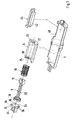
- the adapter element 2 has a cylindrical housing part 4, in which a Sliding sleeve 6 is mounted to be longitudinally displaceable. To better illustrate the im Housing part 4 arranged components is only one cylinder half of the housing part 4th shown.
- the sliding sleeve 6 is also designed as a hollow cylindrical component, in which in turn an adjustment element, hereinafter referred to as inner stamp 8, is guided longitudinally.
- the inner stamp 8 has one at one end Guide piston 10 which is slidably guided in the sliding sleeve 6. On his the other end is a receptacle 12 for a nipple 14 of a Bowden cable 16, provided within a Bowden cable section 18.
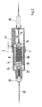
- the Receiving eye 12 for the Bowden cable 16 and one on one end of the Sliding sleeve 6 provided opening 22 are dimensioned so that the Receiving eye 12 in the installed state (see Fig. 2) on the front of the Sliding sleeve 6 supports. This is the case when installing the adapter element 2 Receiving eye 12 with its narrow side through the opening 22 and then rotated by 90 °.
- a Covered element 24 closed, which at the same time a second receiving eye 26 for one second nipple 28 of a received in a second Bowden cable section 30 Bowden cable 32 has.
- this is Cover element 24 attached to the sliding sleeve 6 in the manner of a bayonet catch.
- the circular closure part 34 of the cover element 24 faces radially webs 36 leading to the outside, which in the assembled state on the end face engage the locking sleeve 38 formed locking segments 38.
- the inner stamp 8 is surrounded by a spiral spring 39 which is anode in the sliding sleeve 6 and which is attached to one end of the guide piston 10 of the inner punch 8 and at the other End supported on the inner wall of the sliding sleeve 6.
- a rectangular opening 40 is provided, in which a Stop for the sliding sleeve 6 formed pin 42 of a stop element 44th intervenes.
- the stop element 44 is designed such that it opens 40 closes watertight.
- the first Bowden cable section 18 leads, for example, to the throttle grip of a motorcycle or to the gas pedal of a motor vehicle, while the second Bowden cable section 30 is connected to the throttle valve of an engine.
- the throttle valve is opened via the Bowden cable ropes 16, 32 in proportion to the adjustment path s, the sleeve 6 being displaced within the housing part 4 in the direction of the stop element 44.
- the adjustment path s which in the present case (see FIG. 2) is not necessarily drawn to scale
- the sliding sleeve 6 strikes the pin 42 of the stop element 44 and upon further actuation of the throttle grip, the inner punch becomes counter to the force of the spiral spring 39 8 moved within the sliding sleeve 6. With this adjustment movement there is no further adjustment of the throttle valve; the so-called idle stroke within the sliding sleeve 6 is ended when the coil spring goes to block.
Landscapes
- Engineering & Computer Science (AREA)
- General Engineering & Computer Science (AREA)
- Health & Medical Sciences (AREA)
- Oral & Maxillofacial Surgery (AREA)
- Mechanical Engineering (AREA)
- Control Of Throttle Valves Provided In The Intake System Or In The Exhaust System (AREA)
- Flexible Shafts (AREA)
- Auxiliary Drives, Propulsion Controls, And Safety Devices (AREA)
Abstract
Description
- Fig. 1
- eine Explosionsdarstellung eines im Bowdenzug integrierbaren Adapterelementes und
- Fig. 2
- einen Längsschnitt durch das Adapterelement.
Beim Betätigen des Gasdrehgriffes wird über die Bowdenzugseile 16, 32 proportional zum Verstellweg s die Drosselklappe geöffnet, dabei wird die Hülse 6 innerhalb des Gehäuseteils 4 in Richtung des Anschlagelementes 44 verschoben. Nach dem Durchlaufen des Verstellweges s, der im vorliegenden Fall (siehe Fig. 2) nicht unbedingt maßstabsgerecht dargestellt ist, schlägt die Schiebehülse 6 am Zapfen 42 des Anschlagelementes 44 an und bei einer weiteren Betätigung des Gasdrehgriffes wird entgegen der Kraft der Spiralfeder 39 der Innenstempel 8 innerhalb der Schiebehülse 6 verschoben. Bei dieser Verstellbewegung findet keine weitere Verstellung der Drosselklappe statt; der sogenannte Leerhub innerhalb der Schiebehülse 6 ist beendet, wenn die Spiralfeder auf Block geht.
Claims (3)
- Adapterelement für einen Bowdenzug eines Kraftfahrzeuges, insbesondere zur Begrenzung der Drosselklappenstellung, mit einem Gehäuse (4), in dem eine Schiebehülse (6) angeordnet ist, in der ein Verstellelement (8) entgegen einer Federkraft längsverschieblich aufgenommen ist, wobei das Verstellelement (8) und die Schiebehülse (6) eine Aufnahme (12, 26) zum Einhängen eines Seiles (16, 32) eines Bowdenzug - Abschnittes (18, 30) aufweisen und im bzw. am Gehäuse (4) ein Anschlagelement (44) vorgesehen ist, an dem die Schiebehülse (6) nach Durchlaufen eines Verstellweges anschlägt.
- Vorrichtung nach Anspruch 1, dadurch gekennzeichnet, dass zwischen dem Verstellelement (8) und der Schiebehülse (6) ein Federelement (39) angeordnet ist, das sich an einer Stirnseite der Schiebehülse (6) und am Verstellelement (8) abstützt.
- Vorrichtung nach Anspruch 1 oder 2, dadurch gekennzeichnet, dass im Gehäuse (4) des Adapterelementes (2) eine Öffnung (40) vorgesehen ist, in der das Anschlagelement (44) einsteckbar ist.
Applications Claiming Priority (2)
| Application Number | Priority Date | Filing Date | Title |
|---|---|---|---|
| DE10246502 | 2002-10-04 | ||
| DE2002146502 DE10246502A1 (de) | 2002-10-04 | 2002-10-04 | Adapterelement für einen Bowdenzug eines Kraftfahrzeuges, insbesondere zur Begrenzung der Drosselklappenstellung |
Publications (3)
| Publication Number | Publication Date |
|---|---|
| EP1406023A2 true EP1406023A2 (de) | 2004-04-07 |
| EP1406023A3 EP1406023A3 (de) | 2006-04-12 |
| EP1406023B1 EP1406023B1 (de) | 2007-08-15 |
Family
ID=31984404
Family Applications (1)
| Application Number | Title | Priority Date | Filing Date |
|---|---|---|---|
| EP20030020221 Expired - Lifetime EP1406023B1 (de) | 2002-10-04 | 2003-09-06 | Einstellvorrichtung für einen Bowdenzug, insbesondere für eine Drosselklappenstellung |
Country Status (3)
| Country | Link |
|---|---|
| EP (1) | EP1406023B1 (de) |
| JP (1) | JP2004124944A (de) |
| DE (2) | DE10246502A1 (de) |
Cited By (10)
| Publication number | Priority date | Publication date | Assignee | Title |
|---|---|---|---|---|
| DE102005040861A1 (de) * | 2005-08-29 | 2007-03-01 | Fico Cables, Lda. | Einstellvorrichtung für einen Kabelzug |
| US7469617B2 (en) | 2004-07-22 | 2008-12-30 | Honda Motor Co., Ltd. | Tension compensating assembly for mechanical control cables |
| WO2009059648A1 (en) * | 2007-11-07 | 2009-05-14 | L & P Swiss Holding Company | Support assembly and corresponding seat structure |
| US8840186B2 (en) | 2007-11-07 | 2014-09-23 | L&P Swiss Holding Ag | Support assembly and corresponding seat structure |
| GB2528543A (en) * | 2014-05-13 | 2016-01-27 | Maximilian Vincent Wozniak | Cable coupling system |
| DE102005063551B4 (de) * | 2005-08-29 | 2018-08-30 | Fico Cables, Lda. | Einstellvorrichtung für einen Kabelzug und Kabelzug |
| CN109458070A (zh) * | 2018-12-24 | 2019-03-12 | 东莞雅音电子科技有限公司 | 一种拉索及其拉索缓冲装置 |
| US20240200591A1 (en) * | 2022-12-14 | 2024-06-20 | Gregor Horacek | Bowden Cable Coupling For Releasably Coupling A First Bowden Cable To A Second Bowden Cable |
| US12209684B2 (en) | 2020-05-04 | 2025-01-28 | Aquestia Ltd. | Hydraulically operated valve and systems for use therewith |
| US12650174B2 (en) | 2021-11-10 | 2026-06-09 | Aquestia Ltd | Diaphragm valve incorporating an alarm port |
Families Citing this family (1)
| Publication number | Priority date | Publication date | Assignee | Title |
|---|---|---|---|---|
| US10106216B2 (en) * | 2015-02-13 | 2018-10-23 | Shimano Inc. | Bicycle seatpost assembly with cable connecting device |
Citations (1)
| Publication number | Priority date | Publication date | Assignee | Title |
|---|---|---|---|---|
| DE69213078T2 (de) | 1991-04-26 | 1997-03-27 | Melchor Barcelona Daumal Castellon | Vorrichtung zur automatischen Längenverstellung eines Bowdenzuges |
Family Cites Families (1)
| Publication number | Priority date | Publication date | Assignee | Title |
|---|---|---|---|---|
| US6279415B1 (en) * | 1999-10-27 | 2001-08-28 | Visteon Global Tech., Inc. | Method and apparatus for providing tension within a cable |
-
2002
- 2002-10-04 DE DE2002146502 patent/DE10246502A1/de not_active Ceased
-
2003
- 2003-09-06 DE DE50307940T patent/DE50307940D1/de not_active Expired - Lifetime
- 2003-09-06 EP EP20030020221 patent/EP1406023B1/de not_active Expired - Lifetime
- 2003-10-01 JP JP2003343446A patent/JP2004124944A/ja active Pending
Patent Citations (1)
| Publication number | Priority date | Publication date | Assignee | Title |
|---|---|---|---|---|
| DE69213078T2 (de) | 1991-04-26 | 1997-03-27 | Melchor Barcelona Daumal Castellon | Vorrichtung zur automatischen Längenverstellung eines Bowdenzuges |
Cited By (20)
| Publication number | Priority date | Publication date | Assignee | Title |
|---|---|---|---|---|
| US7469617B2 (en) | 2004-07-22 | 2008-12-30 | Honda Motor Co., Ltd. | Tension compensating assembly for mechanical control cables |
| CN100447436C (zh) * | 2004-07-22 | 2008-12-31 | 本田技研工业株式会社 | 用于机械控制缆线的张力补偿组件 |
| US7640825B2 (en) * | 2004-07-22 | 2010-01-05 | Honda Motor Co., Ltd | Tension compensating assembly for mechanical control cables |
| CN101311562B (zh) * | 2004-07-22 | 2010-10-06 | 本田技研工业株式会社 | 用于机械控制缆线的张力补偿组件 |
| DE102005040861B4 (de) * | 2005-08-29 | 2011-03-24 | Fico Cables, Lda. | Einstellvorrichtung für einen Kabelzug und Kabelzug |
| WO2007025590A1 (en) * | 2005-08-29 | 2007-03-08 | Fico Cables, Lda | Adjustment device for a control cable |
| DE102005063551B4 (de) * | 2005-08-29 | 2018-08-30 | Fico Cables, Lda. | Einstellvorrichtung für einen Kabelzug und Kabelzug |
| DE102005040861A1 (de) * | 2005-08-29 | 2007-03-01 | Fico Cables, Lda. | Einstellvorrichtung für einen Kabelzug |
| EP2380461A1 (de) * | 2007-11-07 | 2011-10-26 | L & P Swiss Holding AG | Unterstützungsanordnung und entsprechende Sitzstruktur |
| JP2011502595A (ja) * | 2007-11-07 | 2011-01-27 | エル アンド ピー スイス ホールディング アーゲー | 支持アセンブリ及び対応する座席構造体 |
| US7841662B2 (en) | 2007-11-07 | 2010-11-30 | L&P Swiss Holding Company | Support assembly and corresponding seat structure |
| US8840186B2 (en) | 2007-11-07 | 2014-09-23 | L&P Swiss Holding Ag | Support assembly and corresponding seat structure |
| CN102065729B (zh) * | 2007-11-07 | 2014-11-26 | L&P瑞士持有股份有限公司 | 支撑组合件和对应的座椅结构 |
| WO2009059648A1 (en) * | 2007-11-07 | 2009-05-14 | L & P Swiss Holding Company | Support assembly and corresponding seat structure |
| GB2528543A (en) * | 2014-05-13 | 2016-01-27 | Maximilian Vincent Wozniak | Cable coupling system |
| CN109458070A (zh) * | 2018-12-24 | 2019-03-12 | 东莞雅音电子科技有限公司 | 一种拉索及其拉索缓冲装置 |
| US12209684B2 (en) | 2020-05-04 | 2025-01-28 | Aquestia Ltd. | Hydraulically operated valve and systems for use therewith |
| US12650174B2 (en) | 2021-11-10 | 2026-06-09 | Aquestia Ltd | Diaphragm valve incorporating an alarm port |
| US20240200591A1 (en) * | 2022-12-14 | 2024-06-20 | Gregor Horacek | Bowden Cable Coupling For Releasably Coupling A First Bowden Cable To A Second Bowden Cable |
| US12331777B2 (en) * | 2022-12-14 | 2025-06-17 | Gkf Invest Gmbh | Bowden cable coupling for releasably coupling a first Bowden cable to a second Bowden cable |
Also Published As
| Publication number | Publication date |
|---|---|
| DE50307940D1 (de) | 2007-09-27 |
| JP2004124944A (ja) | 2004-04-22 |
| DE10246502A1 (de) | 2004-04-22 |
| EP1406023A3 (de) | 2006-04-12 |
| EP1406023B1 (de) | 2007-08-15 |
Similar Documents
| Publication | Publication Date | Title |
|---|---|---|
| DE19548139C2 (de) | Gasfeder mit einstellbarer Endposition | |
| DE19632099C2 (de) | Luftsteuerventil | |
| DE3405053A1 (de) | Solenoid-ventil in patronenbauweise mit ueberlagerter handsteuerung | |
| DE69210194T2 (de) | Selbstbegrenzungs-Slavekolben | |
| EP1406023B1 (de) | Einstellvorrichtung für einen Bowdenzug, insbesondere für eine Drosselklappenstellung | |
| DE102016209824A1 (de) | Dämpfer | |
| EP2134563A1 (de) | Betätigungsvorrichtung für eine abdeckung einer karosserieöffnung eines kraftfahrzeugs | |
| DE102015203378A1 (de) | Verbrennungskraftmaschine mit einstellbarem variablen Verdichtungsverhältnis und einem Schaltmodul | |
| EP1244187A1 (de) | Hydraulisches Pressgerät und Verfahren zum Betreiben desselben | |
| EP1591856B1 (de) | Druckregelventil | |
| EP0894215B1 (de) | Ventil für flüssigkeiten | |
| DE102016209826A1 (de) | Dämpfer | |
| DE2134093C3 (de) | Druckreduzierventil | |
| DE60102176T2 (de) | Einbauventil | |
| DE102006025965B4 (de) | Gaszylinder-Ventilanordnung | |
| DE3444855C1 (de) | Auch bei unter Druck stehendem Stecker kuppelbare Rohrabreisskupplung fuer insbes. Hydraulikleitungen | |
| EP1048040B1 (de) | Vorrichtung zur nothandbetätigung bei schaltmagneten | |
| DE102017205772A1 (de) | Kugelventil | |
| WO2017186449A1 (de) | Elektromagnetventil sowie betriebsverfahren | |
| DE2855812C2 (de) | ||
| DE4407447A1 (de) | Voreinstellbares Regulierventil | |
| DE10030699C2 (de) | Voreinstellbares Einbauventil | |
| DE60109108T2 (de) | Abgasrückführventil für eine Brennkraftmaschine | |
| DE2361591A1 (de) | Schieberventil zur steuerung des arbeitsdrucks eines arbeitsmediums | |
| DE102010023574A1 (de) | Eckventil |
Legal Events
| Date | Code | Title | Description |
|---|---|---|---|
| PUAI | Public reference made under article 153(3) epc to a published international application that has entered the european phase |
Free format text: ORIGINAL CODE: 0009012 |
|
| AK | Designated contracting states |
Kind code of ref document: A2 Designated state(s): AT BE BG CH CY CZ DE DK EE ES FI FR GB GR HU IE IT LI LU MC NL PT RO SE SI SK TR |
|
| AX | Request for extension of the european patent |
Extension state: AL LT LV MK |
|
| PUAL | Search report despatched |
Free format text: ORIGINAL CODE: 0009013 |
|
| AK | Designated contracting states |
Kind code of ref document: A3 Designated state(s): AT BE BG CH CY CZ DE DK EE ES FI FR GB GR HU IE IT LI LU MC NL PT RO SE SI SK TR |
|
| AX | Request for extension of the european patent |
Extension state: AL LT LV MK |
|
| 17P | Request for examination filed |
Effective date: 20061012 |
|
| AKX | Designation fees paid |
Designated state(s): DE FR GB IT |
|
| GRAP | Despatch of communication of intention to grant a patent |
Free format text: ORIGINAL CODE: EPIDOSNIGR1 |
|
| GRAS | Grant fee paid |
Free format text: ORIGINAL CODE: EPIDOSNIGR3 |
|
| GRAA | (expected) grant |
Free format text: ORIGINAL CODE: 0009210 |
|
| AK | Designated contracting states |
Kind code of ref document: B1 Designated state(s): DE FR GB IT |
|
| REG | Reference to a national code |
Ref country code: GB Ref legal event code: FG4D Free format text: NOT ENGLISH |
|
| REF | Corresponds to: |
Ref document number: 50307940 Country of ref document: DE Date of ref document: 20070927 Kind code of ref document: P |
|
| GBT | Gb: translation of ep patent filed (gb section 77(6)(a)/1977) |
Effective date: 20071115 |
|
| ET | Fr: translation filed | ||
| PLBE | No opposition filed within time limit |
Free format text: ORIGINAL CODE: 0009261 |
|
| STAA | Information on the status of an ep patent application or granted ep patent |
Free format text: STATUS: NO OPPOSITION FILED WITHIN TIME LIMIT |
|
| 26N | No opposition filed |
Effective date: 20080516 |
|
| REG | Reference to a national code |
Ref country code: FR Ref legal event code: TP |
|
| REG | Reference to a national code |
Ref country code: FR Ref legal event code: CD |
|
| PGFP | Annual fee paid to national office [announced via postgrant information from national office to epo] |
Ref country code: FR Payment date: 20101005 Year of fee payment: 8 Ref country code: IT Payment date: 20100923 Year of fee payment: 8 |
|
| PGFP | Annual fee paid to national office [announced via postgrant information from national office to epo] |
Ref country code: GB Payment date: 20100921 Year of fee payment: 8 |
|
| REG | Reference to a national code |
Ref country code: FR Ref legal event code: TP |
|
| REG | Reference to a national code |
Ref country code: GB Ref legal event code: 732E Free format text: REGISTERED BETWEEN 20110310 AND 20110316 |
|
| REG | Reference to a national code |
Ref country code: GB Ref legal event code: 732E Free format text: REGISTERED BETWEEN 20110331 AND 20110406 |
|
| GBPC | Gb: european patent ceased through non-payment of renewal fee |
Effective date: 20110906 |
|
| PG25 | Lapsed in a contracting state [announced via postgrant information from national office to epo] |
Ref country code: IT Free format text: LAPSE BECAUSE OF NON-PAYMENT OF DUE FEES Effective date: 20110906 |
|
| REG | Reference to a national code |
Ref country code: FR Ref legal event code: ST Effective date: 20120531 |
|
| PG25 | Lapsed in a contracting state [announced via postgrant information from national office to epo] |
Ref country code: FR Free format text: LAPSE BECAUSE OF NON-PAYMENT OF DUE FEES Effective date: 20110930 Ref country code: GB Free format text: LAPSE BECAUSE OF NON-PAYMENT OF DUE FEES Effective date: 20110906 |
|
| PGFP | Annual fee paid to national office [announced via postgrant information from national office to epo] |
Ref country code: DE Payment date: 20120816 Year of fee payment: 10 |
|
| REG | Reference to a national code |
Ref country code: DE Ref legal event code: R119 Ref document number: 50307940 Country of ref document: DE Effective date: 20140401 |
|
| PG25 | Lapsed in a contracting state [announced via postgrant information from national office to epo] |
Ref country code: DE Free format text: LAPSE BECAUSE OF NON-PAYMENT OF DUE FEES Effective date: 20140401 |