EP1405965A1 - Modular system for parking and storing bicycles - Google Patents
Modular system for parking and storing bicycles Download PDFInfo
- Publication number
- EP1405965A1 EP1405965A1 EP20020730312 EP02730312A EP1405965A1 EP 1405965 A1 EP1405965 A1 EP 1405965A1 EP 20020730312 EP20020730312 EP 20020730312 EP 02730312 A EP02730312 A EP 02730312A EP 1405965 A1 EP1405965 A1 EP 1405965A1
- Authority
- EP
- European Patent Office
- Prior art keywords
- parking
- bicycle
- bicycles
- storage
- modular system
- Prior art date
- Legal status (The legal status is an assumption and is not a legal conclusion. Google has not performed a legal analysis and makes no representation as to the accuracy of the status listed.)
- Granted
Links
- 238000004873 anchoring Methods 0.000 claims description 2
- 230000015572 biosynthetic process Effects 0.000 description 1
- 230000008878 coupling Effects 0.000 description 1
- 238000010168 coupling process Methods 0.000 description 1
- 238000005859 coupling reaction Methods 0.000 description 1
- 238000009434 installation Methods 0.000 description 1
- 230000007774 longterm Effects 0.000 description 1
- 239000002184 metal Substances 0.000 description 1
- 239000007769 metal material Substances 0.000 description 1
- 238000005192 partition Methods 0.000 description 1
Images



Classifications
-
- B—PERFORMING OPERATIONS; TRANSPORTING
- B62—LAND VEHICLES FOR TRAVELLING OTHERWISE THAN ON RAILS
- B62H—CYCLE STANDS; SUPPORTS OR HOLDERS FOR PARKING OR STORING CYCLES; APPLIANCES PREVENTING OR INDICATING UNAUTHORIZED USE OR THEFT OF CYCLES; LOCKS INTEGRAL WITH CYCLES; DEVICES FOR LEARNING TO RIDE CYCLES
- B62H3/00—Separate supports or holders for parking or storing cycles
- B62H3/04—Separate supports or holders for parking or storing cycles involving forked supports of brackets for holding a wheel
-
- B—PERFORMING OPERATIONS; TRANSPORTING
- B62—LAND VEHICLES FOR TRAVELLING OTHERWISE THAN ON RAILS
- B62H—CYCLE STANDS; SUPPORTS OR HOLDERS FOR PARKING OR STORING CYCLES; APPLIANCES PREVENTING OR INDICATING UNAUTHORIZED USE OR THEFT OF CYCLES; LOCKS INTEGRAL WITH CYCLES; DEVICES FOR LEARNING TO RIDE CYCLES
- B62H3/00—Separate supports or holders for parking or storing cycles
- B62H3/08—Separate supports or holders for parking or storing cycles involving recesses or channelled rails for embracing the bottom part of a wheel
-
- E—FIXED CONSTRUCTIONS
- E04—BUILDING
- E04H—BUILDINGS OR LIKE STRUCTURES FOR PARTICULAR PURPOSES; SWIMMING OR SPLASH BATHS OR POOLS; MASTS; FENCING; TENTS OR CANOPIES, IN GENERAL
- E04H6/00—Buildings for parking cars, rolling-stock, aircraft, vessels or like vehicles, e.g. garages
- E04H6/005—Garages for vehicles on two wheels
Definitions
- the object of the present patent is a modular system for parking-storing bicycles and more specifically a container or modular locker provided with suitable special means for parking or storing a bicycle inside, in an absolutely secure and reliable fashion, said container or locker being apt for coupling to other identical ones to form a battery consisting of an indefinite number of them.
- the present patent sets out to overcome all the drawbacks of already known systems, providing a new bicycle parking-storage system that permits optimum utilisation of space, which offers integrated protection for bicycles against theft, vandalism and the elements, both in public and semi-public places, which is simple and convenient to use and maintain, even by physically frail persons, and which provides high flexibility of installation and use as urban furniture. It is therefore worthy of the registration protection being applied for.
- the system in question is essentially characterised in that it is built of modules each formed of a generally triangular-shaped base on which is anchored a strut or upright that, like the base, acts as a support for horizontal or upward sloping runners along which the wheels of the bicycle run when it is pushed up to occupy the inclined position in which it is to be parked or stored, said base also being provided with elements, on other struts or uprights, that take up and guide the pedals, or restrict their movement, when the bicycle is pushed along the runners, until they reach an end position in which one of them is situated above the axis of rotation and the other below.
- said elements located on either side of the bicycle wheel guide runners, each consist of bars or plates, anchored vertically on the base and provided with a double elbow, which are moved in respective of one other and arranged in such a way that their respective elbows are also opposite each other, so that these elbows determine the spaces in which the pedals have to be situated, in a pre-set position, when the bicycle is put into the module.
- the afore-mentioned bars are arranged parallel to one other and are each fitted with horizontal appendices determining the place in which the pedals have to be located, in a pre-set position, when the bicycle is put into the module.
- the aforesaid vertical bars or plates each have slip bands which follow approximately the line of movement of the axis of rotation of the pedals and force them to slide, according to their natural movement and utilising the bicycle input thrust, until they reach the required positions, defined by the above-mentioned elbows.
- one of the afore-mentioned slip bands is composed of a dished downward oriented guide plate and the other slip band is made up of a slightly dished guide plate of generally horizontal orientation and a second basically C-shaped plate, which is jointed to one of the ends of the first plate and is able to turn back and forth between a generally vertical, home position and another slightly set-back position, in which it enters into contact with a spring or thrust element that returns it to its home position so that it may, when required, receive one of the pedals and force it to move downwards and remain behind the opposite one, in the direction of bicycle advance into the module.
- the guide runners include at least one upward sloping section, up which one of the wheels of the bicycle runs when it enters the module, and a section fixed horizontally to the base and situated in line with the former, on which the other wheel of the bicycle rests in the end parking or storage position.
- the upward sloping guide runner section is topped at its upper end by another appreciably horizontal or slightly downward sloping section on which the wheel that has previously ascended the aforesaid inclined section rests in the end bicycle parking position.
- the runner section fixed to the base is situated in a position adjacent to the lower end of the upward sloping section of runner.
- the aforesaid runner section fixed to the base has pronounced stepping that assists the anchoring of the bicycle wheel onto this section.
- the afore-mentioned section of runner attached to the base is jointed to this at its front end, which enables it to turn from the horizontal position, in which one wheel is housed, and the inclined position, in which it acts as a continuation to the section of upward sloping runner.
- the section of runner jointed to the base has an adjacent lever or pedal which enables the user to move this section of runner between its two possible positions.
- the section of upward sloping runner has a slight bend or elbow at the top end in the direction of the longitudinal axis of the module to leave both wheels of the bicycle facing each other.
- this section of upward sloping runner has a slight bend or elbow at the top end in the direction of the longitudinal axis of the module to balance the position of the pedals on the axis of the module.
- the modules include one or more suitably arranged yokes for securing one or both wheels of the bicycle.
- the modules may be juxtaposed to one another and, when they are so, share their respective elbow bars, while the slip bands of adjoining modules are arranged suitably to direct the pedals of each bicycle to the spaces provided.
- the modules are each housed in containers or lockers which, being juxtaposed and suitably attached to one another, form linear structures, if they are joined in successively opposed orientations, or circular ones, if they are joined with the bases coinciding at their vertices, in the former case with the access doors to the modules having the structure either at the front or the back.
- the pedal slip bands and the bicycle wheel guide runners are arranged in successively inverted positions in order that the bicycles may be parked successively also in opposing directions and with opposite inclinations when it comes to juxtaposing the containers or lockers and making them accessible from the front or back of the same structure.
- the module according to the system that is the object of the invention is made up of a generally triangular-shaped base, the shape and area of which indicate approximately the space occupied by this module, on which a strut or upright (3) is anchored vertically so as to act as a support for a runner (4), of plastic or metallic material, which takes on a general obtuse-angled shape with uneven sides, the smaller of which rests in a slightly backward sloping position on the aforesaid strut or upright 3, while the longer side, which is connected to the smaller one by way of a wide-angled elbow, extends in a slanting direction until reaching the base 1.
- Fixed on this base in a position adjacent to the end of the above-mentioned runner 4, there is another short straight runner (5), arranged parallel to the aforesaid runner 4.
- struts or uprights (8) are also anchored at the base 1 in suitable positions to act as a support, on both sides of runners 4 and 5, for both slip bands (9), which extend at different heights from the elbows of the above-mentioned bars or plates 6 and which are made up, in the case of one of them (9a) of a dished plate with a downward orientation, and of the other (9b) of a slightly dished plate with a generally horizontal orientation, which is provided at the end with another jointed plate (9c), basically of a very open C shape, which slopes downwards and is able to turn between a generally vertical home position and another slightly set-back position in which it comes into contact with a spring or thrust element (10) that returns it to its generally vertical home position.
- slip bands (9) which extend at different heights from the elbows of the above-mentioned bars or plates 6 and which are made up, in the case of one of them (9a) of a dished plate with a downward orientation, and of the other (9b) of a
- the slip band that occupies the first place presents the C-shaped plate 9c situated at the front and the dished plate 9a situated at the back;
- the slip band occupying the second place presents the C-shaped plate 9c situated at the back and the dished plate 9a situated at the front;
- the slip band occupying the third place takes up the position of the first one again, and so on and so forth.
- the runners 4 and 5 and the input opening to each module are arranged in successively inverted positions, i.e. between the slip bands that occupy first and second places - corresponding to the first module assembled ⁇ runner 5 and the input opening are situated at the rear of the structure and runner 4 is angled from back to front; between the slip bands occupying the third and fourth places - corresponding to the third module assembled - both runners and the input opening occupy the same positions again as those of the first module, and so on and so forth.
- the bicycle is pushed so that its front wheel moves along runner 5, in which it has to be located, and its rear wheel runs up the sloping runner 4, passes over its elbow and ends up on the shorter side of this runner, inclined backwards slightly for securer fastening.
- the function of the slip bands is, therefore, to make sure that, in the bicycle rest position, one of the two pedals is always above the axis of rotation and the other below. In this way, the elbow spaces not occupied by the pedals are available for the pedals of the bicycle that is located in the adjoining position.
- a runner 4 which takes on a general obtuse-angle form and which is located with one of its sides in a position inclined backwards slightly and opposite the strut or upright 11, and the other side facing towards the base 1, at the front middle part of which there is another short straight runner 5 attached of the same characteristics as the runner 4 and located in line with it.
- This runner 5 may be jointed to the base 1, at its front end, by means of a support that the user may operate with a lever (13) or another device to turn the runner 5 back and forth between its horizontal position and another inclined position in which it acts as a continuation of runner 4.
- the bicycle 2 is pushed backwards so that one of its wheels runs first along runner 5, set previously in its inclined position, and then ascends the front side of runner 4 until reaching its rear side, on which it will rest firmly, in an inclined position, which is when the other wheel of the bicycle will be engaged and supported on runner 5 anchored to the base, once this runner 5 has returned to its horizontal position.
- the pedals are positioned in such a way that they occupy the space permitted for them by the vertical bars 6, one of them below its double elbow and the above.
- Runner 4 also has the same approximate obtuse-angled form with uneven sides, though with the shorter side oriented vertically. On this shorter side, to which the yoke 12a is attached, this runner is fixed to the front of the strut or upright 11, while the longer side is oriented diagonally towards the base 1, in line with the runner 5.
- This runner is provided with pronounced inverted acute-angle stepping which means that the runner is divided into three sections: a front section sloping upwards from back to front, a middle section sloping downwards from back to front, and a horizontal last section.
- the double elbow of the bars 6 is more pronounced than in the specimen embodiment in Figures 4 and 5, so that the middle area of these bars has a steeper inclination than in the previous specimen embodiment.
- a second yoke (12b), attached to the base in line with runner 5, is intended to secure the wheel housed in this runner.
- bicycle 2 is pushed backwards so that its rear wheel is raised up to runner 4, along which it moves until it is clamped by the yoke 12a. At that moment, after moving along the runner 5, the front wheel reaches the last horizontal section of same and is firmly secured in it through being unable to advance over the step established in the runner and to move sideways due to the action of the yoke 12b.
- the arrangement of the vertical bars 6 and their elbows limits the space that the pedals may occupy when parking the bicycle in the module: one above and the other below the axis of rotation.
- the specimen embodiment represented in Figure 8 is practically the same as that in Figures 6 and 7, from which it only differs in that the bars 6 are arranged parallel and each have, approximately halfway up, small double right-angle elbows determining the formation of short horizontal sections to each of which approximately U-shaped appendices (14) are horizontally attached, oriented horizontally towards the strut or upright 11, which limit the space that may be occupied by the pedals of the bicycle 2 in the usual position, in which one of them is above the axis or rotation and the other below.
- the modules according to any of the different specimen embodiments of the system in question may be juxtaposed to one another or be each housed in containers or lockers which, when suitably juxtaposed or joined together, form linear structures (15), like the one represented in Figure 9, or circular structures like the one illustrated in Figure 10.
- linear structures like the one represented in Figure 9, or circular structures like the one illustrated in Figure 10.
- the arrangement of the bars and their elbows and appendices described in relation to Figure 8, applied to any specimen embodiment permits the juxtaposition of modules sharing the rear vertex so as to form the circle characteristic of the structure.
- the modules of each structure have their respective access doors (17), which, in the case of a linear structure, may be situated either at the front or back of the structure in order to permit access to them according to the parking or storage position of the bicycle.
- modules might include hooks, anchors, chains, anti-theft devices or any other fastening elements in replacement or in addition to the yokes 12a and 12b.
Landscapes
- Engineering & Computer Science (AREA)
- Architecture (AREA)
- Mechanical Engineering (AREA)
- Civil Engineering (AREA)
- Structural Engineering (AREA)
- Vehicle Step Arrangements And Article Storage (AREA)
- Motorcycle And Bicycle Frame (AREA)
- Warehouses Or Storage Devices (AREA)
- Steering Devices For Bicycles And Motorcycles (AREA)
- Assembled Shelves (AREA)
Abstract
Description
- The object of the present patent is a modular system for parking-storing bicycles and more specifically a container or modular locker provided with suitable special means for parking or storing a bicycle inside, in an absolutely secure and reliable fashion, said container or locker being apt for coupling to other identical ones to form a battery consisting of an indefinite number of them.
- There already exist systems for parking bicycles.
- Most of them consist of more or less complete and generally metal devices, to which the bicycles are secured by means of chains or anti-theft devices. These systems offer a certain protection against overall theft but very little against theft of parts, vandalism and the elements.
- Other "container" or "locker" type systems in use basically consist of a box fixed to the ground or to a wall in which the bicycle is enclosed. These systems have the drawback that they are usually expensive to build and, what is more, require a lot of space for each bicycle stored, which impedes their widespread use as an item of urban furniture.
- Finally, there are also systems based on hanging the bicycle to keep it in a vertical position or with one or two of its components folded. These systems are usually confined either to long-term storage or indoors since they are inconvenient or even awkward to use for many people.
- The present patent sets out to overcome all the drawbacks of already known systems, providing a new bicycle parking-storage system that permits optimum utilisation of space, which offers integrated protection for bicycles against theft, vandalism and the elements, both in public and semi-public places, which is simple and convenient to use and maintain, even by physically frail persons, and which provides high flexibility of installation and use as urban furniture. It is therefore worthy of the registration protection being applied for.
- The system in question is essentially characterised in that it is built of modules each formed of a generally triangular-shaped base on which is anchored a strut or upright that, like the base, acts as a support for horizontal or upward sloping runners along which the wheels of the bicycle run when it is pushed up to occupy the inclined position in which it is to be parked or stored, said base also being provided with elements, on other struts or uprights, that take up and guide the pedals, or restrict their movement, when the bicycle is pushed along the runners, until they reach an end position in which one of them is situated above the axis of rotation and the other below.
- According to another feature of the invention, said elements, located on either side of the bicycle wheel guide runners, each consist of bars or plates, anchored vertically on the base and provided with a double elbow, which are moved in respective of one other and arranged in such a way that their respective elbows are also opposite each other, so that these elbows determine the spaces in which the pedals have to be situated, in a pre-set position, when the bicycle is put into the module.
- According to a further feature of the invention, the afore-mentioned bars are arranged parallel to one other and are each fitted with horizontal appendices determining the place in which the pedals have to be located, in a pre-set position, when the bicycle is put into the module.
- According to another feature of the invention, the aforesaid vertical bars or plates each have slip bands which follow approximately the line of movement of the axis of rotation of the pedals and force them to slide, according to their natural movement and utilising the bicycle input thrust, until they reach the required positions, defined by the above-mentioned elbows.
- According to a further feature of the invention, one of the afore-mentioned slip bands is composed of a dished downward oriented guide plate and the other slip band is made up of a slightly dished guide plate of generally horizontal orientation and a second basically C-shaped plate, which is jointed to one of the ends of the first plate and is able to turn back and forth between a generally vertical, home position and another slightly set-back position, in which it enters into contact with a spring or thrust element that returns it to its home position so that it may, when required, receive one of the pedals and force it to move downwards and remain behind the opposite one, in the direction of bicycle advance into the module.
- According to another feature of the invention, the guide runners include at least one upward sloping section, up which one of the wheels of the bicycle runs when it enters the module, and a section fixed horizontally to the base and situated in line with the former, on which the other wheel of the bicycle rests in the end parking or storage position.
- According to another feature of the invention, the upward sloping guide runner section is topped at its upper end by another appreciably horizontal or slightly downward sloping section on which the wheel that has previously ascended the aforesaid inclined section rests in the end bicycle parking position.
- According to another feature of the invention, the runner section fixed to the base is situated in a position adjacent to the lower end of the upward sloping section of runner.
- According to another feature of the invention, the aforesaid runner section fixed to the base has pronounced stepping that assists the anchoring of the bicycle wheel onto this section.
- According to another feature of the invention, the afore-mentioned section of runner attached to the base is jointed to this at its front end, which enables it to turn from the horizontal position, in which one wheel is housed, and the inclined position, in which it acts as a continuation to the section of upward sloping runner.
- According to another feature of the invention, the section of runner jointed to the base has an adjacent lever or pedal which enables the user to move this section of runner between its two possible positions.
- According to another feature of the invention, the section of upward sloping runner has a slight bend or elbow at the top end in the direction of the longitudinal axis of the module to leave both wheels of the bicycle facing each other.
- According to another feature of the invention, this section of upward sloping runner has a slight bend or elbow at the top end in the direction of the longitudinal axis of the module to balance the position of the pedals on the axis of the module.
- According to another feature of the invention, the modules include one or more suitably arranged yokes for securing one or both wheels of the bicycle.
- According to another feature of the invention, the modules, whether or not provided with individual covers, may be juxtaposed to one another and, when they are so, share their respective elbow bars, while the slip bands of adjoining modules are arranged suitably to direct the pedals of each bicycle to the spaces provided.
- According to another feature of the invention, the modules are each housed in containers or lockers which, being juxtaposed and suitably attached to one another, form linear structures, if they are joined in successively opposed orientations, or circular ones, if they are joined with the bases coinciding at their vertices, in the former case with the access doors to the modules having the structure either at the front or the back.
- According to a final feature of the system that is the object of the invention, in the assembly formed by means of the linear juxtaposition of a number of modules, the pedal slip bands and the bicycle wheel guide runners are arranged in successively inverted positions in order that the bicycles may be parked successively also in opposing directions and with opposite inclinations when it comes to juxtaposing the containers or lockers and making them accessible from the front or back of the same structure.
- The features of the system in question are described below with reference to the figures in the adjoining sheets of drawings illustrating the different modes of embodiment of the invention put forward by way of example and not on a restrictive basis, so that their possible versions, as long as they are merely incidental and do not lead to a different new industrial result, should be included within the scope of protection stemming from the registration being applied for.
- Figure 1 shows a perspective view of a module referring to a first example of embodiment of the system according to the invention, withdrawn from the container or locker that acts as its housing and provided with the means necessary for parking-storage of a bicycle and to co-operate, furthermore, in the parking-storage of another two bicycles each in respective analogous adjoining modules.
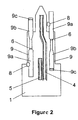
- Figure 2 shows a plan view of the module illustrated in Figure 1.
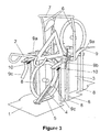
- Figure 3 shows a perspective view, similar to that of Figure 1, illustrating two assembled modules designed for the parking-storage of two bicycles and to co-operate in the parking-storage of another two, with one of them already installed or parked in one of the two modules.
- Figure 4 shows a view, similar to that of Figure 1, illustrating a module referring to a second example of embodiment of the system according to the invention.
- Figure 5 shows a perspective view of the same module illustrated in Figure 4 with a bicycle installed or parked in it.
- Figure 6 shows a view, similar to that of Figure 1, illustrating a module referring to a third example of embodiment of the system according to the invention.
- Figure 7 shows a perspective view of the same module illustrated in Figure 6 with a bicycle installed or parked in it.
- Figure 8 shows a perspective view of a module referring to a fourth specimen embodiment of the system according to the invention., also withdrawn from the container or locker in which it is normally housed and without the bicycle being installed or fitted in it.
- Figure 9 shows a perspective view of a rectangular plan structure formed by joining or juxtaposing different containers or lockers, one of which is partly open so that we may see the interior arrangement of a module like that illustrated in Figure 1.
- Figure 10 represents a perspective view of another circular plan structure formed by joining or juxtaposing different containers or lockers, one of which is partly open so that we may see the interior arrangement of various modules, also juxtaposed, without interior partitions, of the type illustrated in Figure 8, each with a bicycle installed or fitted in it
-
- In these figures the same or equivalent parts or elements are designated with the same reference numbers of signs.
- In the specimen embodiment illustrated in Figures 1, 2 and 3, the module according to the system that is the object of the invention is made up of a generally triangular-shaped base, the shape and area of which indicate approximately the space occupied by this module, on which a strut or upright (3) is anchored vertically so as to act as a support for a runner (4), of plastic or metallic material, which takes on a general obtuse-angled shape with uneven sides, the smaller of which rests in a slightly backward sloping position on the aforesaid strut or upright 3, while the longer side, which is connected to the smaller one by way of a wide-angled elbow, extends in a slanting direction until reaching the
base 1. Fixed on this base, in a position adjacent to the end of the above-mentionedrunner 4, there is another short straight runner (5), arranged parallel to theaforesaid runner 4. - Also anchored to
base 1, on both sides of therunner 4, there are vertical bars or plates (6) which have a double elbow in the middle, said bars or plates being displaced in respect of each other and arranged so that their respective elbows are also opposite each other, while these vertical bars orplates 6 of all the assembled modules may be joined at their respective ends by means of a tie rod (7) connecting them. - Other struts or uprights (8) are also anchored at the
base 1 in suitable positions to act as a support, on both sides ofrunners plates 6 and which are made up, in the case of one of them (9a) of a dished plate with a downward orientation, and of the other (9b) of a slightly dished plate with a generally horizontal orientation, which is provided at the end with another jointed plate (9c), basically of a very open C shape, which slopes downwards and is able to turn between a generally vertical home position and another slightly set-back position in which it comes into contact with a spring or thrust element (10) that returns it to its generally vertical home position. - In the assembly formed through the linear juxtaposition of a number of modules, as illustrated in Figures 1 and 2 - a juxtaposition which is represented for two modules in Figure 3 - the vertical bars are shared and the slip bands are arranged in successively inverted positions, so that the
slip band 9plate 9b of a module is situated after theslip band 9plate 9a of the adjacent module, forming a continuous whole with the form as shown in the figures. In this way, the slip band that occupies the first place presents the C-shaped plate 9c situated at the front and thedished plate 9a situated at the back; the slip band occupying the second place presents the C-shaped plate 9c situated at the back and thedished plate 9a situated at the front; the slip band occupying the third place takes up the position of the first one again, and so on and so forth. - Accordingly, in this linear succession of modules the
runners runner 5 and the input opening are situated at the rear of the structure andrunner 4 is angled from back to front; between the slip bands occupying the third and fourth places - corresponding to the third module assembled - both runners and the input opening occupy the same positions again as those of the first module, and so on and so forth. - This reversal of positions in the adjoining modules assembled in a line and in their components enables bicycles to be parked or stored in opposite directions - i.e. facing first the front and then the back successively - and with opposing inclinations as well, which means that better use is made of space.
- In this specimen embodiment of the system the bicycle is pushed so that its front wheel moves along
runner 5, in which it has to be located, and its rear wheel runs up the slopingrunner 4, passes over its elbow and ends up on the shorter side of this runner, inclined backwards slightly for securer fastening. - During the movement of the bicycle to set it in its end parking or storage position, depending on the angle of the pedals, two things may happen: one of them may come up against the
plate 9a of one of the slip bands or that the other may do so with the C-shaped plate 9c of the other slip band. In the former case, taking advantage of the backward thrust of the bicycle and the ability of the pedal to turn backwards freely as well, thatplate 9a directs the pedal downwards so that it runs below the above-mentionedplate 9a; in the latter case, the C-shaped plate 9c receives and guides the respective pedal - in those positions in which theother pedal 9a would be at an angle that would lock the movement of the assembly - moving it back so as to get past these positions, prevent locking and finally pass over theplate 9b. - The function of the slip bands is, therefore, to make sure that, in the bicycle rest position, one of the two pedals is always above the axis of rotation and the other below. In this way, the elbow spaces not occupied by the pedals are available for the pedals of the bicycle that is located in the adjoining position.
- In the specimen embodiment illustrated in Figures 4 and 5, at its
rear vertex base 1 has a strut or upright (11) anchored vertically with a special purpose yoke (12a) attached to the front for securing the wheel of the bicycle (2) housed in the upper section of the runner. - At a certain distance from the strut or upright 11 and on both sides of same the
vertical bars 6 already described, with a double obtuse angle and without the slip bands described in relation to the previous specimen embodiment, are anchored to the base. - Between the strut or upright 11 and the
bars 6base 1 is also provided with another strut or upright 3 to which arunner 4 is attached which takes on a general obtuse-angle form and which is located with one of its sides in a position inclined backwards slightly and opposite the strut or upright 11, and the other side facing towards thebase 1, at the front middle part of which there is another shortstraight runner 5 attached of the same characteristics as therunner 4 and located in line with it. - This
runner 5 may be jointed to thebase 1, at its front end, by means of a support that the user may operate with a lever (13) or another device to turn therunner 5 back and forth between its horizontal position and another inclined position in which it acts as a continuation ofrunner 4. - In this specimen embodiment of the system the
bicycle 2 is pushed backwards so that one of its wheels runs first alongrunner 5, set previously in its inclined position, and then ascends the front side ofrunner 4 until reaching its rear side, on which it will rest firmly, in an inclined position, which is when the other wheel of the bicycle will be engaged and supported onrunner 5 anchored to the base, once thisrunner 5 has returned to its horizontal position. During the movement of the bicycle until reaching that end position, the pedals are positioned in such a way that they occupy the space permitted for them by thevertical bars 6, one of them below its double elbow and the above. - The specimen embodiment of the system illustrated in Figures 6 and 7 has the same form as that shown in Figures 4 and 5 and only differs from it in the following aspects:
- Runner 4 also has the same approximate obtuse-angled form with uneven sides, though with the shorter side oriented vertically. On this shorter side, to which the
yoke 12a is attached, this runner is fixed to the front of the strut or upright 11, while the longer side is oriented diagonally towards thebase 1, in line with therunner 5. This runner is provided with pronounced inverted acute-angle stepping which means that the runner is divided into three sections: a front section sloping upwards from back to front, a middle section sloping downwards from back to front, and a horizontal last section. - Furthermore, the double elbow of the
bars 6 is more pronounced than in the specimen embodiment in Figures 4 and 5, so that the middle area of these bars has a steeper inclination than in the previous specimen embodiment. - In addition, a second yoke (12b), attached to the base in line with
runner 5, is intended to secure the wheel housed in this runner. - In this third specimen embodiment,
bicycle 2 is pushed backwards so that its rear wheel is raised up torunner 4, along which it moves until it is clamped by theyoke 12a. At that moment, after moving along therunner 5, the front wheel reaches the last horizontal section of same and is firmly secured in it through being unable to advance over the step established in the runner and to move sideways due to the action of theyoke 12b. - As in the previous specimen embodiments, the arrangement of the
vertical bars 6 and their elbows limits the space that the pedals may occupy when parking the bicycle in the module: one above and the other below the axis of rotation. - The specimen embodiment represented in Figure 8 is practically the same as that in Figures 6 and 7, from which it only differs in that the
bars 6 are arranged parallel and each have, approximately halfway up, small double right-angle elbows determining the formation of short horizontal sections to each of which approximately U-shaped appendices (14) are horizontally attached, oriented horizontally towards the strut orupright 11, which limit the space that may be occupied by the pedals of thebicycle 2 in the usual position, in which one of them is above the axis or rotation and the other below. - The modules according to any of the different specimen embodiments of the system in question may be juxtaposed to one another or be each housed in containers or lockers which, when suitably juxtaposed or joined together, form linear structures (15), like the one represented in Figure 9, or circular structures like the one illustrated in Figure 10. In the case of the round structure represented in the latter figure, the arrangement of the bars and their elbows and appendices described in relation to Figure 8, applied to any specimen embodiment, permits the juxtaposition of modules sharing the rear vertex so as to form the circle characteristic of the structure. In both cases, the modules of each structure have their respective access doors (17), which, in the case of a linear structure, may be situated either at the front or back of the structure in order to permit access to them according to the parking or storage position of the bicycle.
- Lastly, it should be pointed out that - as incidental versions of the invention, therefore included within the scope of protection of the present patent - the possibilities should be taken into account that the modules might include hooks, anchors, chains, anti-theft devices or any other fastening elements in replacement or in addition to the
yokes
Claims (17)
- Modular system for the parking-storage of bicycles, characterised in that it is made up of modules each formed of a generally triangular-shaped base on which is anchored a strut or upright, which, like the base, acts as a support for horizontal and upward sloping runners along which the wheels of the bicycle move when it is pushed to take up the angled position in which it has to be parked or stored, whilst this base is also provided, on other struts or uprights, with elements which, when the bicycle is pushed along the runners, receive and guide the pedals, or limit their movement, until they reach an end position in which one of them is situated above the axis of rotation and the other below.
- Modular system for the parking-storage of bicycles, according to claim 1, characterised further in that these elements, situated one on either side of the bicycle wheel runners, consist of bars or plates, vertically anchored on the base and provided with a double elbow, which are placed in relation to one another and arranged so that their respective elbows are also opposite one another, so that said elbows define the spaces in which the pedals have to be situated, in a pre-set position, when the bicycle is installed in the module.
- Modular system for the parking-storage of bicycles, according to claim 2, characterised further in that the afore-mentioned bars are arranged parallel and are each provided with horizontal appendices determining the place in which the pedals have to be situated, in a pre-set position, when the bicycle is installed in the module.
- Modular system for the parking-storage of bicycles, according to claim 2, characterised further in that the afore-mentioned vertical bars or plates have slip bands attached which follow approximately the line of movement of the axis of rotation of the pedals and force these to slide, according to their natural movement and utilising the bicycle input thrust, until they reach the required positions, defined by the afore-mentioned elbows.
- Modular system for the parking-storage of bicycles, according to claim 4, characterised further in that one of the afore-mentioned slip bands is composed of a dished plate with a downward orientation and the other slip band is composed of one slightly dished plate with a generally horizontal orientation and a second basically C-shaped plate, which is jointed to one of the ends of the first plate and which is able to turn back and forth between a generally vertical home position and another slightly set-back position, in which it comes into contact with a spring or thrust element that returns it to its home position so that it may, when appropriate, receive one of the pedals and force it to move downwards and remain behind the opposite one, in the direction of advance of the bicycle into the module.
- Modular system for the parking-storage of bicycles, according to claim 1, characterised further in that the wheel runners include at least one upward-sloping section up which one of the bicycle wheels ascends on entering the module, and a section attached horizontally to the base and situated in line with the former, on which the other wheel of the bicycle rests in the end parking or storage position.
- Modular system for the parking-storage of bicycles, according to claims 1 and 6, characterised further in that the section of upward sloping wheel runner is topped by another appreciably horizontal or slightly downward section on which the wheel that has previously ascended the sloping section rests in the bicycle end parking position.
- Modular system for the parking-storage of bicycles, according to claims 1, 6 and 7, characterised further in that the section of runner attached to the base is situated in a position adjacent to the lower end of the upward-sloping section of runner.
- Modular system for the parking-storage of bicycles, according to claims 1, 6, 7 and 8, characterised further in that the above-mentioned section of runner attached to the base has pronounced stepping that improves the anchoring of the bicycle wheel on that section.
- Modular system for the parking-storage of bicycles, according to claims 1, 6, 7, 8 and 9, characterised further in that the above-mentioned section of runner attached to the base is jointed to this at its front end, which enables it to turn between the horizontal position, in which one wheel is housed, and the inclined position, in which it acts as a continuation to the upward-sloping section of runner.
- Modular system for the parking-storage of bicycles, according to claims 1, 6, 7, 8, 9 and 10, characterised further in that the section of runner jointed to the base has an adjacent lever or pedal that enables the user to move this section of runner between its two possible positions.
- Modular system for the parking-storage of bicycles, according to claims 1, 6 and 7, characterised further in that at the top the section of upward-sloping runner has a slight bend or elbow towards the longitudinal axis of the module so as to leave both wheels of the bicycle facing each other.
- Modular system for the parking-storage of bicycles, according to claims 1, 6, 7 and 12, characterised further in that at its top side this sloping section of runner has a slight bend away from the longitudinal axis o the module so as to balance the position of the pedals on the axis of the module.
- Modular system for the parking-storage of bicycles, according to claim 1, characterised further in that the modules are fitted with one or more suitably positioned yokes for securing one or both wheels of the bicycle.
- Modular system for the parking-storage of bicycles, according to claims 1, 2, 4 and 5, characterised further in that the modules, whether or not provided with individual covers, may be juxtaposed to one another and, when they are so, share their respective elbow bars, while the slip bands of adjacent modules are arranged suitably so as to direct the pedals of each bicycle to the spaces provided.
- Modular system for the parking-storage of bicycles, according to claim 1, characterised further in that the modules are each housed in containers or lockers which are suitably juxtaposed or joined to form linear structures, if joined in successively opposing orientations, or circular if joined with the bases coinciding at the vertices, although in the former case the access doors to the modules have the structure either at the front or at the back.
- Modular system for the parking-storage of bicycles, according to claims 1, 4 and 16, characterised further in that the assembly formed by the linear juxtaposition of a number of modules, with the access doors in successively opposite positions, the pedal slip bands and the bicycle wheel runners are arranged in successively inverted positions in order that the bicycles may be parked, successively too, in opposite directions and also with opposite inclinations when it comes to juxtaposing the containers or lockers and making them accessible from the front and from the back of the same structure.
Applications Claiming Priority (3)
| Application Number | Priority Date | Filing Date | Title |
|---|---|---|---|
| ES200101135 | 2001-05-18 | ||
| ES200101135A ES2180430B2 (en) | 2001-05-18 | 2001-05-18 | MODULAR SYSTEM FOR PARKING-STORAGE OF BICYCLES. |
| PCT/ES2002/000219 WO2002095168A1 (en) | 2001-05-18 | 2002-05-09 | Modular system for parking and storing bicycles |
Publications (2)
| Publication Number | Publication Date |
|---|---|
| EP1405965A1 true EP1405965A1 (en) | 2004-04-07 |
| EP1405965B1 EP1405965B1 (en) | 2009-03-18 |
Family
ID=8497757
Family Applications (1)
| Application Number | Title | Priority Date | Filing Date |
|---|---|---|---|
| EP02730312A Expired - Lifetime EP1405965B1 (en) | 2001-05-18 | 2002-05-09 | Modular system for parking and storing bicycles |
Country Status (10)
| Country | Link |
|---|---|
| US (1) | US7021474B2 (en) |
| EP (1) | EP1405965B1 (en) |
| JP (1) | JP4308534B2 (en) |
| AT (1) | ATE426075T1 (en) |
| AU (1) | AU2002302658B2 (en) |
| CA (1) | CA2446893C (en) |
| DE (1) | DE60231621D1 (en) |
| ES (1) | ES2180430B2 (en) |
| NZ (1) | NZ530136A (en) |
| WO (1) | WO2002095168A1 (en) |
Cited By (2)
| Publication number | Priority date | Publication date | Assignee | Title |
|---|---|---|---|---|
| ITVE20110050A1 (en) * | 2011-07-06 | 2013-01-07 | Marchi Cinzia De | INSTALLATION OF AUTOMATED BICYCLE PARKING. |
| TWI408074B (en) * | 2010-12-09 | 2013-09-11 | Kang Ben Zheng | A bicycle rack |
Families Citing this family (15)
| Publication number | Priority date | Publication date | Assignee | Title |
|---|---|---|---|---|
| ES2304830B1 (en) * | 2005-12-01 | 2009-10-21 | Esteban Garcia Simon | MODULAR SYSTEM FOR PARKING BICYCLES. |
| US20090211996A1 (en) * | 2008-02-27 | 2009-08-27 | Hoist Fitness Systems, Inc. | Dumbbell rack |
| US20100163503A1 (en) * | 2008-12-30 | 2010-07-01 | Michael James Kelly | Computerized locking system for storage of bicycles and accessories |
| JP5226756B2 (en) * | 2010-10-15 | 2013-07-03 | 誠一郎 小林 | Bicycle stand |
| JP4896258B1 (en) * | 2010-11-04 | 2012-03-14 | パブリックマネジメント株式会社 | Bicycle parking equipment |
| US8528749B2 (en) * | 2011-01-07 | 2013-09-10 | David Kerman | Free-standing storage rack for one or more bicycles |
| US9004296B2 (en) * | 2011-06-07 | 2015-04-14 | Justin Huntington | Display apparatus |
| KR101410978B1 (en) * | 2011-06-29 | 2014-06-23 | 김양현 | A parking tower for bicycles with advertisement |
| WO2013054211A1 (en) * | 2011-10-11 | 2013-04-18 | Alon Kedar | Bicycle rack |
| ES2386270B1 (en) * | 2012-04-27 | 2013-03-14 | Emaus Bilbao Scis | Modular parking for bicycles |
| USD691522S1 (en) | 2012-08-22 | 2013-10-15 | Advanced Locker Systems, Llc | Storage locker |
| KR101546682B1 (en) | 2014-01-15 | 2015-08-25 | 건양대학교산학협력단 | Standing type bike holder. |
| AU2015299766B2 (en) * | 2014-08-06 | 2019-03-14 | Craig Oliver HYDE | A modular cycle storage apparatus |
| WO2018191687A1 (en) | 2017-04-14 | 2018-10-18 | Dropbikes Llc | Bicycle storage assembly |
| CN108945174A (en) * | 2018-07-12 | 2018-12-07 | 华北理工大学 | Hidden parking device for cycles |
Family Cites Families (29)
| Publication number | Priority date | Publication date | Assignee | Title |
|---|---|---|---|---|
| US556758A (en) * | 1896-03-24 | Bicycle-support | ||
| US612663A (en) * | 1898-10-18 | Bicycle-stand | ||
| DK38750C (en) * | 1925-07-14 | 1928-05-07 | Maskinfabrikanterne Wagner & N | Bicycle rack. |
| FR2188649A6 (en) * | 1972-06-09 | 1974-01-18 | Samia Ste Franc Ise | |
| US3879027A (en) * | 1973-09-10 | 1975-04-22 | Jr Meredith T Thurmond | Bicycle stand |
| US3942646A (en) * | 1975-03-07 | 1976-03-09 | A. Teichert & Son, Inc. | Bicycle stand |
| US4316544A (en) * | 1980-02-25 | 1982-02-23 | Irv Goldstein | Inclined bicycle storage rack employing channel with midpoint frame shackle |
| JPS56128281A (en) * | 1980-03-10 | 1981-10-07 | Chuo Kakoki | Parking device for bicycle |
| JPS59195073U (en) * | 1983-06-14 | 1984-12-25 | 奥野工業株式会社 | bicycle parking device |
| US4733810A (en) * | 1987-04-23 | 1988-03-29 | Graber Products, Inc. | Foldable bicycle support device |
| JPH04278886A (en) * | 1990-10-30 | 1992-10-05 | Tadaaki Shimada | Longitudinal bicycle parking device |
| DE4235158C2 (en) * | 1992-10-19 | 1994-08-04 | Bernhard Bittlinsky | Box for theft-proof parking of a two-wheeler |
| DE9214083U1 (en) * | 1992-10-19 | 1993-01-28 | Bittlinsky, Bernhard, 47199 Duisburg | Box for theft-proof parking of a two-wheeler |
| GB2277722B (en) * | 1993-05-06 | 1996-01-24 | John Brian Caffrey | Vertical lift and lock motorcycle wheel stand |
| DE9414993U1 (en) * | 1994-09-15 | 1994-11-03 | Systec Ausbausysteme Gmbh, 82223 Eichenau | Bicycle parking box |
| US5833074A (en) * | 1995-04-06 | 1998-11-10 | Phillips; Cal M. | Fast-loading, protective bicycle rack |
| US5570825A (en) * | 1995-05-22 | 1996-11-05 | Cona; John A. | Rear mount bicycle carrier rack for motor vehicles |
| JP3027905U (en) * | 1996-02-13 | 1996-08-20 | 株式会社飯田技研 | Bicycle parking equipment |
| US5690234A (en) * | 1996-09-06 | 1997-11-25 | Bike Gard, Inc. | Upright modular bike locker |
| JPH10250652A (en) * | 1997-03-07 | 1998-09-22 | Shin Nikkei Co Ltd | Bicycle parking device |
| JP3045583U (en) * | 1997-07-24 | 1998-02-03 | 株式会社建庄 | Bicycle parking equipment |
| JPH1134948A (en) * | 1997-07-24 | 1999-02-09 | Kenshiyou:Kk | Bicycle parking method and bicycle parking device |
| US5988403A (en) * | 1997-09-19 | 1999-11-23 | Spencer Products, Inc. | Bicycle display rack |
| JP3051108U (en) * | 1998-02-02 | 1998-08-11 | 株式会社建庄 | Bicycle parking equipment |
| DE29807436U1 (en) * | 1998-04-24 | 1998-07-30 | Mai, Egon, 57074 Siegen | Stand for storing bicycles |
| JP2001020550A (en) * | 1999-07-12 | 2001-01-23 | Nippon Tekko Kensetsu Kogyo Kk | Bicycle parking device |
| JP2001151179A (en) * | 1999-11-26 | 2001-06-05 | Tokyo Building Service:Kk | Bicycle parking equipment |
| DE29921925U1 (en) * | 1999-12-14 | 2001-04-19 | ORION Bausysteme GmbH, 64584 Biebesheim | Double-level bicycle parker system |
| US6755309B1 (en) * | 2003-02-18 | 2004-06-29 | Keith Runge | Bicycle stand |
-
2001
- 2001-05-18 ES ES200101135A patent/ES2180430B2/en not_active Expired - Fee Related
-
2002
- 2002-05-09 WO PCT/ES2002/000219 patent/WO2002095168A1/en not_active Ceased
- 2002-05-09 NZ NZ530136A patent/NZ530136A/en not_active IP Right Cessation
- 2002-05-09 US US10/477,789 patent/US7021474B2/en not_active Expired - Fee Related
- 2002-05-09 EP EP02730312A patent/EP1405965B1/en not_active Expired - Lifetime
- 2002-05-09 CA CA2446893A patent/CA2446893C/en not_active Expired - Fee Related
- 2002-05-09 AT AT02730312T patent/ATE426075T1/en not_active IP Right Cessation
- 2002-05-09 AU AU2002302658A patent/AU2002302658B2/en not_active Ceased
- 2002-05-09 JP JP2002591615A patent/JP4308534B2/en not_active Expired - Fee Related
- 2002-05-09 DE DE60231621T patent/DE60231621D1/en not_active Expired - Lifetime
Non-Patent Citations (1)
| Title |
|---|
| See references of WO02095168A1 * |
Cited By (2)
| Publication number | Priority date | Publication date | Assignee | Title |
|---|---|---|---|---|
| TWI408074B (en) * | 2010-12-09 | 2013-09-11 | Kang Ben Zheng | A bicycle rack |
| ITVE20110050A1 (en) * | 2011-07-06 | 2013-01-07 | Marchi Cinzia De | INSTALLATION OF AUTOMATED BICYCLE PARKING. |
Also Published As
| Publication number | Publication date |
|---|---|
| ES2180430B2 (en) | 2003-11-01 |
| US7021474B2 (en) | 2006-04-04 |
| CA2446893C (en) | 2010-10-12 |
| JP4308534B2 (en) | 2009-08-05 |
| DE60231621D1 (en) | 2009-04-30 |
| EP1405965B1 (en) | 2009-03-18 |
| US20040129656A1 (en) | 2004-07-08 |
| CA2446893A1 (en) | 2002-11-28 |
| JP2004525036A (en) | 2004-08-19 |
| WO2002095168A1 (en) | 2002-11-28 |
| ATE426075T1 (en) | 2009-04-15 |
| NZ530136A (en) | 2006-05-26 |
| AU2002302658B2 (en) | 2008-04-17 |
| ES2180430A1 (en) | 2003-02-01 |
Similar Documents
| Publication | Publication Date | Title |
|---|---|---|
| CA2446893C (en) | Modular system for storing-parking bicycles | |
| US5097971A (en) | Stackable and collapsible shelf assembly | |
| US4065142A (en) | Child seat for cart | |
| US3949528A (en) | Storage enclosure for bicycles, motorcycles, or the like | |
| US3967425A (en) | Modular storage units for bicycles or the like | |
| EP0604351A2 (en) | A new structure for children's games | |
| US5330058A (en) | Open-frame rack for self-service vending of evergreens | |
| US5690234A (en) | Upright modular bike locker | |
| US5542687A (en) | Shopping cart with purse security enclosure | |
| US5979120A (en) | Parking house for bicycles | |
| US5794952A (en) | Support assembly for a plastic basket of a shopping cart | |
| US5076651A (en) | Golf bag storage rack | |
| US20040000774A1 (en) | Collapsible display cart | |
| US6349515B1 (en) | Parking device for cycles | |
| JPH0249864A (en) | Bicycle parking system | |
| NL9101027A (en) | Fence panel | |
| US6805247B2 (en) | Bicycle locking stand that prevents damage to urban trees | |
| ES1285639U (en) | parking for scooters (Machine-translation by Google Translate, not legally binding) | |
| EP1604889A1 (en) | Bicycle stand | |
| JPS6316778Y2 (en) | ||
| NL1012393C2 (en) | Bicycle shed, comprises stalls formed by pairs of parallel partition walls for keeping bicycles in vertical position | |
| KR101282097B1 (en) | Sand storage | |
| AU769379B2 (en) | Temporary hoarding and fencing system | |
| JP3028544U (en) | Three-dimensional bicycle parking lot | |
| BE1016933A6 (en) | Folding bicycle accommodating device for urban center, has accommodating and control station integrated by control console via internet in network of device, and compartments closed by automatic closing door |
Legal Events
| Date | Code | Title | Description |
|---|---|---|---|
| PUAI | Public reference made under article 153(3) epc to a published international application that has entered the european phase |
Free format text: ORIGINAL CODE: 0009012 |
|
| 17P | Request for examination filed |
Effective date: 20031208 |
|
| AK | Designated contracting states |
Kind code of ref document: A1 Designated state(s): AT BE CH CY DE DK ES FI FR GB GR IE IT LI LU MC NL PT SE TR |
|
| AX | Request for extension of the european patent |
Extension state: AL LT LV MK RO SI |
|
| GRAP | Despatch of communication of intention to grant a patent |
Free format text: ORIGINAL CODE: EPIDOSNIGR1 |
|
| GRAS | Grant fee paid |
Free format text: ORIGINAL CODE: EPIDOSNIGR3 |
|
| GRAA | (expected) grant |
Free format text: ORIGINAL CODE: 0009210 |
|
| AK | Designated contracting states |
Kind code of ref document: B1 Designated state(s): AT BE CH CY DE DK ES FI FR GB GR IE IT LI LU MC NL PT SE TR |
|
| REG | Reference to a national code |
Ref country code: GB Ref legal event code: FG4D |
|
| REG | Reference to a national code |
Ref country code: CH Ref legal event code: EP |
|
| REG | Reference to a national code |
Ref country code: IE Ref legal event code: FG4D |
|
| REF | Corresponds to: |
Ref document number: 60231621 Country of ref document: DE Date of ref document: 20090430 Kind code of ref document: P |
|
| PG25 | Lapsed in a contracting state [announced via postgrant information from national office to epo] |
Ref country code: NL Free format text: LAPSE BECAUSE OF FAILURE TO SUBMIT A TRANSLATION OF THE DESCRIPTION OR TO PAY THE FEE WITHIN THE PRESCRIBED TIME-LIMIT Effective date: 20090318 Ref country code: FI Free format text: LAPSE BECAUSE OF FAILURE TO SUBMIT A TRANSLATION OF THE DESCRIPTION OR TO PAY THE FEE WITHIN THE PRESCRIBED TIME-LIMIT Effective date: 20090318 |
|
| PG25 | Lapsed in a contracting state [announced via postgrant information from national office to epo] |
Ref country code: SE Free format text: LAPSE BECAUSE OF FAILURE TO SUBMIT A TRANSLATION OF THE DESCRIPTION OR TO PAY THE FEE WITHIN THE PRESCRIBED TIME-LIMIT Effective date: 20090618 Ref country code: AT Free format text: LAPSE BECAUSE OF FAILURE TO SUBMIT A TRANSLATION OF THE DESCRIPTION OR TO PAY THE FEE WITHIN THE PRESCRIBED TIME-LIMIT Effective date: 20090318 |
|
| NLV1 | Nl: lapsed or annulled due to failure to fulfill the requirements of art. 29p and 29m of the patents act | ||
| PG25 | Lapsed in a contracting state [announced via postgrant information from national office to epo] |
Ref country code: ES Free format text: LAPSE BECAUSE OF FAILURE TO SUBMIT A TRANSLATION OF THE DESCRIPTION OR TO PAY THE FEE WITHIN THE PRESCRIBED TIME-LIMIT Effective date: 20090629 Ref country code: PT Free format text: LAPSE BECAUSE OF FAILURE TO SUBMIT A TRANSLATION OF THE DESCRIPTION OR TO PAY THE FEE WITHIN THE PRESCRIBED TIME-LIMIT Effective date: 20090826 |
|
| PG25 | Lapsed in a contracting state [announced via postgrant information from national office to epo] |
Ref country code: MC Free format text: LAPSE BECAUSE OF NON-PAYMENT OF DUE FEES Effective date: 20090531 |
|
| REG | Reference to a national code |
Ref country code: CH Ref legal event code: PL |
|
| PLBE | No opposition filed within time limit |
Free format text: ORIGINAL CODE: 0009261 |
|
| STAA | Information on the status of an ep patent application or granted ep patent |
Free format text: STATUS: NO OPPOSITION FILED WITHIN TIME LIMIT |
|
| PG25 | Lapsed in a contracting state [announced via postgrant information from national office to epo] |
Ref country code: CH Free format text: LAPSE BECAUSE OF NON-PAYMENT OF DUE FEES Effective date: 20090531 Ref country code: LI Free format text: LAPSE BECAUSE OF NON-PAYMENT OF DUE FEES Effective date: 20090531 Ref country code: DK Free format text: LAPSE BECAUSE OF FAILURE TO SUBMIT A TRANSLATION OF THE DESCRIPTION OR TO PAY THE FEE WITHIN THE PRESCRIBED TIME-LIMIT Effective date: 20090318 |
|
| 26N | No opposition filed |
Effective date: 20091221 |
|
| REG | Reference to a national code |
Ref country code: IE Ref legal event code: MM4A |
|
| PG25 | Lapsed in a contracting state [announced via postgrant information from national office to epo] |
Ref country code: IE Free format text: LAPSE BECAUSE OF NON-PAYMENT OF DUE FEES Effective date: 20090509 |
|
| PG25 | Lapsed in a contracting state [announced via postgrant information from national office to epo] |
Ref country code: GR Free format text: LAPSE BECAUSE OF FAILURE TO SUBMIT A TRANSLATION OF THE DESCRIPTION OR TO PAY THE FEE WITHIN THE PRESCRIBED TIME-LIMIT Effective date: 20090619 |
|
| PG25 | Lapsed in a contracting state [announced via postgrant information from national office to epo] |
Ref country code: IT Free format text: LAPSE BECAUSE OF NON-PAYMENT OF DUE FEES Effective date: 20090509 |
|
| PG25 | Lapsed in a contracting state [announced via postgrant information from national office to epo] |
Ref country code: LU Free format text: LAPSE BECAUSE OF NON-PAYMENT OF DUE FEES Effective date: 20090509 |
|
| PGRI | Patent reinstated in contracting state [announced from national office to epo] |
Ref country code: IT Effective date: 20110616 |
|
| PG25 | Lapsed in a contracting state [announced via postgrant information from national office to epo] |
Ref country code: TR Free format text: LAPSE BECAUSE OF FAILURE TO SUBMIT A TRANSLATION OF THE DESCRIPTION OR TO PAY THE FEE WITHIN THE PRESCRIBED TIME-LIMIT Effective date: 20090318 |
|
| PG25 | Lapsed in a contracting state [announced via postgrant information from national office to epo] |
Ref country code: CY Free format text: LAPSE BECAUSE OF FAILURE TO SUBMIT A TRANSLATION OF THE DESCRIPTION OR TO PAY THE FEE WITHIN THE PRESCRIBED TIME-LIMIT Effective date: 20090318 |
|
| PGFP | Annual fee paid to national office [announced via postgrant information from national office to epo] |
Ref country code: DE Payment date: 20130522 Year of fee payment: 12 |
|
| REG | Reference to a national code |
Ref country code: DE Ref legal event code: R119 Ref document number: 60231621 Country of ref document: DE |
|
| REG | Reference to a national code |
Ref country code: DE Ref legal event code: R119 Ref document number: 60231621 Country of ref document: DE Effective date: 20141202 |
|
| PG25 | Lapsed in a contracting state [announced via postgrant information from national office to epo] |
Ref country code: DE Free format text: LAPSE BECAUSE OF NON-PAYMENT OF DUE FEES Effective date: 20141202 |
|
| REG | Reference to a national code |
Ref country code: FR Ref legal event code: PLFP Year of fee payment: 14 |
|
| PGFP | Annual fee paid to national office [announced via postgrant information from national office to epo] |
Ref country code: GB Payment date: 20150507 Year of fee payment: 14 |
|
| PGFP | Annual fee paid to national office [announced via postgrant information from national office to epo] |
Ref country code: FR Payment date: 20150515 Year of fee payment: 14 Ref country code: IT Payment date: 20150519 Year of fee payment: 14 |
|
| PGFP | Annual fee paid to national office [announced via postgrant information from national office to epo] |
Ref country code: BE Payment date: 20150528 Year of fee payment: 14 |
|
| PG25 | Lapsed in a contracting state [announced via postgrant information from national office to epo] |
Ref country code: BE Free format text: LAPSE BECAUSE OF NON-PAYMENT OF DUE FEES Effective date: 20160531 |
|
| GBPC | Gb: european patent ceased through non-payment of renewal fee |
Effective date: 20160509 |
|
| PG25 | Lapsed in a contracting state [announced via postgrant information from national office to epo] |
Ref country code: IT Free format text: LAPSE BECAUSE OF NON-PAYMENT OF DUE FEES Effective date: 20160509 |
|
| REG | Reference to a national code |
Ref country code: FR Ref legal event code: ST Effective date: 20170131 |
|
| PG25 | Lapsed in a contracting state [announced via postgrant information from national office to epo] |
Ref country code: FR Free format text: LAPSE BECAUSE OF NON-PAYMENT OF DUE FEES Effective date: 20160531 |
|
| PG25 | Lapsed in a contracting state [announced via postgrant information from national office to epo] |
Ref country code: GB Free format text: LAPSE BECAUSE OF NON-PAYMENT OF DUE FEES Effective date: 20160509 |