EP1405697B1 - Appareil pour le vissage d'elements de fixation - Google Patents
Appareil pour le vissage d'elements de fixation Download PDFInfo
- Publication number
- EP1405697B1 EP1405697B1 EP20030292417 EP03292417A EP1405697B1 EP 1405697 B1 EP1405697 B1 EP 1405697B1 EP 20030292417 EP20030292417 EP 20030292417 EP 03292417 A EP03292417 A EP 03292417A EP 1405697 B1 EP1405697 B1 EP 1405697B1
- Authority
- EP
- European Patent Office
- Prior art keywords
- support
- screw
- screwing
- aforementioned
- support elements
- Prior art date
- Legal status (The legal status is an assumption and is not a legal conclusion. Google has not performed a legal analysis and makes no representation as to the accuracy of the status listed.)
- Expired - Lifetime
Links
Images





Classifications
-
- B—PERFORMING OPERATIONS; TRANSPORTING
- B23—MACHINE TOOLS; METAL-WORKING NOT OTHERWISE PROVIDED FOR
- B23P—METAL-WORKING NOT OTHERWISE PROVIDED FOR; COMBINED OPERATIONS; UNIVERSAL MACHINE TOOLS
- B23P19/00—Machines for simply fitting together or separating metal parts or objects, or metal and non-metal parts, whether or not involving some deformation; Tools or devices therefor so far as not provided for in other classes
-
- B—PERFORMING OPERATIONS; TRANSPORTING
- B25—HAND TOOLS; PORTABLE POWER-DRIVEN TOOLS; MANIPULATORS
- B25B—TOOLS OR BENCH DEVICES NOT OTHERWISE PROVIDED FOR, FOR FASTENING, CONNECTING, DISENGAGING, OR HOLDING
- B25B21/00—Portable power-driven screw or nut setting or loosening tools; Attachments for drilling apparatus serving the same purpose
- B25B21/002—Portable power-driven screw or nut setting or loosening tools; Attachments for drilling apparatus serving the same purpose for special purposes
-
- B—PERFORMING OPERATIONS; TRANSPORTING
- B25—HAND TOOLS; PORTABLE POWER-DRIVEN TOOLS; MANIPULATORS
- B25B—TOOLS OR BENCH DEVICES NOT OTHERWISE PROVIDED FOR, FOR FASTENING, CONNECTING, DISENGAGING, OR HOLDING
- B25B23/00—Details of, or accessories for, spanners, wrenches, screwdrivers
- B25B23/02—Arrangements for handling screws or nuts
- B25B23/04—Arrangements for handling screws or nuts for feeding screws or nuts
-
- B—PERFORMING OPERATIONS; TRANSPORTING
- B25—HAND TOOLS; PORTABLE POWER-DRIVEN TOOLS; MANIPULATORS
- B25B—TOOLS OR BENCH DEVICES NOT OTHERWISE PROVIDED FOR, FOR FASTENING, CONNECTING, DISENGAGING, OR HOLDING
- B25B23/00—Details of, or accessories for, spanners, wrenches, screwdrivers
- B25B23/02—Arrangements for handling screws or nuts
- B25B23/04—Arrangements for handling screws or nuts for feeding screws or nuts
- B25B23/045—Arrangements for handling screws or nuts for feeding screws or nuts using disposable strips or discs carrying the screws or nuts
-
- E—FIXED CONSTRUCTIONS
- E04—BUILDING
- E04D—ROOF COVERINGS; SKY-LIGHTS; GUTTERS; ROOF-WORKING TOOLS
- E04D15/00—Apparatus or tools for roof working
- E04D15/04—Apparatus or tools for roof working for roof coverings comprising slabs, sheets or flexible material
- E04D2015/042—Fixing to the roof supporting structure
- E04D2015/047—Fixing to the roof supporting structure by screwing
Definitions
- the present invention relates to an apparatus for screwing elements of fastenings made in at least two parts, one of which consists of a support piece (usually one pad) while the other includes a screw to engage in a drilling of the support piece when screwing, see US 4,870,750.
- support parts whose central portion is provided with a hole for the passage a fixing screw.
- This piece may, for example, have the shape of a washer made of molded plastic or pressed sheet metal, provided with an orifice formed at the bottom of a bowl intended to receive the head of the screw.
- patent EP 0 600 283 proposes an apparatus designed for fastening elements comprising a circular washer provided with a barrel coaxial.
- This washer has a notch in which can be clipped the barrel of an adjacent fixture. Thanks to this provision, fasteners can be assembled together to form chain.
- the invention therefore more particularly aims to eliminate these disadvantages thanks to a screwing device using fasteners whose screws and support parts are fed separately, their assembly only taking place when screwing.
- this solution involves solving complex problems orientation and positioning of the support piece at the location where the make the screwing, then orientation and centering the screw in the axis of drilling of the support piece, before screwing.
- the invention proposes a screwing device fasteners made of at least two parts, one of which is consists of a support piece while the other includes a screw in front engage in a drilling of the support piece when screwing, this device comprising means of distribution of support pieces able to bring one to a the support pieces initially stacked in a store in a zone of screwing means, screw distribution means for bringing one to one the screw coaxially to the location of the drilling of the support piece when the latter is positioned in the screwing area and screwing means less a screwdriver bit is movable in translation coaxially with said screw and drilling to engage the head of the screw and perform screwing.
- the drawer may consist of a platinum provided with an elongate recess of width substantially equal to that of the parts bearing, this recess being oriented parallel to the axis of movement of the platinum.
- the support pieces, stored in the store will be focused obliquely to this axis and means will then be provided to rotate the last support piece of the stack so as to allow it to engage (only) in the recess of the drawer, and to be able to be driven by the latter to the retractable support elements.
- retractable support elements can be advantageously integral with the aforesaid drawer. In this case, the drawer returns to its original position will cause the retraction of the support elements.
- the screws can be previously detachably mounted on flexible support profiles so as to be arranged in parallel to each other and spaced from each other a distance predetermined (not) forming a band.
- a retractable stop will be further provided to retain the next screw of the tape when extracting the previous screw and release it then.
- the screwing device can include a rigid structure (chassis) constituted by a mounted base on wheels and by a vertical slide on which slides a cart handlebars with handles to both movement of the device and to enable the printing of a displacement in translation to a screwdriver vertically oriented and bearing the aforesaid screw end.
- a rigid structure constituted by a mounted base on wheels and by a vertical slide on which slides a cart handlebars with handles to both movement of the device and to enable the printing of a displacement in translation to a screwdriver vertically oriented and bearing the aforesaid screw end.
- the screwing apparatus comprises a frame 1 comprising a base 2 having a generally U-shaped shape comprising two parallel branches 3, 4 interconnected on one side by two cross members 5, 6.
- This base 2 is mounted on two pairs of wheels 7, 7 'substantially coaxial with the end crossbar 5.
- This base 2 carries two parallel columns 8, 9 substantially vertical whose lower ends are respectively fixed in the part median of the two wings 3, 4.
- these two columns 8, 9 are interconnected by two spacers, namely: a substantially C-shaped spacer 10 which connects their upper ends and a spacer 11 of straight shape, provided with four vertical bores, namely: two external bores 12, 13 in which pass and come to fix the columns 8, 9 and two holes central 14, 15 through which respectively pass two structures 16, 17 enclosing springs connecting the top rail 10 to the base 2.
- two spacers namely: a substantially C-shaped spacer 10 which connects their upper ends and a spacer 11 of straight shape, provided with four vertical bores, namely: two external bores 12, 13 in which pass and come to fix the columns 8, 9 and two holes central 14, 15 through which respectively pass two structures 16, 17 enclosing springs connecting the top rail 10 to the base 2.
- the crosspieces 10, 11 serve as a support for a storage device 18 for guiding a plurality of screws V 1 to V 3 detachably mounted on a flexible support S so as to form a band.
- This guide device 18 has a U-shape running slightly below one end of the crossbar 10. It has a curved portion 19 extending from one end to the other of the cross member 10 and then extending along the column 9 up to a screw distribution mechanism 20, only a portion of this guide device 18 extending to be fixed on the lower cross member 11.
- this guiding device comprises two plates 21, 22 parallel to one another and separated from each other by a distance slightly greater than the diameter of a screw V 1 to V 3 , these two plates 21, 22 being fixed by fastening tabs integral with a bottom plate 23 at a distance such that the heads of the screws V 1 to V 3 can easily be housed and slide in the space between the plate of bottom 23 and the two plates 21, 22 ( Figures 2a, 2b).
- the parts distribution means of support are mounted between the two parallel branches 3, 4 of the base 2.
- a magazine M constituted by a plate 24, of square shape substantially horizontal, provided with a passage hole of a fixing screw in each of its angular regions.
- This plate 24 includes a recess of substantially square shape (adapted to distribute) whose borders are extended, in two angular regions opposed by two substantially vertical angles 25, 26 which constitute slides for receiving and guiding and storing a battery of support pieces.
- these support pieces PA made of pressed sheet metal have an oblong shape having two parallel longitudinal sides L 1 , L 2 and two circular transverse sides C 1 , C 2 . They comprise a central cuvette CC at the bottom of which is disposed a PE hole for the passage of a screw V ( Figures 7 and 8).
- the dimensions of the plate 24 and the angles 25, 26 are such that their inner faces are tangent to the circular shapes of the transverse sides C 1 , C 2 ensuring their maintenance inside the store M thus defined.
- the spaces between the brackets 25, 26 facilitate the handling of the support pieces PA inside the magazine M, for example during loading.
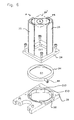
- the plate 24 is screwed with screws on a support plate 28 of a PA support selector ( Figure 6).
- This plate 28 comprises, to the right of the recess EV 1 of the plate 24, a recess having a platinum support side EV 2 adapted to the support plate PA, here circular, and, on the other side, a form, per rectangular example, EV 3 with rounded edges, whose section is slightly larger than the general surface of the support pieces PA.
- the longitudinal axis of this rectangular shape EV 3 extends obliquely with respect to the longitudinal axis of the support pieces PA when they are inside the magazine M, so that the support pieces PA can not naturally engage in the recess EV 3 without modification of orientation.
- This change of orientation is provided by a disk DR, rotatably mounted in the circular portion of the recess EV 2 , EV 3 , and whose rotation is controlled by a radial pin BR which engages in an oblong opening OB made in a lateral edge of the plate 28.
- This disk DR comprises a central recess EC of shape adapted to the support plate, for example of square shape, of dimensions substantially equal to the dimensions of the recess of the plate 24.
- the support piece PA contained in the recess EC of the disk DR is brought into the axis of the recess EV 3 and falls through it on slides G 1 , G 2 carrying a drawer T designed to bring the support pieces PA to a well PT located right of the ZV screwing zone ( Figures 3 and 4).
- the two slides G 1 , G 2 are carried by a plate PL fixed at its lateral edges on two pads PA 1 , PA 2 parallel, themselves respectively fixed on the underside of the parallel wings 3, 4 of the base 2.
- This plate PL comprises an oblong recess which extends axially between the two slides and which has, beyond the end of these two slides G 1 , G 2 , a shape corresponding to that of the support pieces PA, located to the right of the ZV screwing area.
- the plate PL is provided with a vertical rim RV which extends in the space between the pads to the level of their face lower part by forming the PT well in which the support pieces PA can engage and descend until they come to rest on the plane on which the apparatus is arranged (these support pieces PA are then in the position of screwing).
- the drawer T is constituted by a PM plate on which are fixed two lateral sections PL 1 , PL 2 which engage in longitudinal grooves RL 1 , RL 2 formed in the outer lateral edges of the slides G 1 , G 2 .
- This PM plate comprises on the side of the ZV screwing zone an oblong recess EV 4 of width slightly greater than the width of the support pieces PA.
- This recess EV 4 ends on one side with a rounded shape and is open on the other side at the transverse edge of the plate PM located at the screwing zone ZV.
- a support piece PS On the lower face of the plate PM is fixed a support piece PS on which are mounted two support rods TG 1 , TG 2 adapted to engage in holes made in the vertical flange RV.
- the spacing of these two rods TG 1 , TG 2 is slightly less than the width of the support pieces PA.
- the screws V 1 to V 3 used for this screwing are mounted in strips on a profiled piece of support S made of flexible plastic material.
- This profile has a U-shaped section comprising two wings A 1 , A 2 parallel connected by one of their edges by a core A 3 .
- These two wings comprise a plurality of pairs of notches EN 1 , EN 1 , -EN 2 , EN ' 2 -EN 3 , EN' 3 successive in which are clipped the rods of screws V 1 , V 2 , V 3 ( usually of significant length).
- edges of these notches may have shapes staggered so as to allow the assembly of screws of different sections.
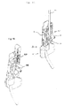
- this strip of screw engages and is guided in the guide device 18 to the screw distributor mechanism 20 illustrated in Figures 11 to 13c.
- This distributor uses a screw extractor 30 consisting of an extraction piece 31 of substantially U-shaped section, the two flanges 32, 33 comprise at their edges two respective coaxial notches 34, 35.
- This piece 31 is dimensioned so that the two wings 32, 33 can engage on either side of the support profile piece S so that the rod of the first screw V 3 of the strip can be introduced into the notches 34, 35.
- This piece 31 is pivotally mounted against the action of resilient means 36, on a slider 37 movable in vertical translation, guided by a slide integral with the screw guiding device and therefore the fixed structure of the device.
- This extractor further comprises an abutment piece consisting of an oscillating lever 38 having a spout 39, the tilting of this lever 38 being ensured by means of a cam profile provided in this lever 38, opposite the spout 39, in which circulates a pin 40 secured to the slider 37:
- the slider 37 causes a tilting of the lever 38 whose spout engages in the volume of passage of the screws so as to retain the screw following V 2 .
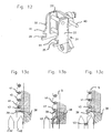
- FIGS. 13a to 13c The operation of this extractor is illustrated in FIGS. 13a to 13c on which only one of the two wings 32, 33 of the extraction piece 31 provided with its notch 34, 35, the spout 39 of the lever of stop 38 and the end of the screw strip.
- the end of the band is engaged in the distributor until the rod of the first screw V 3 of the band engages in the notches 34, 35 ( Figure 13a).
- the upper part of the wing of the extraction piece 31 has a bevel 41 ending at the notch 34, 35 while the lower part of this wing, located below the notch, is slightly prominent.
- the passage of the rod on the bevel 41 causes a slight tilting of the extraction member 31 relative to the slider 37 against the action of the elastic means 36.
- the engagement of the rod in the notches 34, 35 is then confirmed by returning the coin to its original position.
- the extractor 30 initiates a displacement in translation downwards by driving the screw V 3 and the support profile S.
- the rod of the screw V 3 slides on the bevelled end 42 of a screw guide device located downstream of the extraction device and is disengaged from the notch EN 3 , EN ' 3 .
- the screw V 3 thus released is guided by its head until it engages in a tubular centering and guide shaft 43 coaxial with the drilling of the support piece PA disposed in the screwing zone ZV.
- the extractor 30 returns to its initial position by causing the withdrawal of the spout 39, then the engagement of the screw shank V 2 in the notches 34, 35, by sliding on the bevel 41 The retention of the screw V 2 in the notches 34, 35 is ensured by the action of the elastic means 36.
- a new cycle can then be initiated.
- the screws are first held suspended by the head by means of a retaining device comprising two articulated levers 45, 46 on the shaft 43 and which comprise, in contrast to their hinge pin, a retaining nose 47, 48 intended to engage under the head of the screw V 3 .
- the two levers 45, 46 are held in this position by two respective counterweights 49, 50.
- the release of the screw V 3 is then obtained by the action of the screw bit 51 of the screwdriver 52, when the latter is brought into the screwing position.
- the barrel 43 comprises a slot longitudinal 53 closed by a tilting cover 54 so as to be able to access to the internal volume of the drum, in particular to extract a screw still used.
- the lower end of the barrel 43 engages in a centering device 55 of the screw which may for example comprise four radial pushers (or balls), opposed in pairs, and biased by springs so as to act on the screw V 3 to keep it centered even in the case where it has variations in diameter (especially at the head).
- a centering device 55 of the screw which may for example comprise four radial pushers (or balls), opposed in pairs, and biased by springs so as to act on the screw V 3 to keep it centered even in the case where it has variations in diameter (especially at the head).
- This centering means makes it possible to ensure that the tip of the screw V 3 reaches the hole PE located in the bottom of the bowl CC of the support piece PA with a maximum of precision, the curved shape of the bowl CC assuring the end of this centering.
- the screwdriver 52 used in this example is a portable electric screwdriver of conventional type on which is mounted a rod 56 carrying a screwdriver tip 51 suitable for the head of the screw V 3 .
- This screwdriver 52 is fixed at its nose on a vertically movable carriage CM formed of two horizontal support pieces PS 1 , PS 2 , of parallelepipedic shapes braced by two vertical connecting blades LV 1 , LV 2 as well as by two bearing tubes Vertical TP 1 , TP 2 which engage in corresponding through holes provided in support parts PS 1 , PS 2 .
- These bearing tubes TP 1 , TP 2 are slidably mounted on the two columns 8, 9.
- These two support pieces PS 1 , PS 2 further comprise two pairs of coaxial vertical bores in which engage and are fixed the upper ends of the two telescopic structures ST 1 , ST 2 .
- This tubular sleeve MC is intended to receive the nose of the screwdriver 52, the locking of this nose being obtained by wedging thanks to a cam system and with tilting lever LB.
- the screwdriver 52 is moved in vertical translation downwardly so that the screwdriver tip 51 engages the head of the screw in the centering shaft 43 and ensures the screwing of the screw.
- the invention uses the movements of the carriage CM along the columns 8, 9 to sequentially control the various elements of both distributors.
- the lower end of the training tube 55 comprises a protuberance external 61, provided with a bore, on which is engaged a clevis hinge 62, whose axis passes through said bore, mounted at the end of a link 63.
- the other end of the rod 63 is articulated, also by a clevis hinge 64, on a side flange 65 of the drawer T of the coin distributor PA support.
- This transverse wing 65 comprises an oblong recess 66 in which engages the pin BR of the disc of the selector DR of the support pieces PA.
- the arrangement of the rod 63 is such that, when the carriage CM is moved downwards from its rest position, position in which the drive tube 55 is held in the upper position by the stop 59 which bears on the PS 2 support part, the tube 55 descends under the effect of its own weight by driving the link 63 which pushes the drawer T in the retracted position.
- the stop 60 is driven downwards by the lower support piece PS 2 and causes movement of the drive tube 55 against the action of the spring 57.
- This movement of the drawer T causes a complete pivoting of the disk of the selector DR and, consequently, the descent of a support piece PA on the slides G 1 , G 2 .
- the CM carriage controls the moving the slider 37 of the screw distributor by means of a connecting rod TL secured to the CM carriage.
- This displacement of the slider 37 causes the extraction of a screw which, after have been guided by the slides 42 ', engages in the shaft 43 while being temporarily retained by the head through the spouts 47, 48 levers 49, 50.
- the tip 51 of the rod 56 of the screwdriver 52 is engaged at the entrance of the shaft 43.
- the passage of the tip 51 between the weights 45, 46 releases the screw V 3 .
- the screw slides in the barrel 43 until its tip engages in the bore PE of the support piece PA disposed in the screwing zone ZV.
- the bowl shape CC of this support piece PA then ensures self-centering from the tip.
- the tip 51 of the screwdriver 52 which also slides in the barrel 43, then engages on the head of the screw. The screwing of the screw can then be executed.
- the carriage CM At the end of screwing, the carriage CM is in the end-of-travel position defined by an adjustable end stop BF, in which position it compresses the springs ST 1 , ST 2 . The release of the CM carriage by the operator then causes its return to the high position.
- the displacement of the carriage CM causes the dispensers to perform the second part of their operating cycle (return of the drawer T in the retracted position of the disc of the selector DR in its initial position and of the extractor screw engaged with the next screw V 2 ).
- the carriage CM may include two side handles PL 1 , PL 2 adjustable in height and orientation.
- the base may include in its upper part one or several DC sockets of appropriate conformation to allow extraction by unscrewing the tip 51 so that the normal use of the device does not require the use of tools.
- the apparatus previously described applies particularly advantageous for fixing a waterproofing membrane on a coating of insulation placed on elements of blankets, carried by a frame.
- the screws may have a relatively large length and have a drill bit suitable for drilling steel tray covers and present a double net including a self-tapping net.
- This device is particularly ergonomic, the user remaining standing, and allows to obtain a very high productivity. It ensures a good quality of poses and a perfect hold of the supporting pieces in alignment with a orientation of the screw perpendicular to the support.
- the setting is fast and does not does not require a tool.
- the wear of the screwdriver bit is reduced thanks to the good alignment of the screws.
- the mechanisms used are of great reliability and easy maintenance.
- the standing position of the operator allows him to have a good overview of the site.
- the distribution mechanism of the support pieces can be designed from to allow the use of support pieces of shapes and dimensions different.
- Figures 16 and 17 show a distribution mechanism interchangeable that can be mounted (or removed) very easily on (or from) the base 2 without this operation affects the accuracy and reliability of the entire device.
- the plate PM ' which constitutes the drawer T' comprises, on the side of the screwing zone ZV, an oblong recess EV ' 4 of width slightly greater than the width of the support pieces PA.
- This recess EV ' 4 ends with a rounded shape and is open, on the other side, at the transverse edges of the plate PM' located on the side of the screwing zone.
- the plate PM ' carries two rods TG' 1 , TG ' 2 intended to temporarily retain the support pieces PA, when they are engaged below the screwing zone, the removal of the drawer T 'then causing the lowering of the support piece PA on this area.
- FIG. 6 shows a support plate PA ' square shape and a rectangular PA support plate inside of the support piece selector, it being understood that these bearing pieces PA, PA ' will find in similar positions in the various positions of the distribution mechanism.
- the slider 37 of the distributor of screw 20 may be driven by a PE training part possibly retractable, on which can come carry a stop driven by the trolley mobile MC.
- the rod TL provided in the previous example is deleted and a return spring RP is provided between the slider 37 and a support piece PS located in the extension of the slide on which moves the slide 37.
Landscapes
- Engineering & Computer Science (AREA)
- Mechanical Engineering (AREA)
- Connection Of Plates (AREA)
- Details Of Spanners, Wrenches, And Screw Drivers And Accessories (AREA)
- Earth Drilling (AREA)
- Toys (AREA)
Description
- des moyens de support et de guidage disposés de manière à recevoir les pièces d'appui délivrées par les moyens de distribution,
- un tiroir mobile en translation horizontale entre les moyens de support et de guidage et les moyens de distribution, ce tiroir étant destiné à déplacer chaque pièce d'appui délivrée par les moyens de distribution, le long des moyens de support et de guidage jusqu'à une zone située au-dessus d'un puits débouchant dans la zone de vissage,
- des éléments de support rétractables situés au-dessous des moyens de support et de guidage et solidaires du tiroir de manière à ce que lorsqu'elle se trouve au-dessus dudit puits, la pièce d'appui tombe sur les éléments de support rétractables, que la pointe de la vis s'engage dans le perçage de cette pièce d'appui et que le retour du tiroir en position initiale provoque la rétraction desdits éléments de support rétractables, cette rétraction provoquant le transfert de la pièce d'appui dans la zone de vissage sous l'effet de son poids et de celui de la vis engagée dans le perçage.
- Des moyens de guidage de la bande portant les vis à l'entrée du distributeur.
- Des moyens de préhension de la première vis de la bande, qui effectuent un déplacement pour venir en prise sur la vis et un mouvement de translation pour amener cette vis sur une rampe en provoquant son extraction de la bande et en faisant avancer la bande.
- Des moyens de guidage servant à amener la vis qui a été extraite de la bande dans une position coaxiale à l'emplacement de l'orifice de la pièce d'appui dans la zone de vissage.
- Des moyens de retenue rétractables étant prévus pour retenir la vis au-dessus de la zone de vissage tant qu'une pièce d'appui n'est pas présente dans cette zone de vissage.
- Une position dans laquelle l'évidement EC est axé obliquement par rapport à l'évidement EV1, position dans laquelle il vient en butée sur la face inférieure de la première pièce d'appui PA de la pile contenue dans le magasin M.
- Une position dans laquelle l'évidement EC est axé parallèlement à l'évidement EV1, position dans laquelle la première pièce d'appui PA de la pile s'engage dans l'évidement EC du disque tandis qu'il demeure retenu par les bords parallèles de la forme de l'évidement EV3.
- Initialement :
- le disque DR du sélecteur est axé obliquement par rapport au magasin et contient la première pièce d'appui de la pile,
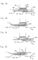
- le tiroir T est en position avancée, position dans laquelle l'évidement EV4 se trouve en regard de la zone de vissage ZV (position illustrée sur les figures 3 et 4 et sur la figure 9a).
- Au cours d'une première phase :
- le tiroir T est amené en position reculée jusqu'à ce que son évidement EV4 se trouve au droit de l'évidement EV3 de la plaque 28 du chargeur ; lorsque le tiroir T arrive dans cette position le disque DR a été entraíné en rotation par une action sur la broche BR de manière à ce que l'évidement se trouve orienté parallèlement à l'axe des pièces d'appui PA ; la première pièce d'appui PA de la pile tombe alors dans l'évidement EV4 et vient en appui sur les glissières G1, G2 (figure 9b).
- Au cours d'une deuxième phase :
- le tiroir T amorce son retour vers sa position avancée, cette action provoque la rotation du disque DR qui amène ainsi la pièce d'appui PA suivante dans l'évidement EC,
- le tiroir T poursuit son déplacement vers sa position avancée en entraínant la pièce d'appui PA qui coulisse sur les glissières G1, G2 grâce à une pièce d'entraínement solidaire de la plaque PM,
- en fin de course, la pièce d'appui PA se trouve au droit du puits PT de la plaque support PL des glissières et tombe dans ce puits PT en étant retenue par les tiges TG1, TG2 au-dessus de la zone de vissage ZV (figure 9c).
- Au cours d'une troisième phase (vissage) :
- le tiroir T est ramené en position reculée ; au cours de ce déplacement, les tiges TG1, TG2 s'extraient du puits PT dans lequel elles s'étaient précédemment engagées et libèrent la pièce d'appui PA qui tombe dans la zone de vissage ZV ; le vissage peut alors être effectué (figure 9d).
- une butée supérieure 59 destinée à coopérer avec la pièce de support inférieure PS2 du chariot CM pour ramener le tube d'entraínement 55 en position haute de repos, et
- une butée inférieure 60 destinée à coopérer avec la pièce de support inférieure PS2 du chariot CM en fin de course vers le bas pour déplacer le tube d'entraínement 55 vers le bas contre l'action du ressort 57.
- une platine 24 présentant un évidement de forme sensiblement carré supportant deux glissières 25, 26 en forme de cornière qui constitue un magasin apte à assurer le guidage et le stockage d'une pile de pièces d'appui PA ; les dimensions de l'évidement EV1 sont déterminées en fonction de celles des pièces d'appui PA à distribuer,
- un sélecteur de pièces d'appui PA comprenant une plaque 28 comportant un évidement qui présente, du côté platine 24, un appui EV2 adapté à la plaquette d'appui PA, de forme circulaire et, de l'autre côté, une forme carrée EV3 à bords arrondis, dont la section est légèrement plus grande que la surface projetée des pièces d'appui,
- un disque DR monté rotatif dans la partie circulaire de l'évidement EV2, EV3 et dont la rotation est assurée par une broche radiale BR qui s'engage dans une ouverture oblongue OB d'un bord latéral de la plaque 28 ; ce disque DR comprend un évidement central EC coaxial de forme carrée et de dimensions sensiblement égales aux dimensions des pièces d'appui (figure 6),
- un tiroir T' mobile au-dessous de la plaque 28 grâce à deux glissières G'1, G'2, pour amener les pièces d'appui PA jusqu'à un puits PT' situé au droit d'une zone de vissage,
- une plaque PL' qui porte les glissières G'1, G'2 et qui est elle-même supportée par les patins PA'1, PA'2, cette plaque PL' portant un évidement de forme correspondant à celle des pièces d'appui PA qui s'étend entre les deux glissières coaxialement à la zone de vissage ZV ; cette plaque est munie d'un rebord vertical RV' qui s'étend dans l'espace compris entre les patins PA'1, PA'2 jusqu'au niveau de leur face inférieure en constituant le puits PT' dans lequel les pièces d'appui PA peuvent s'engager et descendre jusqu'à ce qu'elles reposent sur le plan sur lequel est disposé l'appareil.
- La forme de l'extrémité intérieure de l'évidement EV'4 prévu sur la plaque PM est celle d'un triangle rectangle isocèle à angles arrondis dont la bissectrice est parallèle à l'axe de déplacement du tiroir. Ce triangle correspond sensiblement à la moitié de la forme carrée du sélecteur de pièces d'appui.
- La plaque PL' comprend au droit de la zone de vissage un orifice carrée OC dont les dimensions correspondent sensiblement à la forme carrée de l'évidement EC du sélecteur.
- L'aile latérale 65' du tiroir est dimensionnée de manière à ce que la position du perçage par lequel passe l'axe d'articulation de l'extrémité de la biellette 63 soit indépendant des dimensions du mécanisme de distribution (de manière à permettre l'interchangeabilité de mécanismes conçus pour des plaques d'appui PA différentes).
- Les patins PA'1, PA'2 sont équipés de moyens de fixation et de moyens de calage permettant une fixation précise et facilement démontable du mécanisme de distribution sur la face inférieure des ailes parallèles 3, 4 de l'embase.
Claims (14)
- Appareil pour le vissage d'éléments de fixation réalisés en au moins deux parties dont l'une est constituée par une pièce d'appui (PA) tandis que l'autre comprend une vis (V1 à V3) devant s'engager dans un perçage (PE) de la pièce d'appui (PA) lors du vissage, cet appareil comprenant des moyens de distribution de pièces d'appui (PA) aptes à amener une à une les pièces d'appui (PA) initialement empilées dans un magasin dans une zone de vissage (ZV), des moyens de distribution de vis permettant d'amener une à une les vis (V1 à V3) coaxialement à l'emplacement du perçage (PE) de la pièce d'appui (PA) lorsque celle-ci est positionnée dans la zone de vissage (ZV) et des moyens de vissage dont au moins un embout de vissage (51) est mobile en translation coaxialement à ladite vis et audit perçage (PE) de manière à venir en prise avec la tête de la vis et à effectuer le vissage,
caractérisé en ce que les susdits moyens de distribution de pièces d'appui (PA) comprennent :des moyens de support et de guidage disposés de manière à recevoir les pièces d'appui (PA) délivrées par les moyens de distribution,un tiroir (T) mobile en translation horizontale entre les moyens de support et de guidage (G1, G2) et les moyens de distribution, ce tiroir étant destiné à déplacer chaque pièce d'appui délivrée par les moyens de distribution, le long des moyens de support et de guidage jusqu'à une zone située au-dessus d'un puits débouchant dans la zone de vissage (ZV),des éléments de support rétractables (TG1, TG2) situés au-dessous des moyens de support et de guidage (G1, G2) et solidaires du tiroir de manière à ce que lorsqu'elle se trouve au-dessus dudit puits, la pièce d'appui tombe sur les éléments de support rétractables, que la pointe de la vis s'engage dans le perçage de cette pièce d'appui et que le retour du tiroir en position initiale provoque la rétraction desdits éléments de support rétractables, cette rétraction provoquant le transfert de la pièce d'appui (PA) dans la zone de vissage (ZV) sous l'effet de son poids et de celui de la vis engagée dans le perçage. - Appareil selon la revendication 1,
caractérisé en ce que les pièces d'appui (PA) présentent une forme oblongue comportant deux bords longitudinaux parallèles, et en ce que le tiroir (T) consiste en une platine munie d'un évidement allongé (EV4) de largeur sensiblement supérieure à celle des pièces d'appui (PA), cet évidement étant axé parallèlement à l'axe de déplacement de la platine. - Appareil selon la revendication 2,
caractérisé en ce que les pièces d'appui (PA), stockées dans le magasin (M ; 24 à 26), sont axées obliquement par rapport audit axe et des moyens sont alors prévus pour faire pivoter la première pièce d'appui (PA) de la pile de manière à lui permettre de s'engager (elle seule) dans l'évidement du chariot (EV4), et à pouvoir être entraínée par ce dernier jusqu'aux éléments de support rétractables (TG1, TG2). - Appareil selon la revendication 3,
caractérisé en ce que le susdit magasin, les moyens de distribution et l'évidement du chariot sont conçus de manière à assurer la distribution de pièces d'appui de forme oblongue et/ou de forme carrée. - Appareil selon l'une des revendications précédentes,
caractérisé en ce que les vis (V1 à V3) sont préalablement montées de façon détachable sur des profilés de supports souples (S) de manière à être disposées parallèlement les unes aux autres et espacées les unes des autres d'une distance prédéterminée (pas) en formant une bande. - Appareil selon la revendication 5,
caractérisé en ce que le distributeur de vis comprend :des moyens de guidage du profilé de support (S) portant les vis à l'entrée du distributeur,des moyens de préhension de la première vis (V3) de la bande, qui effectuent un déplacement pour venir en prise sur la vis et un mouvement de translation pour amener cette vis sur une rampe (42) en provoquant son extraction de la bande et en faisant avancer le profilé (S),des moyens de guidage (42') servant à amener la vis (V3) qui a été extraite de la bande dans une position coaxiale à l'emplacement du perçage (PE) de la pièce d'appui (PA) dans la zone de vissage (ZV),des moyens de retenue rétractables (45, 46) étant prévus pour retenir la vis (V3) au-dessus de la zone de vissage (ZV) tant qu'une pièce d'appui (PA) n'est pas présente dans cette zone de vissage (ZV). - Appareil selon la revendication 6,
caractérisé en ce que les susdits moyens de préhension comprennent une pièce d'extraction (31) de section en forme de U dont les ailes (32, 33) comprennent au niveau de leurs bordures deux encoches respectives coaxiales (34, 35), cette pièce (31) étant dimensionnée de manière à ce que les deux ailes (32, 33) puissent s'engager de part et d'autre des profilés de support (S) de manière à ce que la tige de la première vis (V3) de la bande puisse s'introduire dans les encoches. - Appareil selon la revendication 7,
caractérisé en ce que la susdite pièce d'extraction (31) est montée pivotante contre l'action de moyens élastiques (36) sur un coulisseau (37) mobile en translation verticale, guidé par une glissière solidaire de la structure fixe de l'appareil. - Appareil selon l'une des revendications 6 à 8,
caractérisé en ce que le distributeur de vis comprend en outre une pièce de butée consistant en un levier oscillant (38) présentant un bec (39), dont le basculement est assuré grâce à un profil de came prévu dans le levier (38), sur lequel vient circuler une pièce (40) solidaire de la pièce d'extraction (31). - Appareil selon l'une des revendications précédentes,
caractérisé en ce qu'il comprend une structure rigide (châssis) constituée par une embase montée sur des roues et par une glissière verticale sur laquelle coulisse un chariot portant un guidon muni de poignées servant à la fois à assurer les déplacements par roulage de l'appareil et à permettre d'imprimer un déplacement en translation à une visseuse axée verticalement et portant le susdit embout de vissage. - Appareil selon la revendication 10,
caractérisé en ce que le susdit embout de vissage est monté sur une tige pour former un ensemble qui s'engage et coulisse dans un fût de centrage et de guidage tubulaire coaxial au perçage de la pièce d'appui disposée dans la zone de vissage (ZV), et dans lequel débouche un dispositif de guidage des vis situé en aval du susdit dispositif d'extraction. - Appareil selon la revendication 11,
caractérisé en ce que le susdit fût comprend, dans sa partie supérieure, des moyens de retenue temporaire de la tête des vis. - Appareil selon l'une des revendications 1 et 12,
caractérisé en ce que le susdit fût comprend un dispositif de centrage des vis comprenant des poussoirs radiaux sollicités par des ressorts. - Appareil selon l'une des revendications 10 à 13,
caractérisé en ce que les susdits moyens de distribution de pièces d'appui présentent une structure modulaire interchangeable et comprend des moyens permettant leur montage et démontage rapides sur le susdit châssis, de manière à permettre l'usage de pièces d'appui de formes et de dimensions différentes.
Applications Claiming Priority (2)
| Application Number | Priority Date | Filing Date | Title |
|---|---|---|---|
| FR0212211 | 2002-10-02 | ||
| FR0212211A FR2845302B1 (fr) | 2002-10-02 | 2002-10-02 | Appareil pour le vissage d'elements de fixation |
Publications (2)
| Publication Number | Publication Date |
|---|---|
| EP1405697A1 EP1405697A1 (fr) | 2004-04-07 |
| EP1405697B1 true EP1405697B1 (fr) | 2005-04-20 |
Family
ID=31985408
Family Applications (1)
| Application Number | Title | Priority Date | Filing Date |
|---|---|---|---|
| EP20030292417 Expired - Lifetime EP1405697B1 (fr) | 2002-10-02 | 2003-10-01 | Appareil pour le vissage d'elements de fixation |
Country Status (3)
| Country | Link |
|---|---|
| EP (1) | EP1405697B1 (fr) |
| DE (1) | DE60300533T2 (fr) |
| FR (1) | FR2845302B1 (fr) |
Families Citing this family (10)
| Publication number | Priority date | Publication date | Assignee | Title |
|---|---|---|---|---|
| FR2872796B1 (fr) * | 2004-07-06 | 2006-09-22 | L R Etanco Soc Par Actions Sim | Dispositif de conditionnement d'elements de fixation |
| DE102006045394B4 (de) * | 2006-09-26 | 2014-01-09 | Ateliers Lr Etanco | Einschraubvorrichtung und Vereinzelungsverfahren für Befestigungselemente |
| DE102010048775A1 (de) * | 2010-10-18 | 2012-04-19 | Sfs Intec Holding Ag | Vorrichtung zum Eindrehen von Schrauben |
| DE102012101380A1 (de) * | 2012-02-21 | 2013-08-22 | Sfs Intec Holding Ag | Gerät zum Verkleben oder Verschweißen einer Dachbahn |
| USD719596S1 (en) | 2012-12-20 | 2014-12-16 | Sfs Intec Holding Ag | Induction apparatus |
| DE102014004717A1 (de) * | 2014-04-01 | 2015-10-01 | Kolbus Gmbh & Co. Kg | Vorrichtung zum Einbringen von Magneten |
| DE202014004803U1 (de) | 2014-06-05 | 2014-07-21 | Etanco Gmbh | Einschraubvorrichtung für die Linienbefestigung von Dachdichtungsbahnen und/oder Isoliermaterial auf Flachdächern |
| JP5677614B1 (ja) | 2014-07-30 | 2015-02-25 | 株式会社ムロコーポレーション | ワッシャー積層供給機構付き連続ビス締め付け機 |
| US12291875B1 (en) | 2019-12-11 | 2025-05-06 | Scepaniak IP Holdings, LLC | Commercial roofing screw machine |
| CN115008149B (zh) * | 2022-06-09 | 2025-01-28 | 安徽省隆裕休闲家具有限公司 | 一种户外编藤椅配件自动组装设备 |
Family Cites Families (5)
| Publication number | Priority date | Publication date | Assignee | Title |
|---|---|---|---|---|
| DE8707666U1 (de) * | 1987-05-28 | 1987-11-19 | Zahn, Harald, 6906 Leimen | Vorrichtung zum maschinellen Befestigen von Dachdichtungsfolien und zugehöriger Dämmstoffe auf Trapezblechen, Gasbeton- oder Flachdächern |
| US5056684A (en) * | 1989-02-15 | 1991-10-15 | Illinois Tool Works Inc. | Roofing washer-dispensing machine |
| DE4413039C1 (de) * | 1994-04-15 | 1995-06-22 | Ivt H Blank | Setzvorrichtung zum Setzen von Haltetellern |
| DE29614243U1 (de) * | 1996-08-16 | 1996-10-10 | Harald Zahn GmbH, 69168 Wiesloch | Vorrichtung zum Befestigen von Dachdichtungs- und Isoliermaterial auf Flachdächern |
| US5921454A (en) * | 1998-05-05 | 1999-07-13 | Illinois Tool Works Inc. | Roofing washer-dispensing and fastener-driving machine |
-
2002
- 2002-10-02 FR FR0212211A patent/FR2845302B1/fr not_active Expired - Lifetime
-
2003
- 2003-10-01 EP EP20030292417 patent/EP1405697B1/fr not_active Expired - Lifetime
- 2003-10-01 DE DE2003600533 patent/DE60300533T2/de not_active Expired - Lifetime
Also Published As
| Publication number | Publication date |
|---|---|
| FR2845302A1 (fr) | 2004-04-09 |
| DE60300533T2 (de) | 2006-02-23 |
| DE60300533D1 (de) | 2005-05-25 |
| FR2845302B1 (fr) | 2005-07-08 |
| EP1405697A1 (fr) | 2004-04-07 |
Similar Documents
| Publication | Publication Date | Title |
|---|---|---|
| CA1200425A (fr) | Embrocheur pour la preparation de brochettes de viande et/ou autres produits alimentaires | |
| EP2003268B1 (fr) | Attache de support et de fixation d'une structure sur une paroi, structure associée, et ensemble de structure correspondant | |
| EP1405697A1 (fr) | Appareil pour le visage d'elements de fixation | |
| FR2488169A1 (fr) | Ensemble d'un coulisseau et d'un porte-outil pour tour vertical ou machine analogue | |
| EP1605242B1 (fr) | Système pour l'utilisation d'un dispositif de prélèvement d'échantillons dans un sol ou un matériau de constitution granuleuse ou pulvérulente | |
| FR2628021A1 (fr) | Appareil de scellement actionne par l'energie de la poudre | |
| EP2431555B1 (fr) | Verrou de trappe extérieur | |
| CH373688A (fr) | Procédé pour insérer une ébauche de séparation pliable entre des rangées de récipients à emballer et machine pour la mise en oeuvre de ce procédé | |
| WO2011069956A1 (fr) | Table à rallonge | |
| FR2507945A1 (fr) | Accessoires de mecanisme de serrage plus particulierement pour etau ou etabli | |
| FR2796872A1 (fr) | Appareil pour le vissage d'elements de fixation | |
| FR2898069A1 (fr) | Appareil pour le vissage, semi-automatique, d'elements de fixation | |
| EP1796876B1 (fr) | Appareil pour le vissage, semi-automatique, d'elements de fixation. | |
| EP1089850B1 (fr) | Dispositif de ravitaillement d'une machine-outil en barres a usiner | |
| EP0067760A1 (fr) | Dispositif de distribution, d'orientation et de positionnement d'axes sur machine automatique | |
| FR3010988A1 (fr) | Conteneur de collecte des dechets dote d’un systeme perfectionne de commande d'ouverture/fermeture automatique de trappe de vidage | |
| EP3246280B1 (fr) | Dispositif de retenue pour un enrouleur | |
| FR2875723A1 (fr) | Appareil pour le vissage, semi-automatique, d'elements de fixation | |
| FR2478513A1 (fr) | Dispositif d'alimentation automatique de barres dans une machine-outil | |
| FR2875724A1 (fr) | Appareil pour le vissage, semi-automatique, d'elements de fixation | |
| FR2602158A1 (fr) | Cisaille-guillotine a commande numerique equipee d'un dispositif d'alimentation | |
| WO1992008359A1 (fr) | Machine pour la preparation de brochettes | |
| EP3256225B1 (fr) | Dispositif de maintien pour bicyclette et ensemble dedie a l'entrainement sur bicyclette en position stationnaire | |
| FR2527826A1 (fr) | Dispositif de commande des barres absorbantes dans un systeme de pilotage d'un reacteur nucleaire | |
| FR3033345A1 (fr) | Bac, ensemble comprenant un tel bac et procede d'installation d'un tel ensemble sur une paroi |
Legal Events
| Date | Code | Title | Description |
|---|---|---|---|
| PUAI | Public reference made under article 153(3) epc to a published international application that has entered the european phase |
Free format text: ORIGINAL CODE: 0009012 |
|
| 17P | Request for examination filed |
Effective date: 20031010 |
|
| AK | Designated contracting states |
Kind code of ref document: A1 Designated state(s): AT BE BG CH CY CZ DE DK EE ES FI FR GB GR HU IE IT LI LU MC NL PT RO SE SI SK TR |
|
| AX | Request for extension of the european patent |
Extension state: AL LT LV MK |
|
| GRAP | Despatch of communication of intention to grant a patent |
Free format text: ORIGINAL CODE: EPIDOSNIGR1 |
|
| AKX | Designation fees paid |
Designated state(s): DE FR |
|
| GRAS | Grant fee paid |
Free format text: ORIGINAL CODE: EPIDOSNIGR3 |
|
| GRAA | (expected) grant |
Free format text: ORIGINAL CODE: 0009210 |
|
| AK | Designated contracting states |
Kind code of ref document: B1 Designated state(s): DE FR |
|
| REG | Reference to a national code |
Ref country code: IE Ref legal event code: FG4D Free format text: LANGUAGE OF EP DOCUMENT: FRENCH |
|
| REF | Corresponds to: |
Ref document number: 60300533 Country of ref document: DE Date of ref document: 20050525 Kind code of ref document: P |
|
| PLBE | No opposition filed within time limit |
Free format text: ORIGINAL CODE: 0009261 |
|
| STAA | Information on the status of an ep patent application or granted ep patent |
Free format text: STATUS: NO OPPOSITION FILED WITHIN TIME LIMIT |
|
| 26N | No opposition filed |
Effective date: 20060123 |
|
| REG | Reference to a national code |
Ref country code: FR Ref legal event code: CA Ref country code: FR Ref legal event code: RM |
|
| REG | Reference to a national code |
Ref country code: FR Ref legal event code: PLFP Year of fee payment: 14 |
|
| REG | Reference to a national code |
Ref country code: FR Ref legal event code: PLFP Year of fee payment: 15 |
|
| REG | Reference to a national code |
Ref country code: FR Ref legal event code: PLFP Year of fee payment: 16 |
|
| PGFP | Annual fee paid to national office [announced via postgrant information from national office to epo] |
Ref country code: FR Payment date: 20220906 Year of fee payment: 20 |
|
| PGFP | Annual fee paid to national office [announced via postgrant information from national office to epo] |
Ref country code: DE Payment date: 20221012 Year of fee payment: 20 |
|
| P01 | Opt-out of the competence of the unified patent court (upc) registered |
Effective date: 20230526 |
|
| REG | Reference to a national code |
Ref country code: DE Ref legal event code: R071 Ref document number: 60300533 Country of ref document: DE |