EP1405428B1 - Funkempfänger und kanalabschätzer - Google Patents
Funkempfänger und kanalabschätzer Download PDFInfo
- Publication number
- EP1405428B1 EP1405428B1 EP01934731A EP01934731A EP1405428B1 EP 1405428 B1 EP1405428 B1 EP 1405428B1 EP 01934731 A EP01934731 A EP 01934731A EP 01934731 A EP01934731 A EP 01934731A EP 1405428 B1 EP1405428 B1 EP 1405428B1
- Authority
- EP
- European Patent Office
- Prior art keywords
- window
- radio
- searcher
- code
- delay
- Prior art date
- Legal status (The legal status is an assumption and is not a legal conclusion. Google has not performed a legal analysis and makes no representation as to the accuracy of the status listed.)
- Expired - Lifetime
Links
- 238000001228 spectrum Methods 0.000 claims description 20
- 239000000872 buffer Substances 0.000 claims description 19
- 230000004044 response Effects 0.000 claims description 16
- 230000007480 spreading Effects 0.000 claims description 14
- 230000003111 delayed effect Effects 0.000 claims description 8
- 238000001514 detection method Methods 0.000 claims description 8
- 230000003139 buffering effect Effects 0.000 claims description 6
- 230000001934 delay Effects 0.000 description 20
- 108010076504 Protein Sorting Signals Proteins 0.000 description 13
- 238000010586 diagram Methods 0.000 description 10
- 230000000875 corresponding effect Effects 0.000 description 9
- 238000005516 engineering process Methods 0.000 description 6
- 238000009825 accumulation Methods 0.000 description 5
- 230000001427 coherent effect Effects 0.000 description 5
- 238000004891 communication Methods 0.000 description 5
- 230000008901 benefit Effects 0.000 description 3
- 230000005540 biological transmission Effects 0.000 description 3
- 230000002596 correlated effect Effects 0.000 description 2
- 230000003247 decreasing effect Effects 0.000 description 2
- 230000010363 phase shift Effects 0.000 description 2
- 230000009466 transformation Effects 0.000 description 2
- MLJYKRYCCUGBBV-YTWAJWBKSA-N 4-nitrophenyl beta-D-xyloside Chemical compound O[C@@H]1[C@@H](O)[C@H](O)CO[C@H]1OC1=CC=C([N+]([O-])=O)C=C1 MLJYKRYCCUGBBV-YTWAJWBKSA-N 0.000 description 1
- 101100403808 Drosophila melanogaster Nach gene Proteins 0.000 description 1
- 101100452786 Schizosaccharomyces pombe (strain 972 / ATCC 24843) ire1 gene Proteins 0.000 description 1
- 101100298369 Schizosaccharomyces pombe (strain 972 / ATCC 24843) ppk5 gene Proteins 0.000 description 1
- 230000008859 change Effects 0.000 description 1
- 230000001276 controlling effect Effects 0.000 description 1
- 230000002452 interceptive effect Effects 0.000 description 1
- 238000000034 method Methods 0.000 description 1
- 230000002035 prolonged effect Effects 0.000 description 1
- 230000003595 spectral effect Effects 0.000 description 1
Images




Classifications
-
- H—ELECTRICITY
- H04—ELECTRIC COMMUNICATION TECHNIQUE
- H04B—TRANSMISSION
- H04B1/00—Details of transmission systems, not covered by a single one of groups H04B3/00 - H04B13/00; Details of transmission systems not characterised by the medium used for transmission
- H04B1/69—Spread spectrum techniques
- H04B1/707—Spread spectrum techniques using direct sequence modulation
- H04B1/7073—Synchronisation aspects
- H04B1/7075—Synchronisation aspects with code phase acquisition
- H04B1/70754—Setting of search window, i.e. range of code offsets to be searched
-
- H—ELECTRICITY
- H04—ELECTRIC COMMUNICATION TECHNIQUE
- H04B—TRANSMISSION
- H04B1/00—Details of transmission systems, not covered by a single one of groups H04B3/00 - H04B13/00; Details of transmission systems not characterised by the medium used for transmission
- H04B1/69—Spread spectrum techniques
- H04B1/707—Spread spectrum techniques using direct sequence modulation
- H04B1/7097—Interference-related aspects
- H04B1/711—Interference-related aspects the interference being multi-path interference
- H04B1/7113—Determination of path profile
-
- H—ELECTRICITY
- H04—ELECTRIC COMMUNICATION TECHNIQUE
- H04B—TRANSMISSION
- H04B1/00—Details of transmission systems, not covered by a single one of groups H04B3/00 - H04B13/00; Details of transmission systems not characterised by the medium used for transmission
- H04B1/69—Spread spectrum techniques
- H04B1/707—Spread spectrum techniques using direct sequence modulation
- H04B1/7097—Interference-related aspects
- H04B1/711—Interference-related aspects the interference being multi-path interference
- H04B1/7115—Constructive combining of multi-path signals, i.e. RAKE receivers
- H04B1/7117—Selection, re-selection, allocation or re-allocation of paths to fingers, e.g. timing offset control of allocated fingers
-
- H—ELECTRICITY
- H04—ELECTRIC COMMUNICATION TECHNIQUE
- H04B—TRANSMISSION
- H04B2201/00—Indexing scheme relating to details of transmission systems not covered by a single group of H04B3/00 - H04B13/00
- H04B2201/69—Orthogonal indexing scheme relating to spread spectrum techniques in general
- H04B2201/707—Orthogonal indexing scheme relating to spread spectrum techniques in general relating to direct sequence modulation
- H04B2201/70707—Efficiency-related aspects
- H04B2201/7071—Efficiency-related aspects with dynamic control of receiver resources
Definitions
- the present invention relates to a radio channel estimator and a radio receiver for a spread spectrum signal sequence.
- figure 1 a mobile station MS acting as a transmitter and a radio base station BTS acting as a receiver of a radio transmitted data stream.
- the signal sequence is transmitted over various propagation paths P1-P5, one of the paths P1 in this example is a direct wave from the transmitter to the receiver while on the remaining propagation paths the signal wave is reflected by various obstacles OB.
- P1-P5 one of the paths P1 in this example is a direct wave from the transmitter to the receiver while on the remaining propagation paths the signal wave is reflected by various obstacles OB.
- FIG 1 for the sake of simplicity just one or two reflections for each wave are shown, however, in practise multi reflections are common.
- the signal sequence sent from the transmitter will be received by the receiver as a number of versions of the original data stream mutually delayed and thus interfering with each other.
- a big leap in radio transmission technology was the introduction of digital signal processing in the transmitters and receivers that enabled the resolution of various versions of a data stream received over the various propagation paths P1-P5.
- the signal energy from selected ones of the various signal paths can be collected in the receiver.
- the signal energy received origins from the signal energy transmitted and thereafter split on the various ways and decreased due to propagation losses.
- a prerequisite for the resolution of a data stream received over the various propagation paths P1-P5 is that the various propagation path delays are known.
- the channel impulse response CHIR is shown in a diagram of power vs. time.
- the various power peaks PPK1-PPK5 in the diagram corresponds to the different propagation paths P1-P5.
- the propagation delays ⁇ 1 , ⁇ 2 , ⁇ 3 are indicated and the mutual differences ⁇ 2 , ⁇ 3 in propagation delay between the propagation paths are found in the channel impulse response CHIR.
- a radio receiver comprises a radio channel estimator that estimates the propagation delays of the various propagation paths.
- a radio spectrum band is shared by multiple users on code division basis.
- each user is given a unique spreading code that identifies a radio communication channel dedicated to the specific user.
- the spreading code also functions as to broaden the frequency band of the original user data. This implies that the spreading code rate is considerable higher than the user data rate, since frequency bandwidth is proportional to the data rate.
- Figure 3a shows the principle of bandspreading the power spectral density of the user data, where the user data power originally is gathered in a narrow user data spectrum band NSB but with the spreading code added to it the power is spread over a wider band SSB.
- Figure 3b shows the principle of multiple access in DS-CDMA technology, where the bandspread signal power of multiple users is transmitted in the same radio frequency band SSB.
- Radio communication channels RCH of the various users can be resolved in receivers by the unique spreading codes.
- Figure 4 shows some essential parts in a DS-CDMA transmitter.
- the transmitter is fed by a user data stream UDS on one input and by a pilot data stream PS on another input.
- a corresponding unique spreading code sequence PN P , PN D is added to the pilot data stream PS and to the user data stream UDS.
- PN P , PN D is added to the pilot data stream PS and to the user data stream UDS.
- PN P , PN D is added to the pilot data stream PS and to the user data stream UDS.
- PN P unique spreading code sequence
- PN D is added to the pilot data stream PS and to the user data stream UDS.
- PN P unique spreading code sequence
- PN D is added to the pilot data stream PS and to the user data stream UDS.
- the spread pilot data stream PS is phase shifted 90 degrees and thereafter the bandspreaded pilot data stream and data stream are combined.
- the data streams are modulated on an analogue radio wave and amplified before transmission. However, modulator, amplifier and antenna
- Figure 5 shows a radio channel estimator S1, hereafter called searcher S1, for estimating the channel impulse response CHIR of figure 2 .
- the channel impulse response CHIR is also called the delay profile CHIR.
- the searcher S1 is also arranged to keep track of changing propagation conditions. However, for reasons that will be described further down in the description, only the propagation delays that fits into a first window WW1 indicated in figure 2 will be detected in the searcher. In this example the first three propagation paths P1-P3 are within the first window WW1.
- the searcher receives on its input the energy of the whole spectrum band concerned SSB.
- the searcher is arranged to find correlations between the various propagation paths delays of pilot spreading code stream PN P sent from the transmitter and its complex conjugate code stream PN P * generated in the receiver.
- Figure 9 shows a received signal sequence (r) as well a period of the conjugate pilot code stream PN P * that the searcher S1 operates on.
- the sequence of the received signal(r) is combined with the complex conjugate code stream PN P *.
- the combination is repeated a large number of times and for each combination the spreading code phase is increased.
- the total numbers of combinations thus corresponds to a certain phase length variation of the conjugate pilot code stream PN P *.
- a correlation occurs for some of the combinations, and each correlation corresponds to a propagation path having a propagation delay equal to the delay of the added complex conjugate code PN P *.
- the searcher in figure 5 comprises a buffer B51 for buffering the sequence of the received signal(r) to operate on and a code generator CG arranged to produce the complex conjugate code stream PN P *. It further comprises a delaying means DM5 with an input from the code generator CG and a multiplier M51 with an input from the delaying means DM5 and an input from the buffer B51 for the received sequence of the signal(r).
- the complex conjugate code stream PN P * is combined with the received signal sequence (r) in the multiplier M51 and the combined sequence is fed to a correlation detector CD.
- the code generator CG, the delaying means DM5 and the correlation detector CD are controlled by a processor CPU.
- the processor CPU controls the delay produced in the delaying means DM5 and the buffer B51 and receives from the correlation detector CD information on when correlation occurs.
- the processor CPU registers the delays that produce correlation.
- the searcher S1 monitors the spectrum to track changes in the propagation conditions. To track the power peaks PPK1-PPK3 when the propagation delays varies the first window WW1 is moved in time.
- FIG 6 shows a Rake receiver R1 arranged for separately demodulating the various propagation paths P1-P3 of the spectrum spread user data stream UDS that fit into a first window WW1 indicated in figure 2 .
- the Rake receiver R1 comprises a set of fingers f1-f3, each of the fingers f1-f3 for handling one of the propagation paths P1-P3.
- the Rake receiver R1 also comprises a code generator CG for generating the complex conjugate code stream PN D * of the spreading code sequence PN D used in the transmitter for bandspreading the user data stream UDS.
- a delaying means DM6 at the output of the code generator CG is arranged to delay the conjugate code stream PN D * a length corresponding to the longest of the propagation delays ⁇ 3 .
- the bandspread user data stream of the various propagation paths is time aligned.
- the delayed conjugate code stream PN D * is combined in each finger f1-f3 with the time aligned data streams.
- the delay applied is selected to correlate the conjugate code stream PN D * with time aligned pilot spreading code PN P , and thereby the user data stream is de-spread and its energy is re-gathered in the narrow spectrum band NSB.
- an integrator ITR collects energy over short periods and feeds the collected energy to a demodulator DMD. At its output the demodulator produces a complex value.
- the real part of complex value of all fingers f1-f3 are added and based on this addition a decoding decision is made on every bit in the user data stream UDS.
- Such combining before a decision is often referred to as soft combining.
- EP 952 750 discloses a searcher that uses two window sets to estimate the propagation profile of the same radio link.
- D1 is directed to the problem of tracking the power peaks of the delay profile as, their delay in the window change.
- the solution to this problem as disclosed in D1 is to let one of the windows be long enough to embrace all peaks of the delay profile, while the second window shall be as small as possible.
- the large window is kept relatively fixed in position, while the short window position is adjusted to follow the delay variations of the peaks.
- WO 96/04716 discloses a searcher having a short and a long window operating on the same radio link. Just as in D1, the small window overlaps with the large window. The purpose of providing two windows is to minimize the total time for acquisition by speeding up the search methodology without incurring excessive penalties for false acquisition.
- WO 99/57819 relates to a searcher with a search window, and to the problem of tracking.
- the solution involves computing a channel impulse response (CHIR) mean position or delay and to adjust the window position to minimize any error between the position of the window centre and the CHIR mean position.
- CHIR channel impulse response
- the international patent application, WO 99/63677 A1 discloses a searcher unit estimating delay profiles CHIR for different sectors of the cell.
- the power spectrum is received by a sectorised antenna system and the power received in separate sectors is handled by separate window sets in the searcher.
- the window WW1 was prolonged the last two power peaks of the delay profile CHIR would also be detected. However, this would cost a large computation capacity in the searcher S1 because the length L1 of the window WW1 corresponds to the variation in phase length PHL and thus to the number of combinations of the signal sequence (r) with the delayed conjugate pilot code stream PN P * .
- the first window WW1 length is selected as a trade-off between the demand for low complexity and low processor capacity on one hand and the demand for handling propagation paths with a great variety in propagation delays on the other hand.
- the first window WW1 length is selected to be able to cope with the differences in propagation paths delays that occur in average radio environments and somewhat worse environments.
- the radio base stations BTS are positioned at various sites comprising various radio environments the propagation delays vary greatly. Especially in mountain areas and close to lakes, a line of sight propagation wave P1 and a propagation path P4 reflected over a lake or by a mountain far away have a great difference in propagation delay.
- radio base stations BTS would have to be implemented with processor capacity and with a complexity that for most sites will not be needed.
- a problem related to a prior art a searcher or a Rake receiver is how to fulfil the conflicting requirements on low complexity and processor capacity on one hand and ability to detect multipath propagation waves with a wide range in propagation delays on the other hand.
- a radio channel estimator that includes two or more window sets for estimating a radio channel impulse response in a respective window.
- the window sets are arranged to be alternatively allocated to estimate the channel impulse response on separate radio links or on the same radio link and when allocated to the same radio link the windows are arranged to be adjacent in time
- the invention also relates to a rake receiver comprising the inventive searcher.
- An advantage provided by the inventive searcher is that its delay profile resources are flexibly allocated for estimating a long delay profile of just one or a few radio links or, alternatively, the resources are allocated for detecting a short delay profile of two or more radio links. For example, when the searcher is used in a radio environment that produces a great variety in the delay spread of different propagation paths, the searcher is switched into the multiple window mode and two or more windows of the searcher are allocated for detecting the delay profile of one radio link. However, when the searcher is used in a radio environment causing less variety in delay spreads the searcher is switched into the single window mode and the separate window resources of the searcher are allocated to separate radio links, such that the searcher thereby is able to handle more radio links.
- An advantage provided by the inventive Rake receiver is that less capacity is needed in the beginning of the fingers for buffering of the input signal sequence because time alignment of various propagation paths need only to be made with respect to the fingers of the same set.
- the value streams at the output of the fingers are time aligned before being fed to the bit decoder. However, these value streams are less complex than the input signal sequence at the fingers and thus need less buffering capacity for the time alignment.
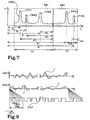
- FIG 7 the same diagram over the channel impulse response CHIR as in figure 2 is shown, i.e. the channel impulse response CHIR for the radio link from the mobile MS to the radio base station BTS in figure 1 .
- a second window WW2 adjacent of the first window WW1 is indicated.
- the second window WW2 embraces the last two power peaks PPK4-PPK5 of the channel impulse response CHIR.
- a radio base station BTS is arranged for handling communication over several radio links, i.e. with several mobile stations MS.
- Figure 1 shows by means of example only one mobile station with a radio link, whereby the radio link is represented by its propagation paths P1-P5. If there where more mobile stations MS, radio links established to them would have an own characteristic channel impulse response CHIR. In the following description the term delay profile CHIR will be used in stead of channel impulse response CHIR.
- the radio base station BTS is arranged with a single window mode searcher S8a to enable estimation of several radio channel RCH delay profiles CHIR.
- Figure 8a shows the single window mode searcher S8a.
- the searcher S8a is based on the basic searcher S1 shown in figure 5 but has several window sets WWS1, WWS2 each for handling one radio link.
- the single window mode searcher S8a is arranged for estimating the delay profile CHIR of a radio link in one corresponding window WW1.
- the window set WWS1, WWS2 includes a buffer B8 for buffering a sequence of the received signal sequence r, a delaying means DM1, DM2 for variously delay a received complex conjugate of the specific spreading code PN P * of the pilot data stream of interest.
- the window set WWS1, WWS2 further includes a multiplier M81, M82 that receives the delayed conjugate code PN P * from the delaying means DM1, DM2 and receives from the buffer B8 a sequence of the radio signal r and feeds a correlation detector CD1, CD2, at its output, with the sequence of received spectra multiplied with conjugate pilot code PN P *.
- the searcher S8a also includes a code generator CG for each of the window sets WWS1, WWS2, and a central processor CPU for control of all window sets WWS1, WWS2 and for control of the code generators CG.
- a unique pilot spreading code PN P is allocated to each of the mobile stations MS and serves to identify the respective radio links.
- the complex conjugate code PN P *, PN PX * generated in the code generators of the searcher S8a defines for which of the mobile stations a delay profile will be estimated in the corresponding window set WWS1, WWS2.
- Figure 9 shows a sequence of the radio signal stream r as a function of time, i.e. the radio signal received at the input of the radio base station BTS.
- the physical radio signal is described by a curve of its imaginary Im ⁇ r ⁇ and real part Re ⁇ r ⁇ respectively.
- Figure 9 also shows a period of the pilot conjugate code stream PN P * and indicates the chip length CHIP.
- the buffered sequence r of the received signal is multiplied in multiplier M81 with the pilot conjugate code stream PN P * generated by code generators CG.
- the conjugate code stream PN P * has to be multiplied with the spectrum sequence r for a number of times.
- the pilot conjugate code stream PN P * is delayed relative to an estimated reference time of the received pilot sequence and thus also with respect to the received signal r.
- the phase of the pilot conjugate code stream is incremented one step relative the spectrum sequence r.
- This shift in the conjugate code PN P * phase relative to the spectrum sequence is indicated by dashed lines in figure 9.
- Figure 9 also indicates the length PHL over which the phase of the pilot conjugate code PN P * stream is shifted. This length PHL corresponds to the number of multiplications needed in the searcher S8a and to the window WW1, WW2 length L1, L2.
- the central processor CPU controls the delay including phase shift applied to the conjugate pilot code stream PN P * and receives from the correlation detector CD the detected energy for each phase shift.
- the central processor CPU selects which propagation paths P1-P3 are strong enough for tracking and collecting energy from in a Rake receiver of the radio base station BTS. Tracking means that the windows WW1, WW2 position in time is adjusted to embrace the selected power peaks PPK1-PPK3 when the delay profile varies. However, to detect variations in the radio conditions, multiple sequences of the received signal r are estimated in the searcher S8a, and for each spectrum sequence r multiple multiplication with the conjugate code are performed. The start of the window WW1, WW2 is defined by the first delay applied to the conjugate code stream for the first multiplication.
- the correlation detector CD1, CD2 comprises a correlator CTR that is arranged to correlate with the pilot sequence, a coherent accumulation unit ITR8, a unit REV8 for calculation of absolute values, a non-coherent accumulation unit, and a path detection unit PTD.
- the non-coherent accumulation unit is included in the path detection unit PTD.
- the coherent accumulation unit ITR8 is intended to increase the signal to noise ratio. To create a power delay profile the absolute square is taken on the values and then non-coherent accumulation is carried out to improve the performance of the path detection unit.
- the propagation delays detected by the path detection unit PTD are then used by the fingers (f1-f5) in the Rake receiver.
- Figure 8b shows a multiple window mode searcher S8b that corresponds to the single window mode searcher S8a from figure 8a but is reconfigured to assign both window sets WWS1, WWS2 to the same radio link.
- the delay profile CHIR of the radio link will be estimated in the two adjacent windows WW1, WW1 as shown in figure 7 .
- the two window sets WWS1, WWS2 comprise the same elements notwithstanding whether the searcher S8a, Sb2 is configured as in figure 8a or in figure 8b .
- both window sets WWS1, WWS2 work on the same sequence of the radio spectrum r and apply the same pilot conjugate code stream PN P * to the signal sequence (r) and, therefore, just one buffer B8 and one code generator CG common for both window sets WWS1, WWS2 is needed as shown in figure 8b .
- the code generator CG generates the same pilot conjugate code stream PN P * for both window sets WWS1, WWS2.
- the delays applied to the conjugate code PN P * by the delaying means DM1, DM2 are defined by the respective window WW1, WW2 position of the window sets WWS1, WWS2.
- the two window sets WWS1, WWS2 generate to the central processor CPU the delay profile detected within respective window WW1, WW2.
- the central processor decides which of the power peaks PPK1-PPK5 are strong enough to collect energy from.
- the central processor CPU generates on an output the delays ⁇ 1 , ⁇ 2 , ⁇ 3 , ⁇ 4 , ⁇ 5 corresponding to the selected power peaks PPK1-PPK5.
- separate buffers B8 and code generators CG can be used for the two window sets WWS1, WWS2, presumed that they are controlled by the central processor CPU to generate the same conjugate code PN P * and buffer the same sequence of the signal r.
- the searcher S8a can easily be reconfigured into the multiple window searcher S8b. This implies that switches are provided such that both window sets WWS1, WWS2 are fed with the signal sequence r from a single buffer B8 and fed with the conjugate code stream PN P * from a single code generator CG as shown in figure 8b .
- separate buffers B8 and separate code generators CG 8a are used also for the multiple window mode searcher S8b in combination with a program code in the central processor CPU code for controlling the two buffers B8 and the two code generators CG to perform the same instructions in parallel.
- the single window mode searcher S8a is reconfigured into a multiple mode searcher S8b. This is achieved by turning the switches, if provided, or by shifting a program code mode by using parameters that are set via an operator interface of the radio base station BTS.
- the central processor CPU is operated by a program code that dynamically shifts the single mode window searcher S8a into multiple window mode searcher S8b and vice versa.
- the searcher S8b is configured in multiple window mode.
- the searcher S8a is set to work in single window mode.
- S8b For a searcher S8a, S8b that includes a plurality of window sets WWS1, WWS2 some of the window sets WWS1, WWS2 can work in multiple window mode while other window sets WWS1, WWS2 works in single window mode.
- the multiple window mode searcher S8b is configured with more than two window sets WWS1, WWS2 for estimating one delay profile CHIR if requested with respect to the propagation conditions and if there are enough window sets WWS1, WWS2 available.
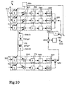
- a Rake receiver R1 including a searcher S8b, fingers f1-f5, a code generator CG, delaying means DM101, DM102, DM103, soft combiners AR1-AR3, and a bit decoder DEC.
- Each finger f1-f5 is arranged for receiving the wanted user data stream UDS over a corresponding propagation path P1-P5.
- the fingers f1-f5 are grouped into two sets of fingers.
- the first set comprises the first three fingers f1-f3 and will handle the first three power peaks PPK1-PPK3 of the delay profile CHIR in figure 7 .
- the second set of fingers f4, f5 includes the fourth and fifth finger f4, f5 and will handle the fourth and fifth power peaks PPK4, PPK5.
- Each finger f1-f5 includes a buffer B10 that receives and buffers the sampled signal stream r.
- the buffers B10 are arranged to delay a sequence of the received signal r to compensate for delay variations ⁇ 1 , ⁇ 2 , ⁇ 3 , ⁇ 4 , ⁇ 5 relative to the delay at the respective window WW1, WW2 end. Thereby, the propagation paths of the wanted user data stream are time aligned within each of the sets of fingers.
- the buffers B10 receives from the searchers the delays ⁇ 1 , ⁇ 2 , ⁇ 3 , ⁇ 4 , ⁇ 5 that are applied to the signal sequence r.
- the time aligned output signal r from the buffer B10 is in each finger f1-f5 multiplied with a delayed conjugate code stream PN D * in a multiplier M10.
- the conjugate code stream PN D * corresponds to the code stream PN D used for bandspreading the user data stream UDS before transmission and the code stream PN D distinguishes the radio channel RCH from other radio channels RCH.
- the delay applied to the conjugate code stream PN D * before the multiplication corresponds to the delay at the end of the respective window WW1, WW2 and is received by the delaying means DM101, DM102 from the searcher.
- each multiplier M10 The energy in the despread spectrum band NSB is collected in a following integrator ITR.
- the collected energy is fed to a demodulator DMD following.
- the demodulator DMD demodulates the non spread data stream and produces a stream of complex values to a value transformation unit REV arranged to transform the stream of complex values to a stream of real values.
- the output of the value transformation unit REV is also the output of the finger f1-f5 and on this output is thus generated a stream of real values.
- the soft combiners AR1, AR2 combine the streams of real values produced in respective set of fingers f1-f3, f4, f5.
- the third delaying means DM103 delays one of the combined real value streams to compensate for the difference in delay; thereby the two streams are correlated and thereafter combined in a third soft combiner AR3 and fed to a bit decoder DEC.
- the bit decoder DEC is arranged to make estimation on the original user data stream in the transmitter based on the input stream of real values.
- the bit decoder DEC generates on its output the estimated user data stream UDS .
- An advantage with the Rake receiver R1 of figure 10 is that time alignment at the beginning of the fingers need only be done with respect to the fingers of the set. Thereby the buffers B10 do not have to be as long and complex as in case where all the fingers f1-f5, i.e. both sets of fingers, had to be time aligned to each other. Instead, the output real value streams of the two set of fingers have to be time aligned before being combined. The real value output streams needs less buffering capacity than the sampled signal sequence r at the input of the fingers f1-f5. Thereby the Rake receiver R1 is less complex than a prior art Rake receiver.
- the fingers f1-f3 of the first set handles the propagation paths P1-P3 that are detected within the first window WW1 and the first window set WWS1 of the multiple window mode searcher S8b
- the second set of fingers f4, f5 handles the propagation paths detected within the second window WW2 and corresponding second window set WWS2 of the searcher S8b.
- the Rake receiver R1 could alternatively be arranged with a prior art searcher S1 instead of the multiple window searcher S8b.
- the inventive Rake receiver R1 can be arranged to assign an additional finger f2-f5 for receiving a propagation path whose power peak has arised over a certain value. Accordingly, a finger f1-f5 can also be released from a set arranged for receiving the user data stream if the corresponding power peak PPK1-PPK5 has decreased under a certain level.
- the Rake receiver can of cause be arranged with more than two sets of fingers f1-f5.
- the searcher S8a, S8b as described with reference to figures 8a and 8b has separate physical entities named window sets WWS1, WWS2 each arranged to handle a corresponding window.
- one physical entity can be arranged to handle several windows WW1, WW2 on time multiplex basis, i.e. its resources is divided in time and used for estimating the delay profile in separate windows WW1, WW2.
- One such common resource entity comprises the same parts connected as in any of the window sets WWS1, WWS2 that figures 8a and 8b shows. However, a difference is that the central processor controls the entity to work on time multiplex basis. Because the common resource entity has ability to estimate the delay profile CHIR in several windows WW1, WW2 the single entity is considered to comprise several window sets. These window sets of the one entity can be allocated to the same or to several radio links for estimating the delay spread CHIR.
Landscapes
- Engineering & Computer Science (AREA)
- Computer Networks & Wireless Communication (AREA)
- Signal Processing (AREA)
- Mobile Radio Communication Systems (AREA)
- Radio Transmission System (AREA)
- Circuits Of Receivers In General (AREA)
- Input Circuits Of Receivers And Coupling Of Receivers And Audio Equipment (AREA)
Claims (6)
- Funkkanalestimator (S8a, S8b) mit zwei oder mehr Fenstersätzen (WWS1, WWS2) zur Schätzung einer Funkkanalimpulsantwort (CHIR) in einem jeweiligen Fenster (WW1, WW2), dadurch gekennzeichnet, dass:die Fenstersätze dafür eingerichtet sind, alternativ zugeteilt zu werden, um die Kanalimpulsantwort auf getrennten Funkverbindungsstrecken oder auf derselben Funkverbindungstrecke zu schätzen, und wenn sie derselben Funkverbindungstrecke zugeteilt sind, die Fenster dafür eingerichtet sind, zeitlich aneinander anzugrenzen.
- Funkkanalestimator (S8a, S8b) nach Anspruch 1, der zur Verwendung in einem Codespreizspektrumsystem eingerichtet ist.
- Funkkanalestimator (S8a, S8b) nach Anspruch 1, wobei die Funkverbindungsstrecken durch einen jeweiligen Spreizcode unterscheidbar sind und der Funkkanalestimator ferner aufweist:Codeerzeugungsmittel (CG) zur Erzeugung der konjugierten Codeströme (PNP*) der Spreizcodes für die Fenstersätze (WWS1, WWS2),Steuermittel (CPU) zur Steuerung der Codeerzeugungsmittel, um einen ausgewählten konjugierten Codestrom für den jeweiligen Fenstersatz (WWS1, WWS2) zu erzeugen, und zur Steuerung der Position in der Zeit der Fenster (WW1, WW2).
- Funkkanalestimator nach Anspruch 3, wobei die Codeerzeugungsmittel gesteuert werden, um denselben konjugierten Codestrom für die zwei oder mehr Fenstersätze zu erzeugen, wenn diese derselben Funkverbindungsstrecke zugeteilt sind, und gesteuert werden, um getrennte konjugierte Codeströme zu erzeugen, wenn die zwei oder mehr Fenstersätze getrennten Funkverbindungsstrecken zugeteilt sind.
- Funkkanalestimator nach Anspruch 1, wobei jeder der Fenstersätze (WWS1, WWS2) aufweist:einen Puffer (B8) zur Pufferung einer Sequenz des empfangenen Signals (r),Verzögerungsmittel (DM1, DM2) zur unterschiedlichen Verzögerung des konjugierten Codestroms (PNP*), der vom Codegenerator (CG) empfangen wird,einen Multiplizierer (M81, M82) zum Multiplizieren des verzögerten konjugierten Codestroms vom Verzögerungsmittel mit der gepufferten Sequenz des empfangenen Signals (r) und dadurch Erzeugen einer Produktsequenz,Korrelationsdetektionsmittel (CD1, CD2) zur Schätzung der Kanalimpulsantwort innerhalb des Fensters (WW1, WW2) durch Detektieren der Leistung für jede aus einer Anzahl von Produktsequenzen, wobei die Verzögerung des konjugierten Codestroms für jede der Produktsequenzen geringfügig erhöht wird und die Verzögerungsveränderung (PHL) über alle Produktsequenzen der Länge (L1, L2) des Fensters (WW1, WW2) entspricht.
- RAKE-Empfänger mit einem Funkkanalestimator nach Anspruch 1.
Applications Claiming Priority (5)
| Application Number | Priority Date | Filing Date | Title |
|---|---|---|---|
| SE0001867A SE0001867D0 (sv) | 2000-05-18 | 2000-05-18 | Radio receiver and channel estimator |
| SE0001867 | 2000-05-18 | ||
| SE0003289 | 2000-09-15 | ||
| SE0003289A SE0003289D0 (sv) | 2000-05-18 | 2000-09-15 | Radio receiver and channel estimator |
| PCT/SE2001/001048 WO2001089109A2 (en) | 2000-05-18 | 2001-05-11 | Radio reciever and channel estimator |
Publications (2)
| Publication Number | Publication Date |
|---|---|
| EP1405428A2 EP1405428A2 (de) | 2004-04-07 |
| EP1405428B1 true EP1405428B1 (de) | 2009-09-30 |
Family
ID=26655114
Family Applications (1)
| Application Number | Title | Priority Date | Filing Date |
|---|---|---|---|
| EP01934731A Expired - Lifetime EP1405428B1 (de) | 2000-05-18 | 2001-05-11 | Funkempfänger und kanalabschätzer |
Country Status (8)
| Country | Link |
|---|---|
| US (1) | US7054353B2 (de) |
| EP (1) | EP1405428B1 (de) |
| AT (1) | ATE444601T1 (de) |
| AU (1) | AU2001260887A1 (de) |
| DE (1) | DE60140084D1 (de) |
| ES (1) | ES2334328T3 (de) |
| SE (1) | SE0003289D0 (de) |
| WO (1) | WO2001089109A2 (de) |
Families Citing this family (21)
| Publication number | Priority date | Publication date | Assignee | Title |
|---|---|---|---|---|
| GB2385498A (en) * | 2002-02-13 | 2003-08-20 | Pa Consulting Services | Adjustable baseband processing of telecommunications signals |
| FI20020953A0 (fi) | 2002-05-21 | 2002-05-21 | Nokia Corp | Kanavaestimointi hajaspektrijärjestelmässä |
| TWI255099B (en) * | 2003-03-05 | 2006-05-11 | Interdigital Tech Corp | Received communication signal processing methods and components for wireless communication equipment |
| WO2004107597A1 (en) * | 2003-05-27 | 2004-12-09 | Telefonaktiebolaget L M Ericsson (Publ) | Averaging a delay profile in a limited delay range |
| EP1482649B1 (de) * | 2003-05-27 | 2006-02-08 | Telefonaktiebolaget LM Ericsson (publ) | Positionierung eines Recherchegleitfensters zum Mehrwegsignalenempfäng |
| EP1482651A1 (de) | 2003-05-27 | 2004-12-01 | Telefonaktiebolaget LM Ericsson (publ) | Verfahren zur Ermittlung des durchschnittlichen Verzögerungsprofils in einem beschrankten Verzögerungsbereich |
| ATE373344T1 (de) * | 2003-06-13 | 2007-09-15 | Ericsson Telefon Ab L M | Verfahren und vorrichtung zur einstellung eines mehrwegsuchfensters |
| WO2004112269A1 (en) * | 2003-06-13 | 2004-12-23 | Telefonaktiebolaget Lm Ericsson (Publ) | Positioning a multipath search window |
| JP4145240B2 (ja) * | 2003-12-26 | 2008-09-03 | 三洋電機株式会社 | ダイバーシチ受信方法および装置 |
| US7340014B2 (en) * | 2003-12-31 | 2008-03-04 | Intel Corporation | Apparatus and method of multi-user detection |
| GB0410617D0 (en) * | 2004-05-12 | 2004-06-16 | Ttp Communications Ltd | Path searching |
| US7372895B2 (en) * | 2004-12-08 | 2008-05-13 | Telefonaktiebolaget Lm Ericsson (Publ) | Method of and system for delay estimation with minimized finger allocation |
| CN101084633B (zh) * | 2004-12-17 | 2011-05-18 | 华为技术有限公司 | 多径搜索器、细化处理单元及进行波达方向估计的方法 |
| CN1863021B (zh) * | 2005-05-13 | 2010-04-28 | 上海原动力通信科技有限公司 | 无线通信系统中的码道分配方法和多用户检测方法 |
| US8265209B2 (en) * | 2005-10-28 | 2012-09-11 | Qualcomm Incorporated | Method and apparatus for channel and noise estimation |
| CA2633060A1 (en) | 2005-12-28 | 2007-07-19 | Elektrobit System Test Oy | Method, apparatus, analyser and computer program of searching for propagation paths |
| CN100420329C (zh) * | 2006-08-09 | 2008-09-17 | 华为技术有限公司 | 一种上行专用物理信道搜索方法及装置 |
| US7839917B2 (en) * | 2006-09-18 | 2010-11-23 | Mediatek Inc. | Receiver of a CDMA system with a path alignment circuit |
| US8891698B2 (en) * | 2007-12-03 | 2014-11-18 | St-Ericsson Sa | First significant path detection |
| KR101529627B1 (ko) * | 2008-12-23 | 2015-06-29 | 삼성전자 주식회사 | 이동통신 시스템의 채널 추정장치 및 방법 |
| KR101608744B1 (ko) * | 2009-06-04 | 2016-04-04 | 삼성전자주식회사 | 이동통신 수신기의 채널 추정을 위한 타임 트래킹 방법 및 장치 |
Family Cites Families (13)
| Publication number | Priority date | Publication date | Assignee | Title |
|---|---|---|---|---|
| FI946184A0 (fi) * | 1993-06-02 | 1994-12-30 | Roke Manor Research | Laite käytettäväksi laitteistossa, jolla muodostetaan digitaalinen radioyhteys kiinteän radioyksikön ja matkaviestimen välille |
| US5530716A (en) * | 1994-06-30 | 1996-06-25 | Motorola, Inc. | Method and apparatus for identifying a coded communication signal |
| AU687228B2 (en) * | 1994-07-29 | 1998-02-19 | Qualcomm Incorporated | Method and apparatus for performing code acquisition in a CDMA communications system |
| US5710768A (en) * | 1994-09-30 | 1998-01-20 | Qualcomm Incorporated | Method of searching for a bursty signal |
| US6049564A (en) * | 1997-04-28 | 2000-04-11 | Northern Telecom Limited | Method and apparatus for configuring PN-offsets for a non-uniform CDMA cellular network |
| US6215762B1 (en) * | 1997-07-22 | 2001-04-10 | Ericsson Inc. | Communication system and method with orthogonal block encoding |
| US6185199B1 (en) * | 1997-07-23 | 2001-02-06 | Qualcomm Inc. | Method and apparatus for data transmission using time gated frequency division duplexing |
| US6526029B1 (en) * | 1998-04-24 | 2003-02-25 | Lucent Technologies Inc. | Search scheme for receivers in mobile communication systems |
| US6370397B1 (en) * | 1998-05-01 | 2002-04-09 | Telefonaktiebolaget Lm Ericsson (Publ) | Search window delay tracking in code division multiple access communication systems |
| US6731622B1 (en) * | 1998-05-01 | 2004-05-04 | Telefonaktiebolaget Lm Ericsson (Publ) | Multipath propagation delay determining means using periodically inserted pilot symbols |
| JPH11331037A (ja) * | 1998-05-14 | 1999-11-30 | Tokimec Inc | スペクトラム拡散無線通信装置 |
| JP3031350B2 (ja) * | 1998-09-14 | 2000-04-10 | 日本電気株式会社 | スペクトラム拡散復調装置および方法 |
| US6377615B1 (en) * | 1999-09-30 | 2002-04-23 | Ericsson Inc. | Apparatus and methods for receiving information using variable length accumulation searchers |
-
2000
- 2000-09-15 SE SE0003289A patent/SE0003289D0/xx unknown
-
2001
- 2001-05-11 WO PCT/SE2001/001048 patent/WO2001089109A2/en not_active Ceased
- 2001-05-11 EP EP01934731A patent/EP1405428B1/de not_active Expired - Lifetime
- 2001-05-11 AT AT01934731T patent/ATE444601T1/de not_active IP Right Cessation
- 2001-05-11 DE DE60140084T patent/DE60140084D1/de not_active Expired - Lifetime
- 2001-05-11 AU AU2001260887A patent/AU2001260887A1/en not_active Abandoned
- 2001-05-11 ES ES01934731T patent/ES2334328T3/es not_active Expired - Lifetime
- 2001-05-17 US US09/858,633 patent/US7054353B2/en not_active Expired - Fee Related
Also Published As
| Publication number | Publication date |
|---|---|
| WO2001089109A3 (en) | 2003-12-31 |
| ATE444601T1 (de) | 2009-10-15 |
| DE60140084D1 (de) | 2009-11-12 |
| US20010046221A1 (en) | 2001-11-29 |
| EP1405428A2 (de) | 2004-04-07 |
| US7054353B2 (en) | 2006-05-30 |
| SE0003289D0 (sv) | 2000-09-15 |
| WO2001089109A2 (en) | 2001-11-22 |
| ES2334328T3 (es) | 2010-03-09 |
| AU2001260887A1 (en) | 2001-11-26 |
Similar Documents
| Publication | Publication Date | Title |
|---|---|---|
| EP1405428B1 (de) | Funkempfänger und kanalabschätzer | |
| US7061967B2 (en) | Multipath channel tap delay estimation in a CDMA spread spectrum receiver | |
| EP0691754A2 (de) | Dynamische Kontrolle von Suche und Nachführung der Korrelatoren einer RAKE Empfänger | |
| JP3159378B2 (ja) | スペクトル拡散通信方式 | |
| JP4280423B2 (ja) | 複数のレークブランチがトラッキング装置を共有するcdma受信機 | |
| JPH10190528A (ja) | スペクトル拡散受信機 | |
| JP2001519116A (ja) | 固定分割率および可変拡散コード長を利用する多重率直接シーケンスアーキテクチュア | |
| JPH11215053A (ja) | 移動通信における速度推定装置および方法 | |
| EP1279239B1 (de) | Signalangepasstes filter und empfänger für mobiles funkkommunikationssystem | |
| KR100361408B1 (ko) | Cdma 통신을 위한 동기포착회로 | |
| JPH09181704A (ja) | Cdmaマルチパス・サーチ方法及びcdma信号受信装置 | |
| KR100504360B1 (ko) | 수신기 및 수신 방법 | |
| EP1350338B1 (de) | Zeitnachführung in einer unvernachlässigbaren mehrwegdistanzumgebung | |
| JP3869674B2 (ja) | スペクトラム拡散通信用スライディングコリレータ | |
| JP2991236B1 (ja) | 直接拡散受信デ―タの誤り推定装置および直接拡散受信装置 | |
| KR101023376B1 (ko) | 레이크 수신기, 핑거, 신호 보상 시스템, 휴대형 유닛, 네트워크 유닛, 신호 보상 방법 및 컴퓨터 판독가능 저장 매체 | |
| JP2941651B2 (ja) | 移動通信方式 | |
| WO2002005446A1 (en) | Rake receiver and method related to a rake receiver | |
| JP3147112B2 (ja) | 直接拡散受信装置 | |
| JP2002118492A (ja) | 逆拡散回路 | |
| JP2877243B2 (ja) | スペクトラム拡散通信用受信機 | |
| WO2002060080A1 (en) | A rake receiver | |
| KR100319751B1 (ko) | 공간-시간 다이버시티 수신기용 채널 예측장치 및 그 방법 | |
| JP3587207B2 (ja) | Cdma受信装置及びその方法 | |
| JP2001251214A (ja) | 同期追従装置 |
Legal Events
| Date | Code | Title | Description |
|---|---|---|---|
| PUAI | Public reference made under article 153(3) epc to a published international application that has entered the european phase |
Free format text: ORIGINAL CODE: 0009012 |
|
| 17P | Request for examination filed |
Effective date: 20020912 |
|
| AK | Designated contracting states |
Kind code of ref document: A2 Designated state(s): AT BE CH CY DE DK ES FI FR GB GR IE IT LI LU MC NL PT SE TR |
|
| AX | Request for extension of the european patent |
Extension state: AL LT LV MK RO SI |
|
| RAP1 | Party data changed (applicant data changed or rights of an application transferred) |
Owner name: TELEFONAKTIEBOLAGET LM ERICSSON (PUBL) |
|
| 17Q | First examination report despatched |
Effective date: 20061215 |
|
| GRAP | Despatch of communication of intention to grant a patent |
Free format text: ORIGINAL CODE: EPIDOSNIGR1 |
|
| DAX | Request for extension of the european patent (deleted) | ||
| GRAS | Grant fee paid |
Free format text: ORIGINAL CODE: EPIDOSNIGR3 |
|
| GRAA | (expected) grant |
Free format text: ORIGINAL CODE: 0009210 |
|
| AK | Designated contracting states |
Kind code of ref document: B1 Designated state(s): AT BE CH CY DE DK ES FI FR GB GR IE IT LI LU MC NL PT SE TR |
|
| REG | Reference to a national code |
Ref country code: GB Ref legal event code: FG4D Ref country code: CH Ref legal event code: EP |
|
| REG | Reference to a national code |
Ref country code: IE Ref legal event code: FG4D |
|
| REF | Corresponds to: |
Ref document number: 60140084 Country of ref document: DE Date of ref document: 20091112 Kind code of ref document: P |
|
| PG25 | Lapsed in a contracting state [announced via postgrant information from national office to epo] |
Ref country code: SE Free format text: LAPSE BECAUSE OF FAILURE TO SUBMIT A TRANSLATION OF THE DESCRIPTION OR TO PAY THE FEE WITHIN THE PRESCRIBED TIME-LIMIT Effective date: 20090930 Ref country code: FI Free format text: LAPSE BECAUSE OF FAILURE TO SUBMIT A TRANSLATION OF THE DESCRIPTION OR TO PAY THE FEE WITHIN THE PRESCRIBED TIME-LIMIT Effective date: 20090930 |
|
| NLV1 | Nl: lapsed or annulled due to failure to fulfill the requirements of art. 29p and 29m of the patents act | ||
| REG | Reference to a national code |
Ref country code: ES Ref legal event code: FG2A Ref document number: 2334328 Country of ref document: ES Kind code of ref document: T3 |
|
| PG25 | Lapsed in a contracting state [announced via postgrant information from national office to epo] |
Ref country code: PT Free format text: LAPSE BECAUSE OF FAILURE TO SUBMIT A TRANSLATION OF THE DESCRIPTION OR TO PAY THE FEE WITHIN THE PRESCRIBED TIME-LIMIT Effective date: 20100201 |
|
| PG25 | Lapsed in a contracting state [announced via postgrant information from national office to epo] |
Ref country code: CY Free format text: LAPSE BECAUSE OF FAILURE TO SUBMIT A TRANSLATION OF THE DESCRIPTION OR TO PAY THE FEE WITHIN THE PRESCRIBED TIME-LIMIT Effective date: 20090930 |
|
| PG25 | Lapsed in a contracting state [announced via postgrant information from national office to epo] |
Ref country code: BE Free format text: LAPSE BECAUSE OF FAILURE TO SUBMIT A TRANSLATION OF THE DESCRIPTION OR TO PAY THE FEE WITHIN THE PRESCRIBED TIME-LIMIT Effective date: 20090930 Ref country code: AT Free format text: LAPSE BECAUSE OF FAILURE TO SUBMIT A TRANSLATION OF THE DESCRIPTION OR TO PAY THE FEE WITHIN THE PRESCRIBED TIME-LIMIT Effective date: 20090930 |
|
| PG25 | Lapsed in a contracting state [announced via postgrant information from national office to epo] |
Ref country code: DK Free format text: LAPSE BECAUSE OF FAILURE TO SUBMIT A TRANSLATION OF THE DESCRIPTION OR TO PAY THE FEE WITHIN THE PRESCRIBED TIME-LIMIT Effective date: 20090930 Ref country code: NL Free format text: LAPSE BECAUSE OF FAILURE TO SUBMIT A TRANSLATION OF THE DESCRIPTION OR TO PAY THE FEE WITHIN THE PRESCRIBED TIME-LIMIT Effective date: 20090930 |
|
| PLBE | No opposition filed within time limit |
Free format text: ORIGINAL CODE: 0009261 |
|
| STAA | Information on the status of an ep patent application or granted ep patent |
Free format text: STATUS: NO OPPOSITION FILED WITHIN TIME LIMIT |
|
| 26N | No opposition filed |
Effective date: 20100701 |
|
| PG25 | Lapsed in a contracting state [announced via postgrant information from national office to epo] |
Ref country code: GR Free format text: LAPSE BECAUSE OF FAILURE TO SUBMIT A TRANSLATION OF THE DESCRIPTION OR TO PAY THE FEE WITHIN THE PRESCRIBED TIME-LIMIT Effective date: 20091231 |
|
| PG25 | Lapsed in a contracting state [announced via postgrant information from national office to epo] |
Ref country code: MC Free format text: LAPSE BECAUSE OF NON-PAYMENT OF DUE FEES Effective date: 20100531 |
|
| REG | Reference to a national code |
Ref country code: CH Ref legal event code: PL |
|
| REG | Reference to a national code |
Ref country code: FR Ref legal event code: ST Effective date: 20110131 |
|
| PG25 | Lapsed in a contracting state [announced via postgrant information from national office to epo] |
Ref country code: LI Free format text: LAPSE BECAUSE OF NON-PAYMENT OF DUE FEES Effective date: 20100531 Ref country code: CH Free format text: LAPSE BECAUSE OF NON-PAYMENT OF DUE FEES Effective date: 20100531 |
|
| PG25 | Lapsed in a contracting state [announced via postgrant information from national office to epo] |
Ref country code: IT Free format text: LAPSE BECAUSE OF FAILURE TO SUBMIT A TRANSLATION OF THE DESCRIPTION OR TO PAY THE FEE WITHIN THE PRESCRIBED TIME-LIMIT Effective date: 20090930 |
|
| PG25 | Lapsed in a contracting state [announced via postgrant information from national office to epo] |
Ref country code: IE Free format text: LAPSE BECAUSE OF NON-PAYMENT OF DUE FEES Effective date: 20100511 |
|
| PG25 | Lapsed in a contracting state [announced via postgrant information from national office to epo] |
Ref country code: FR Free format text: LAPSE BECAUSE OF NON-PAYMENT OF DUE FEES Effective date: 20100531 |
|
| PG25 | Lapsed in a contracting state [announced via postgrant information from national office to epo] |
Ref country code: LU Free format text: LAPSE BECAUSE OF NON-PAYMENT OF DUE FEES Effective date: 20100511 |
|
| PG25 | Lapsed in a contracting state [announced via postgrant information from national office to epo] |
Ref country code: TR Free format text: LAPSE BECAUSE OF FAILURE TO SUBMIT A TRANSLATION OF THE DESCRIPTION OR TO PAY THE FEE WITHIN THE PRESCRIBED TIME-LIMIT Effective date: 20090930 |
|
| PGFP | Annual fee paid to national office [announced via postgrant information from national office to epo] |
Ref country code: ES Payment date: 20150526 Year of fee payment: 15 Ref country code: DE Payment date: 20150528 Year of fee payment: 15 Ref country code: GB Payment date: 20150527 Year of fee payment: 15 |
|
| REG | Reference to a national code |
Ref country code: DE Ref legal event code: R119 Ref document number: 60140084 Country of ref document: DE |
|
| GBPC | Gb: european patent ceased through non-payment of renewal fee |
Effective date: 20160511 |
|
| PG25 | Lapsed in a contracting state [announced via postgrant information from national office to epo] |
Ref country code: DE Free format text: LAPSE BECAUSE OF NON-PAYMENT OF DUE FEES Effective date: 20161201 |
|
| PG25 | Lapsed in a contracting state [announced via postgrant information from national office to epo] |
Ref country code: GB Free format text: LAPSE BECAUSE OF NON-PAYMENT OF DUE FEES Effective date: 20160511 |
|
| PG25 | Lapsed in a contracting state [announced via postgrant information from national office to epo] |
Ref country code: ES Free format text: LAPSE BECAUSE OF NON-PAYMENT OF DUE FEES Effective date: 20160512 |
|
| REG | Reference to a national code |
Ref country code: ES Ref legal event code: FD2A Effective date: 20181203 |