EP1404483B1 - Improvements in or relating to solders - Google Patents
Improvements in or relating to solders Download PDFInfo
- Publication number
- EP1404483B1 EP1404483B1 EP02716141A EP02716141A EP1404483B1 EP 1404483 B1 EP1404483 B1 EP 1404483B1 EP 02716141 A EP02716141 A EP 02716141A EP 02716141 A EP02716141 A EP 02716141A EP 1404483 B1 EP1404483 B1 EP 1404483B1
- Authority
- EP
- European Patent Office
- Prior art keywords
- solder
- lead
- solders
- free
- copper
- Prior art date
- Legal status (The legal status is an assumption and is not a legal conclusion. Google has not performed a legal analysis and makes no representation as to the accuracy of the status listed.)
- Expired - Lifetime
Links
- 229910000679 solder Inorganic materials 0.000 title claims abstract description 196
- 229910052802 copper Inorganic materials 0.000 claims abstract description 51
- 239000010949 copper Substances 0.000 claims abstract description 51
- 229910052718 tin Inorganic materials 0.000 claims abstract description 50
- RYGMFSIKBFXOCR-UHFFFAOYSA-N Copper Chemical compound [Cu] RYGMFSIKBFXOCR-UHFFFAOYSA-N 0.000 claims abstract description 37
- 229910052709 silver Inorganic materials 0.000 claims abstract description 35
- 229910052738 indium Inorganic materials 0.000 claims abstract description 25
- ATJFFYVFTNAWJD-UHFFFAOYSA-N Tin Chemical compound [Sn] ATJFFYVFTNAWJD-UHFFFAOYSA-N 0.000 claims abstract description 22
- APFVFJFRJDLVQX-UHFFFAOYSA-N indium atom Chemical compound [In] APFVFJFRJDLVQX-UHFFFAOYSA-N 0.000 claims abstract description 19
- 239000004332 silver Substances 0.000 claims abstract description 19
- 238000000034 method Methods 0.000 claims abstract description 17
- 238000005476 soldering Methods 0.000 claims abstract description 16
- BHEPBYXIRTUNPN-UHFFFAOYSA-N hydridophosphorus(.) (triplet) Chemical compound [PH] BHEPBYXIRTUNPN-UHFFFAOYSA-N 0.000 claims description 9
- BQCADISMDOOEFD-UHFFFAOYSA-N Silver Chemical compound [Ag] BQCADISMDOOEFD-UHFFFAOYSA-N 0.000 claims description 5
- 239000000654 additive Substances 0.000 abstract 1
- 230000000996 additive effect Effects 0.000 abstract 1
- 239000003963 antioxidant agent Substances 0.000 abstract 1
- 230000003078 antioxidant effect Effects 0.000 abstract 1
- 235000006708 antioxidants Nutrition 0.000 abstract 1
- 238000012360 testing method Methods 0.000 description 36
- 238000009736 wetting Methods 0.000 description 18
- 229910052797 bismuth Inorganic materials 0.000 description 11
- 239000000203 mixture Substances 0.000 description 11
- 229910045601 alloy Inorganic materials 0.000 description 10
- 239000000956 alloy Substances 0.000 description 10
- 238000000576 coating method Methods 0.000 description 10
- 238000004090 dissolution Methods 0.000 description 9
- PXHVJJICTQNCMI-UHFFFAOYSA-N Nickel Chemical compound [Ni] PXHVJJICTQNCMI-UHFFFAOYSA-N 0.000 description 8
- 239000010931 gold Substances 0.000 description 5
- 229910052745 lead Inorganic materials 0.000 description 4
- 238000004519 manufacturing process Methods 0.000 description 4
- 230000000704 physical effect Effects 0.000 description 4
- 229910052737 gold Inorganic materials 0.000 description 3
- 238000007654 immersion Methods 0.000 description 3
- 239000000463 material Substances 0.000 description 3
- 238000005259 measurement Methods 0.000 description 3
- 229910052759 nickel Inorganic materials 0.000 description 3
- 229910052733 gallium Inorganic materials 0.000 description 2
- 238000001000 micrograph Methods 0.000 description 2
- 239000000758 substrate Substances 0.000 description 2
- 230000006978 adaptation Effects 0.000 description 1
- 239000000853 adhesive Substances 0.000 description 1
- 230000001070 adhesive effect Effects 0.000 description 1
- 230000004075 alteration Effects 0.000 description 1
- 239000011248 coating agent Substances 0.000 description 1
- 239000000470 constituent Substances 0.000 description 1
- 230000007547 defect Effects 0.000 description 1
- 238000007598 dipping method Methods 0.000 description 1
- 238000006073 displacement reaction Methods 0.000 description 1
- 230000008030 elimination Effects 0.000 description 1
- 238000003379 elimination reaction Methods 0.000 description 1
- 230000007613 environmental effect Effects 0.000 description 1
- 230000005484 gravity Effects 0.000 description 1
- 238000009616 inductively coupled plasma Methods 0.000 description 1
- 238000002844 melting Methods 0.000 description 1
- 230000008018 melting Effects 0.000 description 1
- 229920000642 polymer Polymers 0.000 description 1
- 239000000126 substance Substances 0.000 description 1
Images


Classifications
-
- B—PERFORMING OPERATIONS; TRANSPORTING
- B23—MACHINE TOOLS; METAL-WORKING NOT OTHERWISE PROVIDED FOR
- B23K—SOLDERING OR UNSOLDERING; WELDING; CLADDING OR PLATING BY SOLDERING OR WELDING; CUTTING BY APPLYING HEAT LOCALLY, e.g. FLAME CUTTING; WORKING BY LASER BEAM
- B23K35/00—Rods, electrodes, materials, or media, for use in soldering, welding, or cutting
- B23K35/22—Rods, electrodes, materials, or media, for use in soldering, welding, or cutting characterised by the composition or nature of the material
- B23K35/24—Selection of soldering or welding materials proper
- B23K35/26—Selection of soldering or welding materials proper with the principal constituent melting at less than 400 degrees C
- B23K35/262—Sn as the principal constituent
Definitions
- THIS INVENTION relates to solders, and in particular, to solders which are substantially lead-free.
- solders contain lead as a major constituent thereof. Such solders often have desirable physical properties, and the use of lead-containing solders is widespread throughout several industries, including those concerned with the production of printed circuit boards. For example, a solder containing a 63% tin and 37% lead is commonly used in wave-soldering processes.
- lead-free solders Previous attempts to formulate lead-free solders have met with limited success. Conventional lead-free solders generally have undesirable physical properties, including poor wetting properties, low fluidity, poor compatibility with existing component coatings and excessive dressing. A particular problem which has been recognised in the use of lead-free solders is the issue of fillet lifting, where a fillet of solder at the edge of a through-plated hole in a printed circuit board tends to separate from the underlying material, for example, a nickel/gold coating. Another problem is the fact that lead-free solders tend to have a high dissolution rate for copper, so that copper is leached into the lead-free solder from components and circuit boards in contact with the solder.
- Examples of lead-free tin-based solders comprising silver, copper, indium are disclosed in WO 97 09 455 A, WO 97 43 456 A or JP 09155586 A.
- the invention provides a substantially lead-free solder which comprises 91.3% tin, 4.2% silver, 4.0% indium and 0.5% copper.
- the solder comprises 91.39% tin, 4.1% silver, 4.0% indium, 0.5% copper and 0.01% phosphorous.
- a method of preparing a substantially lead-free solder comprising the step of mixing tin, silver, indium and copper such that: the proportion of tin in the solder is 91.3%; the proportion of silver in the solder is 4.2%; the proportion of indium in the solder is 4.0%; and the proportion of copper in the solder is 0.5%.
- Another method of preparing a solder in accordance with the invention comprises the step of mixing tin, silver, indium, copper and phosphorous such that: the proportion of tin in the solder is 91.39%; the proportion of silver in the solder is 4.1%; the proportion of indium in the solder is 4.0%; the proportion of copper in the solder is 0.5%; and the proportion of phosphorous in the solder is 0.01%.
- a further aspect of the present invention provides a method of soldering, comprising the step of using a solder comprising 91.3% tin, 4.2% silver, 4.0% indium and 0.5% copper.
- the method comprises the step of using a solder comprising 91.39% tin, 4.1% silver, 4.0% indium, 0.5% copper and 0.01% phosphorous.
- the method comprises the step of wave-soldering using the substantially lead-free solder.
- solder embodying the present invention possesses significantly improved properties when compared with known lead-free solders. Indeed the properties of solders embodying the present invention are comparable to conventional solders containing lead as regards wettability, fluidity, compatibility with existing component coatings, fillet lifting, copper dissolution rate and dressing.
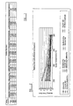
- the first test concerned the wetability of a sample of the solder embodying the present invention, as compared to samples of a selection of known solders, namely eight existing lead-free solders and a conventional lead-containing solder.
- a first aspect of the first test comprised the measurement of the wetting time, based on the ANSI/J Std-003 standard, for the solders under consideration at a variety of temperatures ranging from 235° C to 265° C.
- a specimen of copper was immersed in a quantity of each molten solder.
- a sensitive force measuring device was connected to the copper specimen, and arranged so that vertical forces on the specimen could be measured and recorded.
- the variation in the vertical force upon the copper specimen during immersion thereof in the molten solders is due to two main factors.
- the first of these, the buoyancy force arises from the upward force exerted on the specimen due to the displacement of solder, which is equal to the weight of solder displaced by the specimen. Since the volume of the part of the specimen that was immersed in the solder, and the density of the solder, are known, this upward force can be calculated and taken into account.
- the second factor is a force acting on the specimen due to the change in contact angle between the surface of the solder and the surface of the specimen.
- the wetting time in each particular case was defined as the time taken for the wetting force acting on the specimen to be equal to zero.
- the solder embodying the present invention exhibited a wetting time, at each of the temperatures, that was comparable to that displayed by the conventional lead-containing solder.
- the solder embodying the present invention exhibited a wetting time which was generally lower than that displayed by any of the other lead-free solders.
- the wetting time is a measure of the rapidity with which a solder adheres to a substance, and clearly a low wetting time is a desirable property for a solder.
- the solder embodying the present invention performed better overall in the first aspect of the first test than any of the existing lead-free solders.
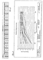
- a second aspect of the first test comprised the measurement of the maximum wetting force at 2.0 seconds after immersion of the specimen in the respective solders.
- the wetting force is, as described above, the adhesive force between the solder and the specimen.
- the wetting force provides a useful indication of the strength with which a solder binds to a substrate, and a high wetting force is a desirable property for a solder.
- solder embodying the present invention exhibits very similar properties, with regard to wettability, to the conventional lead-containing solder. Clearly, this similarity in physical properties renders the solder embodying the present invention suitable for use as a replacement for the conventional lead-containing solder.
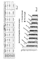
- a second test compared the mechanical properties of the solder of the present invention with the mechanical properties of a conventional lead-containing solder.
- various mechanical tests were carried out in accordance with the ASTM standard to compare the properties of ALLOY 349, the solder embodying the present invention, with a conventional lead-containing solder with the composition 63%Sn/37%Pb and seven other existing lead-free solders, with the following compositions:
- a first aspect of this second test involved determining the melting temperature, the coefficient of thermal expansion (CTE) and the specific gravity (SG) of the solders under test.
- CTE coefficient of thermal expansion
- SG specific gravity
- the ALLOY 349 solder of the present invention proved to have a thermal expansion co-efficient which is very close to the conventional lead-containing solder, so that any fear of incompatibility between the invention and existing components and boards is significantly reduced.
- a second aspect of the second test involved measuring the tensile strength, load at maximum load, yield strength and Young's Modulus of the various solders. The results of these tests are expressed in full in the table of Figure 7, while Figure 8 graphically shows the tensile strength and yield strength of each of the alloys.
- Figures 9, 10A and 10B show the results in tabulated form.
- Figures 10A and 10B show micrographs, on two different scales, of fillet joints formed using the ALLOY 349 solder embodying the present invention on Ni/Au and OSP coatings, respectively. These results clearly indicate that the use of a solder embodying the present invention enables the elimination of fillet lifting defects in the context of OSP and nickel/gold coated through-holes in printed circuit boards.
- a fourth test was carried out to compare the copper dissolution rate in a lead-free solder embodying the present invention with a conventional lead-containing solder (63%Sn/37%Pb) and three existing lead-free solders as follows;
- a fifth test was concerned with the suitability of the solder of the present invention for use in a wave-soldering machine.
- a circuit board is held just above the surface of a quantity of molten solder in a pot.
- a wave is then caused to propagate across the surface of the molten solder, of sufficient amplitude that the crest of the wave comes into contact with the surface of the circuit board.
- the wave is as wide as the circuit board (or the portions thereof that require soldering), and as the wave propagates across the surface of the molten solder all parts of the downward-facing surface of the circuit board are contacted with molten solder.
- a fifth test was carried out to determine the extent of drossing when using the ALLOY 349 solder embodying the present invention compared with the conventional 63%Sn/37%Pb solder and with three other existing lead-free solders, as follows:
- the solder being tested was used in a pot of molten solder in a simulated conventional wave-soldering machine. No alteration of the machine was made to accommodate the use of the solder and the wave-soldering machine was used to solder circuit boards in the same way as for a conventional tin/lead solder.
- the wave-soldering machine was operated in a normal air environment at a pot temperature of 245° C, with the boards being conveyed over the surface of the pot at a speed of 1.4 to 1.8m/min. At the end of each of four successive 15 minute periods of operation, the dross in the pot was removed and weighed to determine the amount of dross produced by the wave-soldering process in each period.
- the present invention provides a lead-free solder that is very suitable for use as a direct replacement for conventional lead-containing solders, due to the comparable characteristics of wettability, fluidity, compatibility with existing component coatings, fillet lifting and drossing exhibited by the solder of the present invention.
Landscapes
- Engineering & Computer Science (AREA)
- Mechanical Engineering (AREA)
- Electric Connection Of Electric Components To Printed Circuits (AREA)
- Silicates, Zeolites, And Molecular Sieves (AREA)
- Parts Printed On Printed Circuit Boards (AREA)
- Glass Compositions (AREA)
- Thermally Insulated Containers For Foods (AREA)
- Nonmetallic Welding Materials (AREA)
- Lining Or Joining Of Plastics Or The Like (AREA)
- Details Of Resistors (AREA)
Abstract
Description
Claims (7)
- A substantially lead-free solder, comprising in weight %
91.3% tin, 4.2% silver, 4.0% indium and 0.5% copper. - A method of preparing a substantially lead-free solder, comprising the step of mixing tin, silver, indium and copper such that the proportion of tin is 91.3%, the proportion of silver is 4.2%, the proportion of indium is 4.0% and the proportion of copper is 0.5% said proportions being expressed in weight %.
- A method of soldering, comprising the step of using a substantially lead-free solder comprising in weight % 91.3% tin, 4.2% silver, 4.0% indium and 0.5% copper.
- A substantially lead-free solder comprising in weight % 91.39% tin, 4.1% silver, 4.0% indium, 0.5% copper and 0.01% phosphorous.
- A method of preparing a substantially lead-free solder, comprising the step of mixing tin, silver, indium, copper and phosphorous such that the proportion of tin is 91.39%, the proportion of silver is 4.1%, the proportion of indium is 4.0%, the proportion of copper is 0.5% and the proportion of phosphorous is 0.01%, said proportions being expressed in weight %.
- A method of soldering, comprising the step of using a substantially lead-free solder comprising in weight % 91.39% tin, 4.1% silver, 4.0% indium, 0.5% copper and 0.01% phosphorous.
- A method according to Claim 3 or 6, comprising the step of wave-soldering using the substantially lead-free solder.
Applications Claiming Priority (3)
| Application Number | Priority Date | Filing Date | Title |
|---|---|---|---|
| SG200104071-6A SG139507A1 (en) | 2001-07-09 | 2001-07-09 | Improvements in or relating to solders |
| SG200104071 | 2001-07-09 | ||
| PCT/GB2002/000259 WO2003006200A1 (en) | 2001-07-09 | 2002-01-22 | Improvements in or relating to solders |
Publications (2)
| Publication Number | Publication Date |
|---|---|
| EP1404483A1 EP1404483A1 (en) | 2004-04-07 |
| EP1404483B1 true EP1404483B1 (en) | 2004-10-06 |
Family
ID=20430801
Family Applications (1)
| Application Number | Title | Priority Date | Filing Date |
|---|---|---|---|
| EP02716141A Expired - Lifetime EP1404483B1 (en) | 2001-07-09 | 2002-01-22 | Improvements in or relating to solders |
Country Status (23)
| Country | Link |
|---|---|
| US (1) | US6843862B2 (en) |
| EP (1) | EP1404483B1 (en) |
| JP (1) | JP3795797B2 (en) |
| CN (1) | CN1235717C (en) |
| AT (1) | ATE278502T1 (en) |
| AU (1) | AU2002226534B2 (en) |
| BR (1) | BR0210970A (en) |
| CZ (1) | CZ303793B6 (en) |
| DE (1) | DE60201542T2 (en) |
| DK (1) | DK1404483T3 (en) |
| ES (1) | ES2230477T3 (en) |
| HK (1) | HK1053278A1 (en) |
| HU (1) | HU229014B1 (en) |
| MX (1) | MXPA04000229A (en) |
| MY (1) | MY123567A (en) |
| NO (1) | NO337878B1 (en) |
| NZ (1) | NZ530220A (en) |
| PL (1) | PL201507B1 (en) |
| PT (1) | PT1404483E (en) |
| RU (1) | RU2268126C2 (en) |
| SG (1) | SG139507A1 (en) |
| TW (1) | TW592869B (en) |
| WO (1) | WO2003006200A1 (en) |
Families Citing this family (39)
| Publication number | Priority date | Publication date | Assignee | Title |
|---|---|---|---|---|
| US8918073B2 (en) * | 2002-03-28 | 2014-12-23 | Telecommunication Systems, Inc. | Wireless telecommunications location based services scheme selection |
| US9154906B2 (en) | 2002-03-28 | 2015-10-06 | Telecommunication Systems, Inc. | Area watcher for wireless network |
| JP2004179618A (en) * | 2002-10-04 | 2004-06-24 | Sharp Corp | Solar cell, its manufacturing method, interconnector for solar cell, string, and module |
| JP2004146464A (en) * | 2002-10-22 | 2004-05-20 | Sharp Corp | Solar cell, its manufacturing method, inter-connector therefor, string, and module |
| US20040187976A1 (en) * | 2003-03-31 | 2004-09-30 | Fay Hua | Phase change lead-free super plastic solders |
| US7111771B2 (en) * | 2003-03-31 | 2006-09-26 | Intel Corporation | Solders with surfactant-refined grain sizes, solder bumps made thereof, and methods of making same |
| US7282175B2 (en) * | 2003-04-17 | 2007-10-16 | Senju Metal Industry Co., Ltd. | Lead-free solder |
| EP1679149B1 (en) * | 2003-10-07 | 2012-05-02 | Senju Metal Industry Co., Ltd. | Lead-free solder ball |
| US20050100474A1 (en) * | 2003-11-06 | 2005-05-12 | Benlih Huang | Anti-tombstoning lead free alloys for surface mount reflow soldering |
| US20080126535A1 (en) * | 2006-11-28 | 2008-05-29 | Yinjun Zhu | User plane location services over session initiation protocol (SIP) |
| EP1560272B1 (en) * | 2004-01-29 | 2016-04-27 | Panasonic Intellectual Property Management Co., Ltd. | Solar cell module |
| US8961709B1 (en) | 2004-03-09 | 2015-02-24 | Senju Metal Industry Co., Ltd. | Solder paste |
| US7223695B2 (en) * | 2004-09-30 | 2007-05-29 | Intel Corporation | Methods to deposit metal alloy barrier layers |
| US6985105B1 (en) * | 2004-10-15 | 2006-01-10 | Telecommunication Systems, Inc. | Culled satellite ephemeris information based on limiting a span of an inverted cone for locating satellite in-range determinations |
| GB2406101C (en) * | 2004-10-27 | 2007-09-11 | Quantum Chem Tech Singapore | Improvements in ro relating to solders |
| US20060120911A1 (en) * | 2004-12-08 | 2006-06-08 | Manoj Gupta | Method of forming composite solder by cold compaction and composite solder |
| US20070037004A1 (en) * | 2005-08-12 | 2007-02-15 | Antaya Technologies Corporation | Multilayer solder article |
| US20070292708A1 (en) * | 2005-08-12 | 2007-12-20 | John Pereira | Solder composition |
| US20070231594A1 (en) * | 2005-08-12 | 2007-10-04 | John Pereira | Multilayer solder article |
| US20080175748A1 (en) * | 2005-08-12 | 2008-07-24 | John Pereira | Solder Composition |
| US20070036670A1 (en) * | 2005-08-12 | 2007-02-15 | John Pereira | Solder composition |
| US7749336B2 (en) * | 2005-08-30 | 2010-07-06 | Indium Corporation Of America | Technique for increasing the compliance of tin-indium solders |
| US20070071634A1 (en) * | 2005-09-26 | 2007-03-29 | Indium Corporation Of America | Low melting temperature compliant solders |
| US7825780B2 (en) * | 2005-10-05 | 2010-11-02 | Telecommunication Systems, Inc. | Cellular augmented vehicle alarm notification together with location services for position of an alarming vehicle |
| US7907551B2 (en) * | 2005-10-06 | 2011-03-15 | Telecommunication Systems, Inc. | Voice over internet protocol (VoIP) location based 911 conferencing |
| US20070172381A1 (en) * | 2006-01-23 | 2007-07-26 | Deram Brian T | Lead-free solder with low copper dissolution |
| US8150363B2 (en) | 2006-02-16 | 2012-04-03 | Telecommunication Systems, Inc. | Enhanced E911 network access for call centers |
| US8059789B2 (en) | 2006-02-24 | 2011-11-15 | Telecommunication Systems, Inc. | Automatic location identification (ALI) emergency services pseudo key (ESPK) |
| US8208605B2 (en) * | 2006-05-04 | 2012-06-26 | Telecommunication Systems, Inc. | Extended efficient usage of emergency services keys |
| US20080267172A1 (en) * | 2006-09-26 | 2008-10-30 | Hines John G | Location object proxy broker |
| US7966013B2 (en) * | 2006-11-03 | 2011-06-21 | Telecommunication Systems, Inc. | Roaming gateway enabling location based services (LBS) roaming for user plane in CDMA networks without requiring use of a mobile positioning center (MPC) |
| US20080157910A1 (en) * | 2006-12-29 | 2008-07-03 | Park Chang-Min | Amorphous soft magnetic layer for on-die inductively coupled wires |
| US20080167018A1 (en) * | 2007-01-10 | 2008-07-10 | Arlene Havlark | Wireless telecommunications location based services scheme selection |
| KR101167549B1 (en) * | 2007-07-18 | 2012-07-20 | 센주긴조쿠고교 가부시키가이샤 | In-containing lead-free solder for on-vehicle electronic circuit |
| GB2455486A (en) * | 2008-03-05 | 2009-06-17 | Quantum Chem Tech Singapore | A sputtered film, solder spheres and solder paste formed from an Sn-Ag-Cu-In alloy |
| CN101474728B (en) * | 2009-01-07 | 2011-06-01 | 高新锡业(惠州)有限公司 | Leadless soft brazing material |
| US9841282B2 (en) | 2009-07-27 | 2017-12-12 | Visa U.S.A. Inc. | Successive offer communications with an offer recipient |
| CN109702372A (en) * | 2019-03-06 | 2019-05-03 | 上海莜玮汽车零部件有限公司 | Leadless welding alloy and its application |
| CN113798725B (en) * | 2021-10-13 | 2022-10-04 | 浙江强力控股有限公司 | Solder-free lead-free solder for selective wave soldering and preparation method thereof |
Family Cites Families (18)
| Publication number | Priority date | Publication date | Assignee | Title |
|---|---|---|---|---|
| ES2023638B3 (en) * | 1986-02-19 | 1992-02-01 | Degussa | USE OF A LIGHT ALLOY FOR CONNECTION OF CERAMIC PARTS |
| DE3730764C1 (en) * | 1987-09-12 | 1988-07-14 | Demetron | Use of tin and / or lead alloys as soft solders to apply semiconductors to metallic substrates |
| TW251249B (en) * | 1993-04-30 | 1995-07-11 | At & T Corp | |
| US5520752A (en) * | 1994-06-20 | 1996-05-28 | The United States Of America As Represented By The Secretary Of The Army | Composite solders |
| JP3597607B2 (en) * | 1995-08-11 | 2004-12-08 | 内橋エステック株式会社 | Solder alloy and paste solder |
| WO1997009455A1 (en) * | 1995-09-01 | 1997-03-13 | Sarnoff Corporation | Soldering composition |
| JP3874031B2 (en) | 1995-11-29 | 2007-01-31 | 内橋エステック株式会社 | Lead-free solder alloy |
| JP3643008B2 (en) * | 1996-02-09 | 2005-04-27 | 松下電器産業株式会社 | Soldering method |
| KR980006783A (en) | 1996-05-13 | 1998-03-30 | 이. 힐러 윌리엄 | Low cost phase locked motor control method and structure |
| JPH09326554A (en) * | 1996-06-06 | 1997-12-16 | Matsushita Electric Ind Co Ltd | Solder alloy for electrode for joining electronic component and soldering method therefor |
| JPH10314980A (en) * | 1997-05-14 | 1998-12-02 | Sony Corp | Solder material |
| JPH11221694A (en) * | 1998-02-06 | 1999-08-17 | Hitachi Ltd | Packaging structural body using lead-free solder and packaging method using the same |
| JP2000141078A (en) * | 1998-09-08 | 2000-05-23 | Nippon Sheet Glass Co Ltd | Leadless solder |
| WO2000018536A1 (en) * | 1998-09-30 | 2000-04-06 | Matsushita Electric Industrial Co., Ltd. | Soldering material and electric/electronic device using the same |
| US6176947B1 (en) * | 1998-12-31 | 2001-01-23 | H-Technologies Group, Incorporated | Lead-free solders |
| JP3753168B2 (en) * | 1999-08-20 | 2006-03-08 | 千住金属工業株式会社 | Solder paste for joining microchip components |
| JP4338854B2 (en) * | 1999-11-25 | 2009-10-07 | 三井金属鉱業株式会社 | Tin-bismuth lead-free solder |
| HU228577B1 (en) * | 2000-11-16 | 2013-04-29 | Singapore Asahi Chemical And Solder Ind Pte Ltd | Lead-free solders |
-
2001
- 2001-07-09 SG SG200104071-6A patent/SG139507A1/en unknown
- 2001-08-09 MY MYPI20013738 patent/MY123567A/en unknown
- 2001-08-17 US US09/932,793 patent/US6843862B2/en not_active Expired - Lifetime
- 2001-09-05 CN CNB011326336A patent/CN1235717C/en not_active Expired - Lifetime
- 2001-10-09 TW TW090124883A patent/TW592869B/en not_active IP Right Cessation
- 2001-11-30 JP JP2001367169A patent/JP3795797B2/en not_active Expired - Lifetime
-
2002
- 2002-01-22 PL PL364627A patent/PL201507B1/en unknown
- 2002-01-22 HU HU0401432A patent/HU229014B1/en unknown
- 2002-01-22 RU RU2004103629/02A patent/RU2268126C2/en active
- 2002-01-22 WO PCT/GB2002/000259 patent/WO2003006200A1/en not_active Application Discontinuation
- 2002-01-22 CZ CZ20040209A patent/CZ303793B6/en not_active IP Right Cessation
- 2002-01-22 BR BR0210970-0A patent/BR0210970A/en not_active Application Discontinuation
- 2002-01-22 DE DE60201542T patent/DE60201542T2/en not_active Expired - Lifetime
- 2002-01-22 ES ES02716141T patent/ES2230477T3/en not_active Expired - Lifetime
- 2002-01-22 PT PT02716141T patent/PT1404483E/en unknown
- 2002-01-22 DK DK02716141T patent/DK1404483T3/en active
- 2002-01-22 AT AT02716141T patent/ATE278502T1/en active
- 2002-01-22 NZ NZ530220A patent/NZ530220A/en not_active IP Right Cessation
- 2002-01-22 EP EP02716141A patent/EP1404483B1/en not_active Expired - Lifetime
- 2002-01-22 AU AU2002226534A patent/AU2002226534B2/en not_active Expired
- 2002-01-22 MX MXPA04000229A patent/MXPA04000229A/en active IP Right Grant
-
2003
- 2003-08-06 HK HK03105645A patent/HK1053278A1/en not_active IP Right Cessation
-
2004
- 2004-01-09 NO NO20040106A patent/NO337878B1/en not_active IP Right Cessation
Also Published As
| Publication number | Publication date |
|---|---|
| DE60201542T2 (en) | 2005-02-03 |
| DK1404483T3 (en) | 2004-11-22 |
| NO20040106L (en) | 2004-03-09 |
| MY123567A (en) | 2006-05-31 |
| CZ2004209A3 (en) | 2004-09-15 |
| WO2003006200A1 (en) | 2003-01-23 |
| PL201507B1 (en) | 2009-04-30 |
| HUP0401432A2 (en) | 2004-11-29 |
| NO337878B1 (en) | 2016-07-04 |
| CZ303793B6 (en) | 2013-05-09 |
| HU229014B1 (en) | 2013-07-29 |
| AU2002226534B2 (en) | 2006-11-09 |
| TW592869B (en) | 2004-06-21 |
| US6843862B2 (en) | 2005-01-18 |
| ATE278502T1 (en) | 2004-10-15 |
| CN1235717C (en) | 2006-01-11 |
| PT1404483E (en) | 2005-01-31 |
| DE60201542D1 (en) | 2004-11-11 |
| CN1396039A (en) | 2003-02-12 |
| MXPA04000229A (en) | 2005-03-07 |
| RU2268126C2 (en) | 2006-01-20 |
| BR0210970A (en) | 2004-06-08 |
| NZ530220A (en) | 2005-05-27 |
| JP2003039193A (en) | 2003-02-12 |
| SG139507A1 (en) | 2008-02-29 |
| EP1404483A1 (en) | 2004-04-07 |
| PL364627A1 (en) | 2004-12-13 |
| JP3795797B2 (en) | 2006-07-12 |
| RU2004103629A (en) | 2005-06-10 |
| HK1053278A1 (en) | 2003-10-17 |
| US20030007886A1 (en) | 2003-01-09 |
| ES2230477T3 (en) | 2005-05-01 |
Similar Documents
| Publication | Publication Date | Title |
|---|---|---|
| EP1404483B1 (en) | Improvements in or relating to solders | |
| AU2002226534A1 (en) | Improvements in or relating to solders | |
| Glazer | Microstructure and mechanical properties of Pb-free solder alloys for low-cost electronic assembly: a review | |
| Abtew et al. | Lead-free solders in microelectronics | |
| AU757312B2 (en) | Leadless solder | |
| US6296722B1 (en) | Lead-free solder alloy | |
| WO1999030866A1 (en) | Pb-FREE SOLDER-CONNECTED STRUCTURE AND ELECTRONIC DEVICE | |
| Nurmi et al. | The effect of solder paste composition on the reliability of SnAgCu joints | |
| KR100768904B1 (en) | Solder alloy and soldered bond | |
| US20020057986A1 (en) | Solders | |
| JP5051633B2 (en) | Solder alloy | |
| KR20050094535A (en) | Lead-free alloys of low temperature | |
| EESVARAN | STRUCTURAL INTEGRITY INVESTIGATION OF SAC305 LEAD FREE SOLDER | |
| Steiner et al. | Solderability of the lead free surface finishes | |
| Takemoto | Introduction of JIS related to lead-free solder and soldering | |
| Vianco | Lead-Free Surface Finishes: Compatibility with Assembly Processes and Interconnection Reliability. | |
| Yamashita et al. | The effects of Ag, Ni, and Ge elements in lead-free Sn base solder alloy | |
| Jahari | Properties of Low Temperature Indium-based ternary lead free solders system | |
| KR20120015147A (en) | Lead-free solder composition having low melting point |
Legal Events
| Date | Code | Title | Description |
|---|---|---|---|
| REG | Reference to a national code |
Ref country code: IE Ref legal event code: FG4D Free format text: GERMAN |
|
| PUAI | Public reference made under article 153(3) epc to a published international application that has entered the european phase |
Free format text: ORIGINAL CODE: 0009012 |
|
| 17P | Request for examination filed |
Effective date: 20040115 |
|
| AK | Designated contracting states |
Kind code of ref document: A1 Designated state(s): AT BE CH CY DE DK ES FI FR GB GR IE IT LI LU MC NL PT SE TR |
|
| AX | Request for extension of the european patent |
Extension state: AL LT LV MK RO SI |
|
| GRAP | Despatch of communication of intention to grant a patent |
Free format text: ORIGINAL CODE: EPIDOSNIGR1 |
|
| 17Q | First examination report despatched |
Effective date: 20040401 |
|
| GRAS | Grant fee paid |
Free format text: ORIGINAL CODE: EPIDOSNIGR3 |
|
| GRAA | (expected) grant |
Free format text: ORIGINAL CODE: 0009210 |
|
| AK | Designated contracting states |
Kind code of ref document: B1 Designated state(s): AT BE CH CY DE DK ES FI FR GB GR IE IT LI LU MC NL PT SE TR |
|
| AX | Request for extension of the european patent |
Extension state: AL LT LV MK RO SI |
|
| REG | Reference to a national code |
Ref country code: GB Ref legal event code: FG4D |
|
| REG | Reference to a national code |
Ref country code: CH Ref legal event code: EP |
|
| REG | Reference to a national code |
Ref country code: IE Ref legal event code: FG4D |
|
| REF | Corresponds to: |
Ref document number: 60201542 Country of ref document: DE Date of ref document: 20041111 Kind code of ref document: P |
|
| REG | Reference to a national code |
Ref country code: DK Ref legal event code: T3 |
|
| REG | Reference to a national code |
Ref country code: GR Ref legal event code: EP Ref document number: 20040403268 Country of ref document: GR |
|
| REG | Reference to a national code |
Ref country code: PT Ref legal event code: SC4A Effective date: 20041116 |
|
| LTIE | Lt: invalidation of european patent or patent extension |
Effective date: 20041006 |
|
| REG | Reference to a national code |
Ref country code: CH Ref legal event code: NV Representative=s name: AMMANN PATENTANWAELTE AG BERN |
|
| REG | Reference to a national code |
Ref country code: ES Ref legal event code: FG2A Ref document number: 2230477 Country of ref document: ES Kind code of ref document: T3 |
|
| ET | Fr: translation filed | ||
| PLBE | No opposition filed within time limit |
Free format text: ORIGINAL CODE: 0009261 |
|
| STAA | Information on the status of an ep patent application or granted ep patent |
Free format text: STATUS: NO OPPOSITION FILED WITHIN TIME LIMIT |
|
| 26N | No opposition filed |
Effective date: 20050707 |
|
| REG | Reference to a national code |
Ref country code: FR Ref legal event code: PLFP Year of fee payment: 15 |
|
| REG | Reference to a national code |
Ref country code: FR Ref legal event code: PLFP Year of fee payment: 16 |
|
| REG | Reference to a national code |
Ref country code: FR Ref legal event code: PLFP Year of fee payment: 17 |
|
| PGFP | Annual fee paid to national office [announced via postgrant information from national office to epo] |
Ref country code: GR Payment date: 20200128 Year of fee payment: 19 Ref country code: AT Payment date: 20200116 Year of fee payment: 19 Ref country code: MC Payment date: 20200116 Year of fee payment: 19 |
|
| PGFP | Annual fee paid to national office [announced via postgrant information from national office to epo] |
Ref country code: CH Payment date: 20200117 Year of fee payment: 19 Ref country code: CY Payment date: 20200116 Year of fee payment: 19 Ref country code: BE Payment date: 20200121 Year of fee payment: 19 |
|
| PGFP | Annual fee paid to national office [announced via postgrant information from national office to epo] |
Ref country code: TR Payment date: 20200110 Year of fee payment: 19 |
|
| PGFP | Annual fee paid to national office [announced via postgrant information from national office to epo] |
Ref country code: LU Payment date: 20210127 Year of fee payment: 20 |
|
| PGFP | Annual fee paid to national office [announced via postgrant information from national office to epo] |
Ref country code: FI Payment date: 20210108 Year of fee payment: 20 Ref country code: FR Payment date: 20210126 Year of fee payment: 20 Ref country code: IE Payment date: 20210108 Year of fee payment: 20 Ref country code: NL Payment date: 20210126 Year of fee payment: 20 Ref country code: PT Payment date: 20210106 Year of fee payment: 20 |
|
| PGFP | Annual fee paid to national office [announced via postgrant information from national office to epo] |
Ref country code: GB Payment date: 20210107 Year of fee payment: 20 Ref country code: ES Payment date: 20210202 Year of fee payment: 20 Ref country code: DK Payment date: 20210118 Year of fee payment: 20 Ref country code: DE Payment date: 20210128 Year of fee payment: 20 Ref country code: SE Payment date: 20210118 Year of fee payment: 20 |
|
| PG25 | Lapsed in a contracting state [announced via postgrant information from national office to epo] |
Ref country code: MC Free format text: LAPSE BECAUSE OF NON-PAYMENT OF DUE FEES Effective date: 20210201 |
|
| REG | Reference to a national code |
Ref country code: CH Ref legal event code: PL |
|
| REG | Reference to a national code |
Ref country code: AT Ref legal event code: MM01 Ref document number: 278502 Country of ref document: AT Kind code of ref document: T Effective date: 20210122 |
|
| REG | Reference to a national code |
Ref country code: BE Ref legal event code: MM Effective date: 20210131 |
|
| PG25 | Lapsed in a contracting state [announced via postgrant information from national office to epo] |
Ref country code: AT Free format text: LAPSE BECAUSE OF NON-PAYMENT OF DUE FEES Effective date: 20210122 Ref country code: CY Free format text: LAPSE BECAUSE OF NON-PAYMENT OF DUE FEES Effective date: 20210122 |
|
| PGFP | Annual fee paid to national office [announced via postgrant information from national office to epo] |
Ref country code: IT Payment date: 20210119 Year of fee payment: 20 |
|
| PG25 | Lapsed in a contracting state [announced via postgrant information from national office to epo] |
Ref country code: GR Free format text: LAPSE BECAUSE OF NON-PAYMENT OF DUE FEES Effective date: 20210805 Ref country code: LI Free format text: LAPSE BECAUSE OF NON-PAYMENT OF DUE FEES Effective date: 20210131 Ref country code: CH Free format text: LAPSE BECAUSE OF NON-PAYMENT OF DUE FEES Effective date: 20210131 |
|
| REG | Reference to a national code |
Ref country code: DE Ref legal event code: R071 Ref document number: 60201542 Country of ref document: DE |
|
| REG | Reference to a national code |
Ref country code: DK Ref legal event code: EUP Expiry date: 20220122 |
|
| REG | Reference to a national code |
Ref country code: NL Ref legal event code: MK Effective date: 20220121 |
|
| REG | Reference to a national code |
Ref country code: GB Ref legal event code: PE20 Expiry date: 20220121 |
|
| REG | Reference to a national code |
Ref country code: FI Ref legal event code: MAE |
|
| REG | Reference to a national code |
Ref country code: IE Ref legal event code: MK9A |
|
| PG25 | Lapsed in a contracting state [announced via postgrant information from national office to epo] |
Ref country code: IE Free format text: LAPSE BECAUSE OF EXPIRATION OF PROTECTION Effective date: 20220122 Ref country code: GB Free format text: LAPSE BECAUSE OF EXPIRATION OF PROTECTION Effective date: 20220121 |
|
| REG | Reference to a national code |
Ref country code: ES Ref legal event code: FD2A Effective date: 20220429 |
|
| PG25 | Lapsed in a contracting state [announced via postgrant information from national office to epo] |
Ref country code: PT Free format text: LAPSE BECAUSE OF EXPIRATION OF PROTECTION Effective date: 20220202 |
|
| PG25 | Lapsed in a contracting state [announced via postgrant information from national office to epo] |
Ref country code: ES Free format text: LAPSE BECAUSE OF EXPIRATION OF PROTECTION Effective date: 20220123 Ref country code: BE Free format text: LAPSE BECAUSE OF NON-PAYMENT OF DUE FEES Effective date: 20210131 |