EP1403623B2 - Verfahren zur Bestimmung einer absoluten Position - Google Patents
Verfahren zur Bestimmung einer absoluten Position Download PDFInfo
- Publication number
- EP1403623B2 EP1403623B2 EP03017161.5A EP03017161A EP1403623B2 EP 1403623 B2 EP1403623 B2 EP 1403623B2 EP 03017161 A EP03017161 A EP 03017161A EP 1403623 B2 EP1403623 B2 EP 1403623B2
- Authority
- EP
- European Patent Office
- Prior art keywords
- bits
- code
- bit
- scanning
- absolute position
- Prior art date
- Legal status (The legal status is an assumption and is not a legal conclusion. Google has not performed a legal analysis and makes no representation as to the accuracy of the status listed.)
- Expired - Lifetime
Links
Images

Classifications
-
- G—PHYSICS
- G01—MEASURING; TESTING
- G01D—MEASURING NOT SPECIALLY ADAPTED FOR A SPECIFIC VARIABLE; ARRANGEMENTS FOR MEASURING TWO OR MORE VARIABLES NOT COVERED IN A SINGLE OTHER SUBCLASS; TARIFF METERING APPARATUS; MEASURING OR TESTING NOT OTHERWISE PROVIDED FOR
- G01D5/00—Mechanical means for transferring the output of a sensing member; Means for converting the output of a sensing member to another variable where the form or nature of the sensing member does not constrain the means for converting; Transducers not specially adapted for a specific variable
- G01D5/12—Mechanical means for transferring the output of a sensing member; Means for converting the output of a sensing member to another variable where the form or nature of the sensing member does not constrain the means for converting; Transducers not specially adapted for a specific variable using electric or magnetic means
- G01D5/244—Mechanical means for transferring the output of a sensing member; Means for converting the output of a sensing member to another variable where the form or nature of the sensing member does not constrain the means for converting; Transducers not specially adapted for a specific variable using electric or magnetic means influencing characteristics of pulses or pulse trains; generating pulses or pulse trains
- G01D5/24471—Error correction
- G01D5/24476—Signal processing
-
- G—PHYSICS
- G01—MEASURING; TESTING
- G01D—MEASURING NOT SPECIALLY ADAPTED FOR A SPECIFIC VARIABLE; ARRANGEMENTS FOR MEASURING TWO OR MORE VARIABLES NOT COVERED IN A SINGLE OTHER SUBCLASS; TARIFF METERING APPARATUS; MEASURING OR TESTING NOT OTHERWISE PROVIDED FOR
- G01D5/00—Mechanical means for transferring the output of a sensing member; Means for converting the output of a sensing member to another variable where the form or nature of the sensing member does not constrain the means for converting; Transducers not specially adapted for a specific variable
- G01D5/12—Mechanical means for transferring the output of a sensing member; Means for converting the output of a sensing member to another variable where the form or nature of the sensing member does not constrain the means for converting; Transducers not specially adapted for a specific variable using electric or magnetic means
- G01D5/244—Mechanical means for transferring the output of a sensing member; Means for converting the output of a sensing member to another variable where the form or nature of the sensing member does not constrain the means for converting; Transducers not specially adapted for a specific variable using electric or magnetic means influencing characteristics of pulses or pulse trains; generating pulses or pulse trains
- G01D5/249—Mechanical means for transferring the output of a sensing member; Means for converting the output of a sensing member to another variable where the form or nature of the sensing member does not constrain the means for converting; Transducers not specially adapted for a specific variable using electric or magnetic means influencing characteristics of pulses or pulse trains; generating pulses or pulse trains using pulse code
- G01D5/2497—Absolute encoders
-
- G—PHYSICS
- G01—MEASURING; TESTING
- G01D—MEASURING NOT SPECIALLY ADAPTED FOR A SPECIFIC VARIABLE; ARRANGEMENTS FOR MEASURING TWO OR MORE VARIABLES NOT COVERED IN A SINGLE OTHER SUBCLASS; TARIFF METERING APPARATUS; MEASURING OR TESTING NOT OTHERWISE PROVIDED FOR
- G01D5/00—Mechanical means for transferring the output of a sensing member; Means for converting the output of a sensing member to another variable where the form or nature of the sensing member does not constrain the means for converting; Transducers not specially adapted for a specific variable
- G01D5/26—Mechanical means for transferring the output of a sensing member; Means for converting the output of a sensing member to another variable where the form or nature of the sensing member does not constrain the means for converting; Transducers not specially adapted for a specific variable characterised by optical transfer means, i.e. using infrared, visible, or ultraviolet light
- G01D5/32—Mechanical means for transferring the output of a sensing member; Means for converting the output of a sensing member to another variable where the form or nature of the sensing member does not constrain the means for converting; Transducers not specially adapted for a specific variable characterised by optical transfer means, i.e. using infrared, visible, or ultraviolet light with attenuation or whole or partial obturation of beams of light
- G01D5/34—Mechanical means for transferring the output of a sensing member; Means for converting the output of a sensing member to another variable where the form or nature of the sensing member does not constrain the means for converting; Transducers not specially adapted for a specific variable characterised by optical transfer means, i.e. using infrared, visible, or ultraviolet light with attenuation or whole or partial obturation of beams of light the beams of light being detected by photocells
- G01D5/347—Mechanical means for transferring the output of a sensing member; Means for converting the output of a sensing member to another variable where the form or nature of the sensing member does not constrain the means for converting; Transducers not specially adapted for a specific variable characterised by optical transfer means, i.e. using infrared, visible, or ultraviolet light with attenuation or whole or partial obturation of beams of light the beams of light being detected by photocells using displacement encoding scales
- G01D5/34776—Absolute encoders with analogue or digital scales
- G01D5/34792—Absolute encoders with analogue or digital scales with only digital scales or both digital and incremental scales
Definitions
- the invention relates to a method for determining an absolute position according to claim 1 and a position-measuring device for carrying out the method.
- Absolute position measuring devices In many fields, absolute position-measuring devices are increasingly being used to determine the position of two mutually moving bodies. Absolute position measuring devices have the advantage over purely incremental measuring systems that correct position information can be output immediately in every relative position even after interrupting the supply energy.
- the absolute position is embodied by a code that is arranged in several parallel tracks, for example, as a Gray code.
- Particularly space-saving is the arrangement of the position information in a single code track with successively arranged in the measuring direction code elements.
- the code elements are arranged in pseudo-random distribution one behind the other, so that a certain number of successive code elements each forms a code pattern or bit pattern that uniquely defines the absolute position as a code word.
- a sequential code is called a chain code or a pseudo-random code.
- This method only allows error checking.
- the invention has for its object to provide a method with which a fault-tolerant, yet reliable determination of an absolute position is guaranteed.
- a position measuring device for carrying out the method is specified in claim 5.
- the advantages achieved by the invention are that not entire incorrect code words must be eliminated.
- the method tolerates single erroneous bits in a codeword.
- the probability that a correct absolute position can be detected by scanning a relatively small code area is very large, which is why according to the invention, the reliability and functionality of the position measuring device is increased.
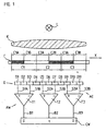
- FIG. 1 a length measuring device is shown schematically.
- This length measuring device operates on the optical scanning principle, in which a code C is scanned in the transmitted light process.
- a scanning device AE which is arranged relative to the code C movable in the measuring direction X.
- the code C consists of a succession of code elements C1, C2, C3 of the same length in the measuring direction X.
- Each code element C1, C2, C3 in turn consists of two equally long in the measuring direction X next to each other immediately successively arranged portions A and B, which are complementary to each other.
- Complementary means that they have inverse properties, ie transparent and non-transparent in the optical scanning principle or reflective or non-reflective in reflected-light scanning. Such a code is also called Manchester code.
- the sequential code C is scanned by the scanning device AE, which contains a light source L whose light illuminates a plurality of successive code elements C1, C2, C3 via a collimator lens K.
- the light is modulated position-dependent by the code C, so that behind the code C, a position-dependent light distribution is produced, which is detected by a detector unit D of the scanning AE.
- the detector unit D is a line sensor with a sequence of detector elements D1 to D11 arranged in the measuring direction X.
- Each subarea A, B of the code elements C1, C2, C3 is uniquely assigned at least one detector element D1 to D11 in each relative position, so that in each relative position of the detector unit D with respect to the code C a scanning signal S1A to S3B is obtained from each subarea A, B.
- These scanning signals S1A to S3B are fed to an evaluation device AW, which outputs the two scanning signals S1A, S1B; S2A, S2B; S3A, S3B of the two sections C1A, C1B; C2A, C2B; C3A, C3B of a code element C1, C2, C3 respectively compared with each other and generated by this comparison for each code element C1, C2, C3, a digital value or a bit B1, B2, B3.
- the digital value B1 depends on the sequence of the sections C1A and C1B.
- a sequence of several digital values B1, B2, B3 results in a codeword CW which defines the absolute position.
- FIG. 1 shows a momentary position of the code C relative to the scanner AE.
- the detector elements D1 to D11 are arranged successively at a pitch of half the width of a portion C1A to C3B of the code C. This ensures that in each position at least one detector element D1 to D11 is uniquely assigned to a subarea C1A to C3B and does not scan a transition between two subareas C1A to C3B.
- the partial area C1A is scanned by the detector element D1 and the partial area C1 B by the detector element D3.
- the detector elements D1, D3 detect the light distribution and generate an analog scanning signal S1A, S1B proportional to the light intensity as a function of the light intensity. Since the two partial regions C1A and C1B are formed complementary to one another, the intensity of the scanning signals S1A and S1B is also inversely to one another, so that the signal levels are widely spaced from one another.
- This signal distance is now utilized for generating the binary information B1 by checking which of the two scanning signals S1A, S1B of the code element C1 is larger. This test can be done by quotient or subtraction. The difference is used as an example, for which purpose FIG. 1 as a comparison device, a trigger module T1 is used.
- binary information B2 and B3 are obtained by sampling the code elements C2, C3 and comparing the analog scanning signals S2A, S2B; S3A, S3B of the sections C2A, C2B; C3A, C3B each of a code element C2, C3 obtained by trigger modules T2, T3.
- a first sequence of subareas A, B formed complementary to one another is thus assigned a first digital value and a second sequence of subareas A, B formed complementary to one another is assigned a second digital value.
- the sequence opaque ⁇ transparent is assigned the value 0 and the sequence transparent ⁇ opaque the value 1.
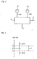
- the principle of generating the error signal F is in FIG. 2 illustrated by the code element C1.
- the analog scanning signals S1A and S1B of the code element C1 are supplied to an error checking device P.
- the error checking device P compares S1A and S1B by subtraction (S1A - S1B) and checks whether the difference amount exceeds or does not exceed a predetermined comparison value V. When the difference amount (S1A-S1B) does not exceed the predetermined comparison value V, an error signal F is output. In FIG. 3 these signal ratios are shown. This error check is performed for the strobe signals to generate all the bits B1, B2, B3 of a codeword CW.
- the reliability of the generated bits B1, B2, B3 is checked. If predetermined criteria are not met - for example, the signal amplitudes of two analog scanning signals S used to form a bit B1, B2, B3 - an error identifier F is assigned to this bit, which is recognized as being unreliable.
- the arrangement of the two subareas A and B of each code element C1, C2, C3 successively directly next to each other in the measuring direction X has the advantage that the detector elements D1 to D11 can be arranged side by side in a small distance in the measuring direction X and thus the position measuring device against rotation of the detector unit D compared to the code C, that is insensitive to moire fluctuations. Furthermore, the susceptibility to soiling is low since it can be assumed that both subareas A and B of a code element C1, C2, C3 are equally affected.
- the error check can also be carried out on the basis of digital scanning signals of two subregions A, B in each case.
- An error signal is output when it is detected that the digital samples of the partial areas A, B of a code element are not inverse (0 ⁇ 1 and 1 ⁇ 0, respectively) to each other.
- bit sequences are specified by the provision of a memory with an allocation table in the form of a ROM.
- the allocation of bit sequence to position is stored in the memory.
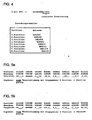
- the codeword CW forms the address for the assignment table, so that the position assigned to this address is present at the output (cf. FIG. 4 ).
- This decoding is required to standardize the codewords CW.
- bit sequence is the generation according to a predetermined educational rule, wherein the generating step uniquely determines the absolute position.
- the number of bit sequences is computationally or by means of logical elements (usually exclusiv - or - gate) formed.
- Educational regulations and circuits are, for example, in the reference: Digital displacement transducer using pseudo-random binary sequences and a microprocessor, by BE Jones and K. Zia in Trans Inst MC Vol 3, No 1, Jan-Mar 1981, pages 13 to 20 discloses, to which reference is expressly made.
- further code elements that is to say a further pattern, in particular at least part of a further code pattern, are then scanned.
- additional bits are formed.
- the bits of the code pattern as well as the additional bits are checked for reliability by, for example, performing the above-described checking of the amplitudes of the analog scanning signals S.
- the additional bits are compared with the corresponding bits of the given series of bit sequences. In this comparison, the bits marked as unreliable are disregarded.
- the comparison code word CW is assigned the absolute position stored for the found bit sequence. This position is unique. If several matches are found in the comparison, then too many bits are unreliable and further error routines are required or an error message is output because there is no clear error at this position absolute position can be determined.
- Another error routine is, for example, that it is assumed that the change between the current position and the last position can only be a predetermined value. If several matches are found in the comparison, the position is validated by the several positions whose distance from the last position does not exceed the predetermined amount or which is closest to the last determined position.
- the comparison is already limited to a neighboring area of the last determined position.
- FIG. 4 the codewords sampled at each of the 8 different positions are shown. These codewords are each formed by the first three bits. In this example, the next code word is scanned as redundant information. These additional bits are shown in italics.
- the maximum length sequence is advantageously used for angle measurement, while the maximum length sequence is used closed.
- FIG. 5a It is shown that there is no erroneous bit in the scan so that in a single comparison of the 8 compare positions, all bits match. This position can therefore be determined unambiguously and is assessed as valid.
- the redundantly sampled and used for comparison bits are advantageously to the codeword CW immediately adjacent bits, but this is not a requirement. It is only important that the redundantly sampled bits are correctly compared with bits from the given row.
- the invention is particularly advantageously applicable to a sequential one-step Manchester code.
- the invention is not limited to this code, it can also be used in multi-track coding.
- the invention can be used particularly advantageously with the optical scanning principle.
- the invention is not limited to this scanning principle, but also be used in magnetic, inductive and capacitive sensing principles.
- the position measuring device can be used for measuring linear or rotary movements.
- the objects to be measured can be the table and the carriage of a machine tool, a coordinate measuring machine or the rotor and the stator of an electric motor.
Landscapes
- Physics & Mathematics (AREA)
- General Physics & Mathematics (AREA)
- Engineering & Computer Science (AREA)
- Signal Processing (AREA)
- Transmission And Conversion Of Sensor Element Output (AREA)
- Optical Transform (AREA)
- Position Fixing By Use Of Radio Waves (AREA)
Applications Claiming Priority (2)
| Application Number | Priority Date | Filing Date | Title |
|---|---|---|---|
| DE10244547A DE10244547B4 (de) | 2002-09-25 | 2002-09-25 | Verfahren und Positionsmesseinrichtung zur Bestimmung einer absoluten Position |
| DE10244547 | 2002-09-25 |
Publications (3)
| Publication Number | Publication Date |
|---|---|
| EP1403623A1 EP1403623A1 (de) | 2004-03-31 |
| EP1403623B1 EP1403623B1 (de) | 2010-12-29 |
| EP1403623B2 true EP1403623B2 (de) | 2013-06-05 |
Family
ID=31969546
Family Applications (1)
| Application Number | Title | Priority Date | Filing Date |
|---|---|---|---|
| EP03017161.5A Expired - Lifetime EP1403623B2 (de) | 2002-09-25 | 2003-07-29 | Verfahren zur Bestimmung einer absoluten Position |
Country Status (7)
Families Citing this family (22)
| Publication number | Priority date | Publication date | Assignee | Title |
|---|---|---|---|---|
| JP4290405B2 (ja) * | 2002-10-25 | 2009-07-08 | オークマ株式会社 | 位置情報の異常検出装置 |
| TWI282047B (en) * | 2003-07-23 | 2007-06-01 | Murata Machinery Ltd | Carrying vehicle system and carrying vehicle |
| TWI290272B (en) * | 2004-03-12 | 2007-11-21 | Murata Machinery Ltd | Moving body system |
| GB0419882D0 (en) * | 2004-09-08 | 2004-10-13 | Bamford Excavators Ltd | Calculation module |
| JP5021244B2 (ja) | 2006-07-03 | 2012-09-05 | 株式会社ミツトヨ | 変位検出エンコーダ |
| JP4217918B2 (ja) * | 2006-11-28 | 2009-02-04 | 村田機械株式会社 | 移動体システム |
| JP2008140144A (ja) * | 2006-12-01 | 2008-06-19 | Murata Mach Ltd | 走行台車とそのシステム |
| DE102007018748A1 (de) * | 2007-04-20 | 2008-10-23 | Dr. Johannes Heidenhain Gmbh | Positionsmesseinrichtung |
| FR2921480B1 (fr) * | 2007-09-20 | 2010-03-05 | Renault Sas | Capteur de position absolue a lecture serie |
| DE102007045362A1 (de) * | 2007-09-22 | 2009-04-02 | Dr. Johannes Heidenhain Gmbh | Positionsmesseinrichtung |
| DE102008000630A1 (de) * | 2008-03-12 | 2009-09-17 | Robert Bosch Gmbh | Verfahren und Vorrichtung zur Überwachung und Überprüfung einer Messeinrichtung |
| EP2674731B1 (de) * | 2012-06-13 | 2015-09-02 | Dr. Johannes Heidenhain GmbH | Positionsmesseinrichtung |
| DE102013224247A1 (de) * | 2013-11-27 | 2015-05-28 | Dr. Johannes Heidenhain Gmbh | Multiturn-Drehgeber |
| JP6320149B2 (ja) * | 2014-04-21 | 2018-05-09 | キヤノン株式会社 | アブソリュートエンコーダ |
| DE102014010759B4 (de) | 2014-07-17 | 2020-06-04 | Nils Remmers | Verfahren zur Bestimmung einer Position |
| JP6634249B2 (ja) * | 2015-09-14 | 2020-01-22 | 株式会社ミツトヨ | 絶対位置検出型光電式エンコーダ |
| DE102015121432A1 (de) * | 2015-12-09 | 2017-06-14 | Sick Ag | Vorrichtung zur kontaktlosen Übertragung von Daten und zur Ermittlung einer Winkeländerung zwischen zwei sich relativ zueinander bewegenden Gegenständen |
| JP6744066B2 (ja) * | 2016-03-25 | 2020-08-19 | 株式会社ミツトヨ | 光電式エンコーダ |
| EP3270114B1 (de) * | 2016-07-15 | 2021-04-14 | Leuze electronic GmbH + Co KG | Sensoranordnung |
| JP7114371B2 (ja) * | 2018-07-03 | 2022-08-08 | 株式会社ミツトヨ | 光電式エンコーダの信号処理方法 |
| CN109341545A (zh) * | 2018-11-16 | 2019-02-15 | 广州市精谷智能科技有限公司 | 一种绝对位置位移传感器光栅绝对位置编码及译码方法 |
| CN111426339B (zh) * | 2020-06-10 | 2020-09-25 | 北京云迹科技有限公司 | 一种编码检测方法及装置 |
Citations (4)
| Publication number | Priority date | Publication date | Assignee | Title |
|---|---|---|---|---|
| GB2126444A (en) † | 1982-09-01 | 1984-03-21 | Rosemount Eng Co Ltd | Position measuring apparatus |
| US4881059A (en) † | 1987-04-30 | 1989-11-14 | American Telephone And Telegraph Company | Manchester code receiver |
| US6038523A (en) † | 1996-05-24 | 2000-03-14 | Seiko Epson Corporation | Position detector, encoder board, position detecting method, timer and electronic device |
| WO2002001160A1 (en) † | 2000-06-23 | 2002-01-03 | Bishop Innovation Limited | Position encoder using statistically biased pseudorandom sequence |
Family Cites Families (11)
| Publication number | Priority date | Publication date | Assignee | Title |
|---|---|---|---|---|
| DE3377669D1 (en) * | 1982-09-01 | 1988-09-15 | Rosemount Ltd | Position measuring apparatus |
| DE3910873A1 (de) * | 1989-04-04 | 1990-10-18 | Stahl R Foerdertech Gmbh | Positionsmessvorrichtung fuer kran- und elektrohaengebahnen |
| DE19506019C2 (de) * | 1995-02-22 | 2000-04-13 | Telefunken Microelectron | Verfahren zum Betrieb eines optischen Lenkwinkelsensors |
| DE19604871A1 (de) * | 1996-02-10 | 1997-08-14 | Heidenhain Gmbh Dr Johannes | Positionsmeßeinrichtung |
| US6483104B1 (en) * | 1996-09-23 | 2002-11-19 | Valeo Schalter Und Sensoren Gmbh | Rotational angle sensor using a CCD line with enhanced measuring precision |
| JPH10274503A (ja) * | 1997-03-25 | 1998-10-13 | Samsung Heavy Ind Co Ltd | ストロークセンシングシリンダの絶対位置検出方法 |
| SE516522C2 (sv) * | 1999-05-28 | 2002-01-22 | Anoto Ab | Positionsbestämning |
| DE19936582A1 (de) * | 1999-08-03 | 2001-02-08 | Heidenhain Gmbh Dr Johannes | Code mit möglichst unterschiedlichen aufeinanderfolgenden Codeelementen |
| DE10244235A1 (de) * | 2002-09-23 | 2004-03-25 | Dr. Johannes Heidenhain Gmbh | Positionsmesseinrichtung |
| DE50203793D1 (de) * | 2002-01-17 | 2005-09-01 | Heidenhain Gmbh Dr Johannes | Positionsmesseinrichtung |
| DE10244234A1 (de) * | 2002-09-23 | 2004-03-25 | Dr. Johannes Heidenhain Gmbh | Positionsmesseinrichtung |
-
2002
- 2002-09-25 DE DE10244547A patent/DE10244547B4/de not_active Withdrawn - After Issue
-
2003
- 2003-07-29 ES ES03017161T patent/ES2356732T5/es not_active Expired - Lifetime
- 2003-07-29 AT AT03017161T patent/ATE493636T1/de active
- 2003-07-29 DE DE50313364T patent/DE50313364D1/de not_active Expired - Lifetime
- 2003-07-29 EP EP03017161.5A patent/EP1403623B2/de not_active Expired - Lifetime
- 2003-09-24 JP JP2003331749A patent/JP4447875B2/ja not_active Expired - Lifetime
- 2003-09-25 US US10/671,325 patent/US6987465B2/en not_active Expired - Lifetime
- 2003-09-25 CN CNB031598110A patent/CN100346137C/zh not_active Expired - Fee Related
Patent Citations (4)
| Publication number | Priority date | Publication date | Assignee | Title |
|---|---|---|---|---|
| GB2126444A (en) † | 1982-09-01 | 1984-03-21 | Rosemount Eng Co Ltd | Position measuring apparatus |
| US4881059A (en) † | 1987-04-30 | 1989-11-14 | American Telephone And Telegraph Company | Manchester code receiver |
| US6038523A (en) † | 1996-05-24 | 2000-03-14 | Seiko Epson Corporation | Position detector, encoder board, position detecting method, timer and electronic device |
| WO2002001160A1 (en) † | 2000-06-23 | 2002-01-03 | Bishop Innovation Limited | Position encoder using statistically biased pseudorandom sequence |
Non-Patent Citations (3)
| Title |
|---|
| "Electronics Letters", vol. 29, part 10 13 May 1993, article M.ARSICI, D.DENICI: "New Pseudorandom Code Reading Method Applied to Position Encoders", pages: 893 - 894 † |
| "IEEE Instrumentation& Measurement Magazine", vol. 1/3, September 1998, article E.M. PETRIU: "Absolute position measurement using pseudo-random binary encoding", pages: 19 - 23 † |
| "IEEE Trans.", 1989, article PETRIU E., BASRAN, J.: "On the position measurement of automated guided vehicles using pseudorandom encoding", pages: 799 - 803 † |
Also Published As
| Publication number | Publication date |
|---|---|
| ES2356732T5 (es) | 2013-08-30 |
| DE10244547A1 (de) | 2004-04-08 |
| CN100346137C (zh) | 2007-10-31 |
| EP1403623A1 (de) | 2004-03-31 |
| US20040133844A1 (en) | 2004-07-08 |
| JP2004117360A (ja) | 2004-04-15 |
| CN1497243A (zh) | 2004-05-19 |
| EP1403623B1 (de) | 2010-12-29 |
| DE50313364D1 (de) | 2011-02-10 |
| ES2356732T3 (es) | 2011-04-12 |
| ATE493636T1 (de) | 2011-01-15 |
| DE10244547B4 (de) | 2010-11-11 |
| JP4447875B2 (ja) | 2010-04-07 |
| US6987465B2 (en) | 2006-01-17 |
Similar Documents
| Publication | Publication Date | Title |
|---|---|---|
| EP1403623B2 (de) | Verfahren zur Bestimmung einer absoluten Position | |
| EP1821073B1 (de) | Positionsmesseinrichtung | |
| EP1400778B1 (de) | Positionsmesseinrichtung | |
| EP1468254B1 (de) | Positionsmesseinrichtung | |
| EP2040041B1 (de) | Positionsmesseinrichtung und Verfahren zur Positionsmessung | |
| DE3427411C2 (de) | Meßeinrichtung | |
| EP1983308B1 (de) | Positionsmesseinrichtung | |
| EP0789226B1 (de) | Positionsmesseinrichtung | |
| EP4242595B1 (de) | Vorrichtung und verfahren zur positions-, längen- oder winkelbestimmung | |
| WO2010049047A1 (de) | Absolute winkelcodierung und winkelmessvorrichtung | |
| DE102006010161A1 (de) | Codestruktur für eine Positionsmesseinrichtung und Positionsmesseinrichtung mit einer solchen Codestruktur | |
| DE10049502A1 (de) | Verfahren und Vorrichtung zur absoluten Positionsbestimmung | |
| EP2725325B1 (de) | Positionsmesssystem | |
| EP2342539B1 (de) | Absolute positionsmessvorrichtung | |
| DE10244923B4 (de) | Positionsmesseinrichtung und Verfahren zur Positionsbestimmung | |
| DE102021110583B4 (de) | Gebervorrichtung und Verfahren zur Bestimmung einer Absolutposition | |
| DE202019101115U1 (de) | Vorrichtung zur Positions-, Längen- oder Winkelbestimmung | |
| DE102007025071A1 (de) | Absolutlageerfassungseinrichtung | |
| DE10244235A1 (de) | Positionsmesseinrichtung | |
| EP2340418B1 (de) | Absolute positionscodierung und positionsmessvorrichtung | |
| EP4571267A1 (de) | Vorrichtung und verfahren zur positions-, längen- oder winkelbestimmung | |
| DE4324381A1 (de) | Optischer Positionsgeber |
Legal Events
| Date | Code | Title | Description |
|---|---|---|---|
| PUAI | Public reference made under article 153(3) epc to a published international application that has entered the european phase |
Free format text: ORIGINAL CODE: 0009012 |
|
| AK | Designated contracting states |
Kind code of ref document: A1 Designated state(s): AT BE BG CH CY CZ DE DK EE ES FI FR GB GR HU IE IT LI LU MC NL PT RO SE SI SK TR |
|
| AX | Request for extension of the european patent |
Extension state: AL LT LV MK |
|
| 17P | Request for examination filed |
Effective date: 20040930 |
|
| AKX | Designation fees paid |
Designated state(s): AT BE BG CH CY CZ DE DK EE ES FI FR GB GR HU IE IT LI LU MC NL PT RO SE SI SK TR |
|
| GRAP | Despatch of communication of intention to grant a patent |
Free format text: ORIGINAL CODE: EPIDOSNIGR1 |
|
| GRAS | Grant fee paid |
Free format text: ORIGINAL CODE: EPIDOSNIGR3 |
|
| GRAA | (expected) grant |
Free format text: ORIGINAL CODE: 0009210 |
|
| AK | Designated contracting states |
Kind code of ref document: B1 Designated state(s): AT BE BG CH CY CZ DE DK EE ES FI FR GB GR HU IE IT LI LU MC NL PT RO SE SI SK TR |
|
| REG | Reference to a national code |
Ref country code: GB Ref legal event code: FG4D Free format text: NOT ENGLISH |
|
| REG | Reference to a national code |
Ref country code: CH Ref legal event code: EP |
|
| REG | Reference to a national code |
Ref country code: CH Ref legal event code: NV Representative=s name: ICB INGENIEURS CONSEILS EN BREVETS SA |
|
| REG | Reference to a national code |
Ref country code: IE Ref legal event code: FG4D Free format text: LANGUAGE OF EP DOCUMENT: GERMAN |
|
| REF | Corresponds to: |
Ref document number: 50313364 Country of ref document: DE Date of ref document: 20110210 Kind code of ref document: P |
|
| REG | Reference to a national code |
Ref country code: DE Ref legal event code: R096 Ref document number: 50313364 Country of ref document: DE Effective date: 20110210 |
|
| REG | Reference to a national code |
Ref country code: ES Ref legal event code: FG2A Ref document number: 2356732 Country of ref document: ES Kind code of ref document: T3 Effective date: 20110412 |
|
| REG | Reference to a national code |
Ref country code: NL Ref legal event code: VDEP Effective date: 20101229 |
|
| PG25 | Lapsed in a contracting state [announced via postgrant information from national office to epo] |
Ref country code: CY Free format text: LAPSE BECAUSE OF FAILURE TO SUBMIT A TRANSLATION OF THE DESCRIPTION OR TO PAY THE FEE WITHIN THE PRESCRIBED TIME-LIMIT Effective date: 20101229 Ref country code: SE Free format text: LAPSE BECAUSE OF FAILURE TO SUBMIT A TRANSLATION OF THE DESCRIPTION OR TO PAY THE FEE WITHIN THE PRESCRIBED TIME-LIMIT Effective date: 20101229 Ref country code: BG Free format text: LAPSE BECAUSE OF FAILURE TO SUBMIT A TRANSLATION OF THE DESCRIPTION OR TO PAY THE FEE WITHIN THE PRESCRIBED TIME-LIMIT Effective date: 20110329 Ref country code: SI Free format text: LAPSE BECAUSE OF FAILURE TO SUBMIT A TRANSLATION OF THE DESCRIPTION OR TO PAY THE FEE WITHIN THE PRESCRIBED TIME-LIMIT Effective date: 20101229 Ref country code: FI Free format text: LAPSE BECAUSE OF FAILURE TO SUBMIT A TRANSLATION OF THE DESCRIPTION OR TO PAY THE FEE WITHIN THE PRESCRIBED TIME-LIMIT Effective date: 20101229 |
|
| REG | Reference to a national code |
Ref country code: IE Ref legal event code: FD4D |
|
| PG25 | Lapsed in a contracting state [announced via postgrant information from national office to epo] |
Ref country code: PT Free format text: LAPSE BECAUSE OF FAILURE TO SUBMIT A TRANSLATION OF THE DESCRIPTION OR TO PAY THE FEE WITHIN THE PRESCRIBED TIME-LIMIT Effective date: 20110429 Ref country code: CZ Free format text: LAPSE BECAUSE OF FAILURE TO SUBMIT A TRANSLATION OF THE DESCRIPTION OR TO PAY THE FEE WITHIN THE PRESCRIBED TIME-LIMIT Effective date: 20101229 Ref country code: EE Free format text: LAPSE BECAUSE OF FAILURE TO SUBMIT A TRANSLATION OF THE DESCRIPTION OR TO PAY THE FEE WITHIN THE PRESCRIBED TIME-LIMIT Effective date: 20101229 Ref country code: GR Free format text: LAPSE BECAUSE OF FAILURE TO SUBMIT A TRANSLATION OF THE DESCRIPTION OR TO PAY THE FEE WITHIN THE PRESCRIBED TIME-LIMIT Effective date: 20110330 |
|
| PG25 | Lapsed in a contracting state [announced via postgrant information from national office to epo] |
Ref country code: NL Free format text: LAPSE BECAUSE OF FAILURE TO SUBMIT A TRANSLATION OF THE DESCRIPTION OR TO PAY THE FEE WITHIN THE PRESCRIBED TIME-LIMIT Effective date: 20101229 Ref country code: RO Free format text: LAPSE BECAUSE OF FAILURE TO SUBMIT A TRANSLATION OF THE DESCRIPTION OR TO PAY THE FEE WITHIN THE PRESCRIBED TIME-LIMIT Effective date: 20101229 Ref country code: SK Free format text: LAPSE BECAUSE OF FAILURE TO SUBMIT A TRANSLATION OF THE DESCRIPTION OR TO PAY THE FEE WITHIN THE PRESCRIBED TIME-LIMIT Effective date: 20101229 |
|
| PLBI | Opposition filed |
Free format text: ORIGINAL CODE: 0009260 |
|
| 26 | Opposition filed |
Opponent name: SICK STEGMANN GMBH Effective date: 20110826 |
|
| PG25 | Lapsed in a contracting state [announced via postgrant information from national office to epo] |
Ref country code: DK Free format text: LAPSE BECAUSE OF FAILURE TO SUBMIT A TRANSLATION OF THE DESCRIPTION OR TO PAY THE FEE WITHIN THE PRESCRIBED TIME-LIMIT Effective date: 20101229 Ref country code: IE Free format text: LAPSE BECAUSE OF FAILURE TO SUBMIT A TRANSLATION OF THE DESCRIPTION OR TO PAY THE FEE WITHIN THE PRESCRIBED TIME-LIMIT Effective date: 20101229 |
|
| PLAX | Notice of opposition and request to file observation + time limit sent |
Free format text: ORIGINAL CODE: EPIDOSNOBS2 |
|
| PLBB | Reply of patent proprietor to notice(s) of opposition received |
Free format text: ORIGINAL CODE: EPIDOSNOBS3 |
|
| REG | Reference to a national code |
Ref country code: DE Ref legal event code: R026 Ref document number: 50313364 Country of ref document: DE Effective date: 20110826 |
|
| BERE | Be: lapsed |
Owner name: DR. JOHANNES HEIDENHAIN G.M.B.H. Effective date: 20110731 |
|
| PG25 | Lapsed in a contracting state [announced via postgrant information from national office to epo] |
Ref country code: MC Free format text: LAPSE BECAUSE OF NON-PAYMENT OF DUE FEES Effective date: 20110731 |
|
| REG | Reference to a national code |
Ref country code: FR Ref legal event code: ST Effective date: 20120330 |
|
| PG25 | Lapsed in a contracting state [announced via postgrant information from national office to epo] |
Ref country code: FR Free format text: LAPSE BECAUSE OF NON-PAYMENT OF DUE FEES Effective date: 20110801 Ref country code: BE Free format text: LAPSE BECAUSE OF NON-PAYMENT OF DUE FEES Effective date: 20110731 |
|
| PG25 | Lapsed in a contracting state [announced via postgrant information from national office to epo] |
Ref country code: IT Free format text: LAPSE BECAUSE OF FAILURE TO SUBMIT A TRANSLATION OF THE DESCRIPTION OR TO PAY THE FEE WITHIN THE PRESCRIBED TIME-LIMIT Effective date: 20101229 |
|
| RIC2 | Information provided on ipc code assigned after grant |
Ipc: G01D 5/249 20060101AFI20121106BHEP Ipc: G01D 5/347 20060101ALI20121106BHEP Ipc: G01D 5/244 20060101ALI20121106BHEP |
|
| REG | Reference to a national code |
Ref country code: AT Ref legal event code: MM01 Ref document number: 493636 Country of ref document: AT Kind code of ref document: T Effective date: 20110729 |
|
| PG25 | Lapsed in a contracting state [announced via postgrant information from national office to epo] |
Ref country code: AT Free format text: LAPSE BECAUSE OF NON-PAYMENT OF DUE FEES Effective date: 20110729 |
|
| PUAH | Patent maintained in amended form |
Free format text: ORIGINAL CODE: 0009272 |
|
| STAA | Information on the status of an ep patent application or granted ep patent |
Free format text: STATUS: PATENT MAINTAINED AS AMENDED |
|
| PG25 | Lapsed in a contracting state [announced via postgrant information from national office to epo] |
Ref country code: LU Free format text: LAPSE BECAUSE OF NON-PAYMENT OF DUE FEES Effective date: 20110729 |
|
| 27A | Patent maintained in amended form |
Effective date: 20130605 |
|
| AK | Designated contracting states |
Kind code of ref document: B2 Designated state(s): AT BE BG CH CY CZ DE DK EE ES FI FR GB GR HU IE IT LI LU MC NL PT RO SE SI SK TR |
|
| REG | Reference to a national code |
Ref country code: CH Ref legal event code: AELC |
|
| REG | Reference to a national code |
Ref country code: DE Ref legal event code: R102 Ref document number: 50313364 Country of ref document: DE Effective date: 20130605 |
|
| PG25 | Lapsed in a contracting state [announced via postgrant information from national office to epo] |
Ref country code: TR Free format text: LAPSE BECAUSE OF FAILURE TO SUBMIT A TRANSLATION OF THE DESCRIPTION OR TO PAY THE FEE WITHIN THE PRESCRIBED TIME-LIMIT Effective date: 20101229 |
|
| PG25 | Lapsed in a contracting state [announced via postgrant information from national office to epo] |
Ref country code: HU Free format text: LAPSE BECAUSE OF FAILURE TO SUBMIT A TRANSLATION OF THE DESCRIPTION OR TO PAY THE FEE WITHIN THE PRESCRIBED TIME-LIMIT Effective date: 20101229 |
|
| PGFP | Annual fee paid to national office [announced via postgrant information from national office to epo] |
Ref country code: ES Payment date: 20210927 Year of fee payment: 19 Ref country code: GB Payment date: 20210721 Year of fee payment: 19 Ref country code: DE Payment date: 20210721 Year of fee payment: 19 Ref country code: CH Payment date: 20210721 Year of fee payment: 19 |
|
| REG | Reference to a national code |
Ref country code: DE Ref legal event code: R119 Ref document number: 50313364 Country of ref document: DE |
|
| REG | Reference to a national code |
Ref country code: CH Ref legal event code: PL |
|
| GBPC | Gb: european patent ceased through non-payment of renewal fee |
Effective date: 20220729 |
|
| PG25 | Lapsed in a contracting state [announced via postgrant information from national office to epo] |
Ref country code: LI Free format text: LAPSE BECAUSE OF NON-PAYMENT OF DUE FEES Effective date: 20220731 Ref country code: CH Free format text: LAPSE BECAUSE OF NON-PAYMENT OF DUE FEES Effective date: 20220731 |
|
| PG25 | Lapsed in a contracting state [announced via postgrant information from national office to epo] |
Ref country code: GB Free format text: LAPSE BECAUSE OF NON-PAYMENT OF DUE FEES Effective date: 20220729 Ref country code: DE Free format text: LAPSE BECAUSE OF NON-PAYMENT OF DUE FEES Effective date: 20230201 |
|
| REG | Reference to a national code |
Ref country code: ES Ref legal event code: FD2A Effective date: 20230901 |
|
| PG25 | Lapsed in a contracting state [announced via postgrant information from national office to epo] |
Ref country code: ES Free format text: LAPSE BECAUSE OF NON-PAYMENT OF DUE FEES Effective date: 20220730 |