EP1403537A1 - Arbre avec denture à cannelures et une rainure de décharge des contraintes et son procédé de fabrication - Google Patents
Arbre avec denture à cannelures et une rainure de décharge des contraintes et son procédé de fabrication Download PDFInfo
- Publication number
- EP1403537A1 EP1403537A1 EP20030021958 EP03021958A EP1403537A1 EP 1403537 A1 EP1403537 A1 EP 1403537A1 EP 20030021958 EP20030021958 EP 20030021958 EP 03021958 A EP03021958 A EP 03021958A EP 1403537 A1 EP1403537 A1 EP 1403537A1
- Authority
- EP
- European Patent Office
- Prior art keywords
- splined
- shaft
- curved
- shank
- diameter
- Prior art date
- Legal status (The legal status is an assumption and is not a legal conclusion. Google has not performed a legal analysis and makes no representation as to the accuracy of the status listed.)
- Granted
Links
- 238000004519 manufacturing process Methods 0.000 title claims description 20
- 230000002093 peripheral effect Effects 0.000 claims abstract description 8
- 238000005096 rolling process Methods 0.000 claims description 11
- 238000010791 quenching Methods 0.000 claims description 8
- 230000000171 quenching effect Effects 0.000 claims description 8
- 238000003754 machining Methods 0.000 claims description 7
- 238000005480 shot peening Methods 0.000 claims description 7
- 238000010273 cold forging Methods 0.000 claims description 4
- 238000000926 separation method Methods 0.000 claims 1
- 230000000694 effects Effects 0.000 description 14
- 238000009792 diffusion process Methods 0.000 description 2
- 239000011324 bead Substances 0.000 description 1
- 230000005540 biological transmission Effects 0.000 description 1
- 238000005520 cutting process Methods 0.000 description 1
- 230000001771 impaired effect Effects 0.000 description 1
- 238000010348 incorporation Methods 0.000 description 1
- 238000005259 measurement Methods 0.000 description 1
- 238000000034 method Methods 0.000 description 1
- 238000012986 modification Methods 0.000 description 1
- 230000004048 modification Effects 0.000 description 1
- 238000012795 verification Methods 0.000 description 1
Images


Classifications
-
- F—MECHANICAL ENGINEERING; LIGHTING; HEATING; WEAPONS; BLASTING
- F16—ENGINEERING ELEMENTS AND UNITS; GENERAL MEASURES FOR PRODUCING AND MAINTAINING EFFECTIVE FUNCTIONING OF MACHINES OR INSTALLATIONS; THERMAL INSULATION IN GENERAL
- F16D—COUPLINGS FOR TRANSMITTING ROTATION; CLUTCHES; BRAKES
- F16D1/00—Couplings for rigidly connecting two coaxial shafts or other movable machine elements
- F16D1/06—Couplings for rigidly connecting two coaxial shafts or other movable machine elements for attachment of a member on a shaft or on a shaft-end
-
- F—MECHANICAL ENGINEERING; LIGHTING; HEATING; WEAPONS; BLASTING
- F16—ENGINEERING ELEMENTS AND UNITS; GENERAL MEASURES FOR PRODUCING AND MAINTAINING EFFECTIVE FUNCTIONING OF MACHINES OR INSTALLATIONS; THERMAL INSULATION IN GENERAL
- F16C—SHAFTS; FLEXIBLE SHAFTS; ELEMENTS OR CRANKSHAFT MECHANISMS; ROTARY BODIES OTHER THAN GEARING ELEMENTS; BEARINGS
- F16C3/00—Shafts; Axles; Cranks; Eccentrics
- F16C3/02—Shafts; Axles
-
- F—MECHANICAL ENGINEERING; LIGHTING; HEATING; WEAPONS; BLASTING
- F16—ENGINEERING ELEMENTS AND UNITS; GENERAL MEASURES FOR PRODUCING AND MAINTAINING EFFECTIVE FUNCTIONING OF MACHINES OR INSTALLATIONS; THERMAL INSULATION IN GENERAL
- F16D—COUPLINGS FOR TRANSMITTING ROTATION; CLUTCHES; BRAKES
- F16D1/00—Couplings for rigidly connecting two coaxial shafts or other movable machine elements
- F16D1/06—Couplings for rigidly connecting two coaxial shafts or other movable machine elements for attachment of a member on a shaft or on a shaft-end
- F16D1/064—Couplings for rigidly connecting two coaxial shafts or other movable machine elements for attachment of a member on a shaft or on a shaft-end non-disconnectable
- F16D1/072—Couplings for rigidly connecting two coaxial shafts or other movable machine elements for attachment of a member on a shaft or on a shaft-end non-disconnectable involving plastic deformation
-
- F—MECHANICAL ENGINEERING; LIGHTING; HEATING; WEAPONS; BLASTING
- F16—ENGINEERING ELEMENTS AND UNITS; GENERAL MEASURES FOR PRODUCING AND MAINTAINING EFFECTIVE FUNCTIONING OF MACHINES OR INSTALLATIONS; THERMAL INSULATION IN GENERAL
- F16D—COUPLINGS FOR TRANSMITTING ROTATION; CLUTCHES; BRAKES
- F16D1/00—Couplings for rigidly connecting two coaxial shafts or other movable machine elements
- F16D1/06—Couplings for rigidly connecting two coaxial shafts or other movable machine elements for attachment of a member on a shaft or on a shaft-end
- F16D1/08—Couplings for rigidly connecting two coaxial shafts or other movable machine elements for attachment of a member on a shaft or on a shaft-end with clamping hub; with hub and longitudinal key
- F16D1/0852—Couplings for rigidly connecting two coaxial shafts or other movable machine elements for attachment of a member on a shaft or on a shaft-end with clamping hub; with hub and longitudinal key with radial clamping between the mating surfaces of the hub and shaft
- F16D1/0858—Couplings for rigidly connecting two coaxial shafts or other movable machine elements for attachment of a member on a shaft or on a shaft-end with clamping hub; with hub and longitudinal key with radial clamping between the mating surfaces of the hub and shaft due to the elasticity of the hub (including shrink fits)
-
- F—MECHANICAL ENGINEERING; LIGHTING; HEATING; WEAPONS; BLASTING
- F16—ENGINEERING ELEMENTS AND UNITS; GENERAL MEASURES FOR PRODUCING AND MAINTAINING EFFECTIVE FUNCTIONING OF MACHINES OR INSTALLATIONS; THERMAL INSULATION IN GENERAL
- F16D—COUPLINGS FOR TRANSMITTING ROTATION; CLUTCHES; BRAKES
- F16D1/00—Couplings for rigidly connecting two coaxial shafts or other movable machine elements
- F16D1/10—Quick-acting couplings in which the parts are connected by simply bringing them together axially
-
- F—MECHANICAL ENGINEERING; LIGHTING; HEATING; WEAPONS; BLASTING
- F16—ENGINEERING ELEMENTS AND UNITS; GENERAL MEASURES FOR PRODUCING AND MAINTAINING EFFECTIVE FUNCTIONING OF MACHINES OR INSTALLATIONS; THERMAL INSULATION IN GENERAL
- F16D—COUPLINGS FOR TRANSMITTING ROTATION; CLUTCHES; BRAKES
- F16D3/00—Yielding couplings, i.e. with means permitting movement between the connected parts during the drive
- F16D3/16—Universal joints in which flexibility is produced by means of pivots or sliding or rolling connecting parts
- F16D3/20—Universal joints in which flexibility is produced by means of pivots or sliding or rolling connecting parts one coupling part entering a sleeve of the other coupling part and connected thereto by sliding or rolling members
- F16D3/202—Universal joints in which flexibility is produced by means of pivots or sliding or rolling connecting parts one coupling part entering a sleeve of the other coupling part and connected thereto by sliding or rolling members one coupling part having radially projecting pins, e.g. tripod joints
- F16D3/205—Universal joints in which flexibility is produced by means of pivots or sliding or rolling connecting parts one coupling part entering a sleeve of the other coupling part and connected thereto by sliding or rolling members one coupling part having radially projecting pins, e.g. tripod joints the pins extending radially outwardly from the coupling part
- F16D3/2055—Universal joints in which flexibility is produced by means of pivots or sliding or rolling connecting parts one coupling part entering a sleeve of the other coupling part and connected thereto by sliding or rolling members one coupling part having radially projecting pins, e.g. tripod joints the pins extending radially outwardly from the coupling part having three pins, i.e. true tripod joints
-
- F—MECHANICAL ENGINEERING; LIGHTING; HEATING; WEAPONS; BLASTING
- F16—ENGINEERING ELEMENTS AND UNITS; GENERAL MEASURES FOR PRODUCING AND MAINTAINING EFFECTIVE FUNCTIONING OF MACHINES OR INSTALLATIONS; THERMAL INSULATION IN GENERAL
- F16C—SHAFTS; FLEXIBLE SHAFTS; ELEMENTS OR CRANKSHAFT MECHANISMS; ROTARY BODIES OTHER THAN GEARING ELEMENTS; BEARINGS
- F16C2240/00—Specified values or numerical ranges of parameters; Relations between them
- F16C2240/40—Linear dimensions, e.g. length, radius, thickness, gap
- F16C2240/70—Diameters; Radii
-
- F—MECHANICAL ENGINEERING; LIGHTING; HEATING; WEAPONS; BLASTING
- F16—ENGINEERING ELEMENTS AND UNITS; GENERAL MEASURES FOR PRODUCING AND MAINTAINING EFFECTIVE FUNCTIONING OF MACHINES OR INSTALLATIONS; THERMAL INSULATION IN GENERAL
- F16C—SHAFTS; FLEXIBLE SHAFTS; ELEMENTS OR CRANKSHAFT MECHANISMS; ROTARY BODIES OTHER THAN GEARING ELEMENTS; BEARINGS
- F16C2361/00—Apparatus or articles in engineering in general
- F16C2361/41—Couplings
-
- F—MECHANICAL ENGINEERING; LIGHTING; HEATING; WEAPONS; BLASTING
- F16—ENGINEERING ELEMENTS AND UNITS; GENERAL MEASURES FOR PRODUCING AND MAINTAINING EFFECTIVE FUNCTIONING OF MACHINES OR INSTALLATIONS; THERMAL INSULATION IN GENERAL
- F16D—COUPLINGS FOR TRANSMITTING ROTATION; CLUTCHES; BRAKES
- F16D1/00—Couplings for rigidly connecting two coaxial shafts or other movable machine elements
- F16D1/10—Quick-acting couplings in which the parts are connected by simply bringing them together axially
- F16D2001/103—Quick-acting couplings in which the parts are connected by simply bringing them together axially the torque is transmitted via splined connections
-
- Y—GENERAL TAGGING OF NEW TECHNOLOGICAL DEVELOPMENTS; GENERAL TAGGING OF CROSS-SECTIONAL TECHNOLOGIES SPANNING OVER SEVERAL SECTIONS OF THE IPC; TECHNICAL SUBJECTS COVERED BY FORMER USPC CROSS-REFERENCE ART COLLECTIONS [XRACs] AND DIGESTS
- Y10—TECHNICAL SUBJECTS COVERED BY FORMER USPC
- Y10T—TECHNICAL SUBJECTS COVERED BY FORMER US CLASSIFICATION
- Y10T403/00—Joints and connections
- Y10T403/70—Interfitted members
- Y10T403/7026—Longitudinally splined or fluted rod
- Y10T403/7035—Specific angle or shape of rib, key, groove, or shoulder
Definitions
- the present invention relates to a shaft that is installed in an automobile and in various types of industrial machine and a manufacturing method thereof.
- a shaft used in a constant velocity joint, or the like has a shank having a splined portion provided at an outer peripheral surface. Furthermore, a large diameter portion having a diameter larger than a diameter of the outer periphery of the splined portion is provided at an end portion of the splined portion in the direction that a fitting member such as an inner race is inserted onto the splined portion. When the fitting member is fitted, the large diameter portion acts as a stopper for stopping the fitting member.
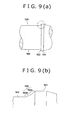
- a shank 100 having a main portion 105 with a constant radius with respect to a shaft axis; a slanted portion 102; and a large diameter portion 101 is prepared.
- the slanted portion 102 as shown in FIG. 9 (b), is formed from a tapered portion 102a and a curved portion 102b that extend continuously from a portion adjacent to the large diameter portion 101.
- a small diameter portion 103 and a splined portion 104 are formed in the main portion 105 in this order, from the larger diameter 101 portion side thereof.
- the small diameter portion 103 is provided so as to inhibit interference between the large diameter portion 101 and cutting tool when the splined portion 104 is being machined.
- the diameter of the small diameter portion 103 is constant along its entire length. Further, normally, the diameter of the small diameter portion 103 is larger than a diameter of a groove portion 104a of the splined portion 104, and smaller than a diameter of the main portion 105 prior to machining of the splined portion 104.
- a cut back portion 104b is formed at a portion that runs from the groove portion 104a of the splined portion 104 to the small diameter portion 103.
- This cut back portion 104b is formed from a tapered portion 104b2 and a curved portion 104b1 that extend successively from the small diameter portion 103 side.
- a fitting member 200 which acts as an inward joint member of the constant velocity joint, having a splined portion 204 that faces the large diameter portion 101 is fitted onto the shank 100 configured as described above. At this time, the fitting member 200 abuts with the slanted portion 102. When this occurs, load is applied from the fitting member 200 to the slanted portion 102 (in the direction shown by the arrow in FIG. 10(b)). Moreover, in the constant velocity joint, load applied to a tooth flank of the splined portion 104 is applied to the cut back portion 104b and stress concentration occurs between the cut back portion 104b and the small diameter portion 103.
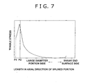
- FIG. 7 shows tensile stress exerted in the direction along with the shaft axis of the shank 100 when the fitting member 200 is fitted.
- a starting position on the side of the large diameter portion 101 of the splined portion 104 of the shank 100 is taken as P1
- a fitting starting position of the splined portion 104 for fitting with the fitting member 200 is taken as P2.
- Patent Document 1 a structure has been proposed (refer to Patent Document 1) for reducing this stress concentration of the small diameter portion 103 between the cut back portion 104b and the large diameter portion 101.
- This structure is configured such that a smooth portion with a diameter smaller than the groove portion 104a of the splined portion 104 is provided at the small diameter portion 103.
- Patent Document 1 Japanese Patent Publication Laid-Open No. Hei. 09-042303 paragraph [0015] and [0016], and FIG. 2.
- a shaft includes a shank with a splined portion that is spline engaged with a fitting member, and an external diameter portion that is formed separately from the splined portion, both the splined portion and the external diameter portion being formed in an outer peripheral surface of the shank.
- This shaft is provided with any one of a curved portion; a plurality of curved portions; and a plurality of curved portions and at least one straight portion, that extend continuously so as to connect a cut back portion formed at an end portion of a groove portion of the splined portion and the external diameter portion.
- splined portion indicates a portion provided with a plurality of slots that are formed parallel to a shaft axis of the shank, or a portion that has serrations with an inverted triangular chevron cross-sectional shape.
- a shaft according to the first aspect of the present invention may be formed with a large diameter portion which has a diameter that is larger than a diameter of an external periphery of the splined portion at an end portion of the external diameter portion of the shaft at the splined portion side. Further, a tapered portion which stops the fitting member may be provided at a side surface of the large diameter portion at the splined portion side.
- the shaft according to the first aspect of the present invention may be provided with an end portion at the external diameter portion side of the shaft of the curved portion. This end portion is formed so as to be further from the shaft axis of the shank than the cut back portion.
- the shaft according to the first aspect of the present invention may be provided with two of the curved portions.
- the shaft according to the first aspect of the present invention may be provided with two of the straight portions.
- the first aspect and its various configurations allow the strength of the shank itself to be maintained while reducing stress concentration that occurs locally.
- a manufacturing method for manufacturing the shaft according to the first aspect or any of its configurations includes the steps of: forming the splined portion with a predetermined shape by cold forging, machining and component rolling; forming the curved portion by component rolling; and conducting quenching.
- a step of shot peening may be conducted after conducting quenching.
- the configurations of the second aspect of the present invention make it possible to easily manufacture the aforementioned shaft.
- a first embodiment which is a concrete embodiment of the present invention as a shaft for a universal joint, namely, a tripod joint, will be explained in detail with reference to FIG. 1 and FIG. 2.
- a shank 10 is provided at an end of a shaft 1.
- a splined portion 14 and a large diameter portion 11 which acts as an outer diameter portion and which is positioned separately from the splined portion 14 are formed on the shank 10.
- This large diameter portion 11 has a diameter that is larger than an outer periphery of the splined portion 14.
- a plurality of slots (hereinafter referred to as "groove portion 14a") are formed in parallel to a shaft axis of the shank 10, and a plurality of splines 14c are formed along a circumferential direction of the shank 10.
- a radius of the groove portion 14a is constant with respect to the shaft axis of the shank 10, with the exception of an end portion near to the large diameter portion 11.
- an inward joint member 2 of the tripod joint which acts as a fitting member, is press fitted to the splined portion 14.
- a tapered portion 12 that stops the inward joint member 2 is provided in a side surface of the large diameter portion 11 on the splined portion 14 side.
- This tapered portion 12 is formed such that its diameter with respect to the shaft axis of the shank 10 becomes smaller in a linear manner, as the tapered portion 12 extends from an external peripheral surface of the large diameter portion 11 toward the splined portion 14 side.
- an end portion of the tapered portion 12 at the splined portion 14 side will be referred to as a "small diameter end portion".
- the end portion of the groove portion 14a near to the large diameter portion 11 is formed as a curved portion, namely, a cut back portion 14b, that extends continuously with a second curved portion 13b. Accordingly, there is a diameter difference d1 between the diameter of a portion of the groove portion 14a of the splined portion 14, excluding the cut back portion 14b, and the diameter of the end portion of the second curved portion 13b near to the splined portion 14.
- first curved portion 13a as a curved portion
- flat portion 15 that is a straight portion that has a diameter that is constant with respect to the shaft axis
- the second curved portion 13b as a curved portion
- two curved portions and one straight portion are provided between the cut back portion 14b and the tapered portion 12.
- the end portions of the first and second curved portions 13a and 13b at the large diameter 11 side are formed so as to have respective radiuses with respect to (distance from) the shaft axis of the shank 10 that are larger than that of the cut back portion 14b.
- the shank 10 is manufactured as was explained with reference to the conventional art as shank 100.
- the splined portion 14 is formed so as to have a predetermined shape.
- the groove portion 14a including the cut back portion 14b, is formed.
- the second curved portion 13b, the flat portion 15 and the first curved portion 13a are formed by conducting component rolling. The forming of each of these portions is executed continuously in order.
- quenching is executed, and then shot peening of the portion including the second curved portion 13b, the flat portion 15, the first curved portion 13a and the tapered portion 12 is conducted.
- the first curved portion 13a, the flat portion 15, and the second curved portion 13b are provided so as to interpose between the tapered portion 12 and the cut back portion 14b.
- Load is applied to the tapered portion 12 along the direction of the shaft axis of the shank 10 (the direction indicated by the arrow shown in FIG. 2) by the inward joint member 2. Accordingly, this load is not dispersed over the surface that is parallel to the load application direction, namely, the flat portion 15. However, the load is transmitted to the first and second curved portions 13a and 13b from the tapered portion 12. As a result, stress concentration occurence in the tapered portion 12 is reduced.
- the diameter difference d1 is reduced as compared to that of the conventional shank.
- the externality of the conventional shaft which is configured by splined portion 104 and small diameter portion 103, is indicated by two-dotted chain line. Further, text H indicates the size of the small diameter portion 103 of the conventional shaft. As can be seen from FIG. 2, there is a diameter difference d0 between the diameter of the conventional groove portion of the splined portion and the diameter of the tip portion of the small diameter portion on the splined portion side.
- the size in the radial direction of the cut back portion 14b is made smaller. Accordingly, strength of a diameter periphery portion of a spline pitch circle is reduced as compared to the conventional shank, and the splines 14c become easier to bend in a circumferential direction of the shank 10.
- the configuration of the shank 10 between the cut back portion 14b of the splined portion 14 and the small diameter end portion of the tapered portion 12 is different to that of the previous embodiments.
- a first curved portion 23a and a second curved portion 23b having a radius of curvature that is larger than that of the first curved portion 23a are interposed and extend continuously in this order between the cut back portion 14b and the tapered portion 12, from the tapered portion 12 side.
- two curved portions are provided between the cut back portion 14b and the tapered portion 12.
- End portions of the first and second curved portions 23a and 23b at the large diameter portion 11 side are formed so as to have respective radiuses with respect to (distance from) the shaft axis of the shank 10 that are larger than that of the cut back portion 14b.
- FIG. 3 the externality of the conventional shaft, which is configured by splined portion 104 and small diameter portion 103, is indicated by two-dotted chain line. Further, text H indicates the size of the small diameter portion 103 of the conventional shaft. As can be seen from FIG. 3, there is a diameter difference d0 between the diameter of the conventional groove portion of the splined portion and the diameter of the tip portion of the small diameter portion on the splined portion side.
- the size in the radial direction of the cut back portion 14b is made smaller. Accordingly, strength of a diameter peripheral portion of a spline pitch circle is reduced as compared to the conventional shank, and the splines 14c become easier to bend in a circumferential direction of the shank 10.
- the shaft 1 of the second embodiment in addition to effects (2), (4) and (5) of the first embodiment, the following effects can be obtained.
- the cut back portion 14b formed at the end portion of the splined portion 14 at the large diameter portion 11 side and the tapered portion 12 are connected by the continuous extension of both (the plurality of) the first curved portion 23a and the second curved portion 23b. Accordingly, effects (1) and (3) of the first embodiment can be obtained.
- the configuration of the shank 10 between the cut back portion 14b of the splined portion 14 and the small diameter end portion of the tapered portion 12 is different to that of the previous embodiments.
- a first curved portion 33a; a second curved portion 33b having a radius of curvature that is different to that of the first curved portion 33a; and a flat portion 35 which is a straight portion having a radius that is constant with respect to the shaft axis, are interposed and extend continuously in this order between the cut back portion 14b and the tapered portion 12, form the tapered portion 12 side.
- two curved portions and one straight portion are provided between the cut back portion 14b and the tapered portion 12.
- Respective end portions of the first and second curved portions 33a and 33b at the large diameter portion 11 side are formed so as to have larger radiuses with respect to (distance from) the shaft axis of the shank 10 than the cut back portion 14b.
- the following effects can be obtained: (1)
- the cut back portion 14b formed at the end portion of the splined portion 14 at the large diameter portion 11 side and the small diameter end portion of the tapered portion 12 are connected by the continuous extension of the flat portion 35, and the first and second curved portions 33a and 33b, from the cut back portion 14b side. Namely, one flat portion and two curved portions continuously connect the cut back portion 14b and the tapered portion 12. Accordingly, effects (1) and (3) of the first embodiment can be obtained.
- the configuration of the shank 10 between the cut back portion 14b of the splined portion 14 and the small diameter end portion of the tapered portion 12 is different to that of the previous embodiments.
- a first curved portion 43a, a first flat portion 45a which is a straight portion that is a constant distance from the shaft axis; a second curved portion 43b; and a second flat portion 45b which is a straight portion that is a constant distance from the shaft axis are interposed and extend continuously in this order between the cut back portion 14b and the tapered portion 12, form the tapered portion 12 side.
- two curved portions and two straight portions are provided between the cut back portion 14b and the tapered portion 12.
- Respective end portions of the first and second curved portions 43a and 43b at the large diameter portion 11 side are formed so as to have larger diameters with respect to (distance from) the shaft axis of the shank 10 than the cut back portion 14b.
- the diameter of outer peripheral of splined portion 14 of the shanks 10 and 100, and the diameter of the large diameter portions 11 and 101 were set so to be equal.
- the axial direction length of the tapered portions 12 and 102, and the angle formed by the tapered portions 12 and 102 with respect to the shaft axis of the shanks 10 and 100 were set to be the same.
- the axial direction distance from the large diameter portion to the final end surface (which corresponds to the left end surface of the shank 10 in FIG. 1) of the shanks 10 and 100 was set to be the same, and respective inward joint members having the same size were used for fitting onto the splined portions 14 and 104.
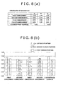
- FIG. 8 (a) is a chart that shows stress ratios for each specified portion when the stress generated in portion A of the conventional example is set at 1.
- FIG. 8 (b) is a bar graph that shows stress ratios of each specified portion.
- the second embodiment is compared to the conventional example, stress in the specified portion C (the first curved portion 23a) and stress in the specified portion A (the cut back portion 14b) are both reduced. Moreover, with the second embodiment, diffusion of stress occurs efficiently in the specified portion B (the second curved portion 23b), as well as in the specified portions A and C.
- the stress in the specified portion C (the first curved portion 33a) and the stress in the specified portion A (the cut back portion 14b) are both substantially reduced.
- the stress generated in the specified portion C (the first curved portion 33a) is reduced.
- substantial stress is generated in the specified portion B (the second curved portion 33b).
- this stress is less than the stress of the specified portion A (the cut back portion 104b) of the conventional example.
- Comparison of the fourth embodiment and the conventional example shows that stress in the specified portion A (the cut back portion 14b) is reduced. Moreover, with the fourth embodiment, the diffusion of stress occurs efficiently in the specified portion B (the second curved portion 43b), as well as in the specified portions A and C.
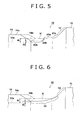
- a curved portion 53 extends continuously and is interposed between the cut back portion 14b of the splined portion 14 and the small diameter end portion of the tapered portion 12. In other words, one curved portion is provided between the cut back portion 14b and the tapered portion 12.
- An end portion of the curved portion 53 at the large diameter portion 11 side is formed so as to have a larger diameter with respect to (distance from) the shaft axis of the shank 10 than the cut back portion 14b.
- FIG. 6 the externality of the conventional shaft, which is configured by splined portion 104 and small diameter portion 103, is indicated by two-dotted chain line. Further, text H indicates the size of the small diameter portion 103 of the conventional shaft.
- the cut back portion 14b formed at the end portion of the splined portion 14 at the large diameter portion 11 side and the small diameter end portion of the tapered portion 12 are connected by the single curved portion 53. Accordingly, it is possible to efficiently disperse the stress between the cut back portion 14b formed at the end portion of the groove portion 14a at the large diameter portion 11 side, and the small diameter end portion of the tapered portion 12.
- a shaft has a shank with a splined portion and a large diameter portion formed in an outer peripheral surface of the shank, the large diameter portion having a diameter that is larger than a diameter of an external periphery of the splined portion.
- a tapered portion is provided at a side surface of the large diameter portion on the splined portion side. This tapered portion stops a fitting member that is fitted onto the splined portion.
- a cut back portion formed at an end portion of the splined portion at the large diameter portion side and the tapered portion are interposed by and continuously connected by a first curved portion, a flat portion and a second curved portion.
Landscapes
- Engineering & Computer Science (AREA)
- General Engineering & Computer Science (AREA)
- Mechanical Engineering (AREA)
- Ocean & Marine Engineering (AREA)
- Shafts, Cranks, Connecting Bars, And Related Bearings (AREA)
- Forging (AREA)
Applications Claiming Priority (2)
| Application Number | Priority Date | Filing Date | Title |
|---|---|---|---|
| JP2002286481 | 2002-09-30 | ||
| JP2002286481A JP4313014B2 (ja) | 2002-09-30 | 2002-09-30 | シャフト及びその製造方法 |
Publications (2)
| Publication Number | Publication Date |
|---|---|
| EP1403537A1 true EP1403537A1 (fr) | 2004-03-31 |
| EP1403537B1 EP1403537B1 (fr) | 2015-11-11 |
Family
ID=31973419
Family Applications (1)
| Application Number | Title | Priority Date | Filing Date |
|---|---|---|---|
| EP03021958.8A Expired - Fee Related EP1403537B1 (fr) | 2002-09-30 | 2003-09-29 | Arbre avec denture à cannelures et une rainure de décharge des contraintes et son procédé de fabrication |
Country Status (3)
| Country | Link |
|---|---|
| US (1) | US7052402B2 (fr) |
| EP (1) | EP1403537B1 (fr) |
| JP (1) | JP4313014B2 (fr) |
Cited By (4)
| Publication number | Priority date | Publication date | Assignee | Title |
|---|---|---|---|---|
| EP1533534A1 (fr) * | 2003-11-19 | 2005-05-25 | Ntn Corporation | Liaison arbre-moyeu pour arbre à transmission de puissance. |
| EP2728222A1 (fr) * | 2011-06-29 | 2014-05-07 | Toyota Jidosha Kabushiki Kaisha | Structure ajustée à serrage et procédé d'ajustement à serrage |
| CN105903867A (zh) * | 2015-02-19 | 2016-08-31 | 加特可株式会社 | 花键轴及其制造方法 |
| US11332913B2 (en) * | 2017-04-26 | 2022-05-17 | Brasscraft Manufacturing Company | Universal faucet handles |
Families Citing this family (7)
| Publication number | Priority date | Publication date | Assignee | Title |
|---|---|---|---|---|
| US7285052B1 (en) * | 2002-08-19 | 2007-10-23 | Sennax Industries, Inc. | Intermediate shaft assembly |
| US8043023B2 (en) * | 2003-08-07 | 2011-10-25 | Honda Motor Co., Ltd. | Power transmission mechanism of shaft and hub |
| US7972078B2 (en) * | 2003-08-07 | 2011-07-05 | Honda Motor Co., Ltd. | Power transmission mechanism of shaft and hub |
| US7821473B2 (en) | 2007-05-15 | 2010-10-26 | Toyota Motor Engineering & Manufacturing North America, Inc. | Gradient index lens for microwave radiation |
| JP2011094700A (ja) * | 2009-10-29 | 2011-05-12 | Ntn Corp | 中空シャフトおよび等速自在継手 |
| JP7402846B2 (ja) | 2021-09-10 | 2023-12-21 | ダイハツ工業株式会社 | 動力伝達装置 |
| CN113883021A (zh) * | 2021-10-29 | 2022-01-04 | 新疆金风科技股份有限公司 | 一种轴结构、风力发电机组轴系和风力发电机组 |
Citations (7)
| Publication number | Priority date | Publication date | Assignee | Title |
|---|---|---|---|---|
| US3024626A (en) * | 1959-10-02 | 1962-03-13 | Eaton Mfg Co | Axle shaft |
| US4275571A (en) * | 1978-04-14 | 1981-06-30 | Lohr & Bromkamp | Homokinetic universal joint |
| JPS5741840A (en) * | 1980-08-27 | 1982-03-09 | Nachi Fujikoshi Corp | Tool and method for rolling of spline or the like |
| JPH0942303A (ja) * | 1995-08-01 | 1997-02-10 | Ntn Corp | 等速自在継手 |
| EP1016801A1 (fr) * | 1998-07-22 | 2000-07-05 | Ntn Corporation | Mecanisme de transmission de puissance |
| JP2001206004A (ja) * | 2000-01-25 | 2001-07-31 | Nsk Ltd | 車輪駆動用軸受ユニット |
| US6319337B1 (en) * | 1999-02-10 | 2001-11-20 | Ntn Corporation | Power transmission shaft |
Family Cites Families (11)
| Publication number | Priority date | Publication date | Assignee | Title |
|---|---|---|---|---|
| US2714809A (en) * | 1952-02-06 | 1955-08-09 | Simmons Nat Bank | Washing machine agitator shafts |
| US3832076A (en) * | 1972-09-25 | 1974-08-27 | Gen Motors Corp | Splined assembly with retaining rings |
| US3888128A (en) * | 1974-05-31 | 1975-06-10 | Ammco Tools Inc | Wheel balancing system |
| GB1471706A (en) * | 1974-10-30 | 1977-04-27 | Chrysler Uk | Balancing rotors |
| FR2375429A1 (fr) * | 1975-08-13 | 1978-07-21 | Eurotungstene | Tige allonge composite pour forage avec marteau hors de trou |
| DE3009277C2 (de) * | 1980-03-11 | 1984-12-20 | Löhr & Bromkamp GmbH, 6050 Offenbach | Gelenkwelle |
| US4440123A (en) * | 1982-01-28 | 1984-04-03 | General Motors Corporation | Half speed balancer |
| US4552544A (en) * | 1982-12-27 | 1985-11-12 | Dana Corporation | Drive line slip joint assembly |
| DE19604160C1 (de) * | 1996-02-06 | 1997-05-28 | Freudenberg Carl Fa | Drehzahladaptiver Tilger |
| DE19635797C2 (de) * | 1996-06-12 | 2003-02-27 | Zf Sachs Ag | Torsionsschwingungsdämpfer mit Wälzkörpern als Koppelelemente |
| US6871719B2 (en) * | 2001-12-27 | 2005-03-29 | Torque-Traction Technologies, Inc. | Drive train member having convex splines |
-
2002
- 2002-09-30 JP JP2002286481A patent/JP4313014B2/ja not_active Expired - Fee Related
-
2003
- 2003-09-29 EP EP03021958.8A patent/EP1403537B1/fr not_active Expired - Fee Related
- 2003-09-30 US US10/673,155 patent/US7052402B2/en not_active Expired - Lifetime
Patent Citations (7)
| Publication number | Priority date | Publication date | Assignee | Title |
|---|---|---|---|---|
| US3024626A (en) * | 1959-10-02 | 1962-03-13 | Eaton Mfg Co | Axle shaft |
| US4275571A (en) * | 1978-04-14 | 1981-06-30 | Lohr & Bromkamp | Homokinetic universal joint |
| JPS5741840A (en) * | 1980-08-27 | 1982-03-09 | Nachi Fujikoshi Corp | Tool and method for rolling of spline or the like |
| JPH0942303A (ja) * | 1995-08-01 | 1997-02-10 | Ntn Corp | 等速自在継手 |
| EP1016801A1 (fr) * | 1998-07-22 | 2000-07-05 | Ntn Corporation | Mecanisme de transmission de puissance |
| US6319337B1 (en) * | 1999-02-10 | 2001-11-20 | Ntn Corporation | Power transmission shaft |
| JP2001206004A (ja) * | 2000-01-25 | 2001-07-31 | Nsk Ltd | 車輪駆動用軸受ユニット |
Non-Patent Citations (3)
| Title |
|---|
| PATENT ABSTRACTS OF JAPAN vol. 006, no. 113 (M - 138) 24 June 1982 (1982-06-24) * |
| PATENT ABSTRACTS OF JAPAN vol. 1997, no. 06 30 June 1997 (1997-06-30) * |
| PATENT ABSTRACTS OF JAPAN vol. 2000, no. 24 11 May 2001 (2001-05-11) * |
Cited By (9)
| Publication number | Priority date | Publication date | Assignee | Title |
|---|---|---|---|---|
| EP1533534A1 (fr) * | 2003-11-19 | 2005-05-25 | Ntn Corporation | Liaison arbre-moyeu pour arbre à transmission de puissance. |
| US7374493B2 (en) | 2003-11-19 | 2008-05-20 | Ntn Corporation | Power transmission shaft |
| EP2065605A3 (fr) * | 2003-11-19 | 2010-01-27 | Ntn Corporation | Une méthode de fabrication d'un arbre de transmission |
| EP2728222A1 (fr) * | 2011-06-29 | 2014-05-07 | Toyota Jidosha Kabushiki Kaisha | Structure ajustée à serrage et procédé d'ajustement à serrage |
| EP2728222A4 (fr) * | 2011-06-29 | 2015-04-22 | Toyota Motor Co Ltd | Structure ajustée à serrage et procédé d'ajustement à serrage |
| US9546725B2 (en) | 2011-06-29 | 2017-01-17 | Toyota Jidosha Kabushiki Kaisha | Press-fit structure and press-fit method |
| CN105903867A (zh) * | 2015-02-19 | 2016-08-31 | 加特可株式会社 | 花键轴及其制造方法 |
| CN105903867B (zh) * | 2015-02-19 | 2018-04-03 | 加特可株式会社 | 花键轴及其制造方法 |
| US11332913B2 (en) * | 2017-04-26 | 2022-05-17 | Brasscraft Manufacturing Company | Universal faucet handles |
Also Published As
| Publication number | Publication date |
|---|---|
| EP1403537B1 (fr) | 2015-11-11 |
| JP4313014B2 (ja) | 2009-08-12 |
| US20040063506A1 (en) | 2004-04-01 |
| US7052402B2 (en) | 2006-05-30 |
| JP2004125000A (ja) | 2004-04-22 |
Similar Documents
| Publication | Publication Date | Title |
|---|---|---|
| KR100257554B1 (ko) | 확대된 그립 범위에 걸쳐 균일한 고클램프를 갖는 고강도 블라인드 볼트 | |
| US5779551A (en) | Rotational fixed connection | |
| EP1403537B1 (fr) | Arbre avec denture à cannelures et une rainure de décharge des contraintes et son procédé de fabrication | |
| JP5020149B2 (ja) | スプライン連結構造 | |
| US9308777B2 (en) | Bearing device for a wheel | |
| US7485044B2 (en) | Shaft assembly and method of manufacture thereof | |
| EP2806180A2 (fr) | Joint Rzeppa de support de pignon direct | |
| EP2105321B1 (fr) | Ensemble de roulement de roue et son procédé de fabrication | |
| US20080104844A1 (en) | Method for Producing a Joint Connection and Joint Connection | |
| EP2565051A2 (fr) | Dispositif de support à roues | |
| EP1016801B1 (fr) | Mecanisme de transmission de puissance | |
| US11692592B2 (en) | Propeller shaft and production method for same | |
| CA1251962A (fr) | Organe d'assemblage filete, de longueur et masse reduites, et sa fabrication | |
| CN106414140B (zh) | 轻量驱动轮轴轴杆 | |
| KR101438015B1 (ko) | 차륜용 베어링 장치 | |
| US20190078609A1 (en) | Shaft | |
| EP2299134B1 (fr) | Joint homocinétique du type fixe | |
| JP2022502612A (ja) | 2ピース高強度ねじ | |
| JP5283832B2 (ja) | 等速自在継手 | |
| US20210372482A1 (en) | Power transmission shaft and method for manufacturing the same | |
| EP1536150A1 (fr) | Configuration pour serrage de vis, vis et outil de serrage de vis | |
| JPH08105307A (ja) | 部品圧入カムシャフト | |
| JP3816130B2 (ja) | 回転防止装置付き高強度トルク型ブラインドボルト | |
| DE102020201879B4 (de) | Gleichlaufgelenkbauteil mit Innenpassverzahnung und Verfahren zur Herstellung eines gehärteten Bauteils mit Innenpassverzahnung | |
| JP7235182B1 (ja) | ボールねじ装置およびその製造方法 |
Legal Events
| Date | Code | Title | Description |
|---|---|---|---|
| PUAI | Public reference made under article 153(3) epc to a published international application that has entered the european phase |
Free format text: ORIGINAL CODE: 0009012 |
|
| AK | Designated contracting states |
Kind code of ref document: A1 Designated state(s): AT BE BG CH CY CZ DE DK EE ES FI FR GB GR HU IE IT LI LU MC NL PT RO SE SI SK TR |
|
| AX | Request for extension of the european patent |
Extension state: AL LT LV MK |
|
| 17P | Request for examination filed |
Effective date: 20040809 |
|
| AKX | Designation fees paid |
Designated state(s): DE FR GB |
|
| RAP1 | Party data changed (applicant data changed or rights of an application transferred) |
Owner name: JTEKT CORPORATION |
|
| RIN1 | Information on inventor provided before grant (corrected) |
Inventor name: ICHIKAWA, KAZUYUKI Inventor name: OHWAKI, TOMONORI Inventor name: YAMATO, HIROKI |
|
| 17Q | First examination report despatched |
Effective date: 20080804 |
|
| RIC1 | Information provided on ipc code assigned before grant |
Ipc: F16D 1/10 20060101ALI20150331BHEP Ipc: F16C 3/02 20060101AFI20150331BHEP Ipc: F16D 3/20 20060101ALN20150331BHEP Ipc: F16D 1/06 20060101ALI20150331BHEP |
|
| GRAP | Despatch of communication of intention to grant a patent |
Free format text: ORIGINAL CODE: EPIDOSNIGR1 |
|
| RIC1 | Information provided on ipc code assigned before grant |
Ipc: F16C 3/02 20060101AFI20150508BHEP Ipc: F16D 1/06 20060101ALI20150508BHEP Ipc: F16D 1/10 20060101ALI20150508BHEP Ipc: F16D 3/20 20060101ALN20150508BHEP |
|
| INTG | Intention to grant announced |
Effective date: 20150601 |
|
| GRAS | Grant fee paid |
Free format text: ORIGINAL CODE: EPIDOSNIGR3 |
|
| GRAA | (expected) grant |
Free format text: ORIGINAL CODE: 0009210 |
|
| AK | Designated contracting states |
Kind code of ref document: B1 Designated state(s): DE FR GB |
|
| REG | Reference to a national code |
Ref country code: GB Ref legal event code: FG4D |
|
| REG | Reference to a national code |
Ref country code: DE Ref legal event code: R096 Ref document number: 60348233 Country of ref document: DE |
|
| REG | Reference to a national code |
Ref country code: DE Ref legal event code: R097 Ref document number: 60348233 Country of ref document: DE |
|
| REG | Reference to a national code |
Ref country code: FR Ref legal event code: PLFP Year of fee payment: 14 |
|
| PLBE | No opposition filed within time limit |
Free format text: ORIGINAL CODE: 0009261 |
|
| STAA | Information on the status of an ep patent application or granted ep patent |
Free format text: STATUS: NO OPPOSITION FILED WITHIN TIME LIMIT |
|
| 26N | No opposition filed |
Effective date: 20160812 |
|
| GBPC | Gb: european patent ceased through non-payment of renewal fee |
Effective date: 20160929 |
|
| PG25 | Lapsed in a contracting state [announced via postgrant information from national office to epo] |
Ref country code: GB Free format text: LAPSE BECAUSE OF NON-PAYMENT OF DUE FEES Effective date: 20160929 |
|
| REG | Reference to a national code |
Ref country code: FR Ref legal event code: PLFP Year of fee payment: 15 |
|
| PGFP | Annual fee paid to national office [announced via postgrant information from national office to epo] |
Ref country code: FR Payment date: 20170810 Year of fee payment: 15 |
|
| PG25 | Lapsed in a contracting state [announced via postgrant information from national office to epo] |
Ref country code: FR Free format text: LAPSE BECAUSE OF NON-PAYMENT OF DUE FEES Effective date: 20180930 |
|
| PGFP | Annual fee paid to national office [announced via postgrant information from national office to epo] |
Ref country code: DE Payment date: 20200916 Year of fee payment: 18 |
|
| REG | Reference to a national code |
Ref country code: DE Ref legal event code: R119 Ref document number: 60348233 Country of ref document: DE |
|
| PG25 | Lapsed in a contracting state [announced via postgrant information from national office to epo] |
Ref country code: DE Free format text: LAPSE BECAUSE OF NON-PAYMENT OF DUE FEES Effective date: 20220401 |