EP1403193B1 - Container for transporting valuable fragile objects - Google Patents
Container for transporting valuable fragile objects Download PDFInfo
- Publication number
- EP1403193B1 EP1403193B1 EP03017984A EP03017984A EP1403193B1 EP 1403193 B1 EP1403193 B1 EP 1403193B1 EP 03017984 A EP03017984 A EP 03017984A EP 03017984 A EP03017984 A EP 03017984A EP 1403193 B1 EP1403193 B1 EP 1403193B1
- Authority
- EP
- European Patent Office
- Prior art keywords
- vacuum insulation
- transport case
- insulation panels
- transport
- case according
- Prior art date
- Legal status (The legal status is an assumption and is not a legal conclusion. Google has not performed a legal analysis and makes no representation as to the accuracy of the status listed.)
- Expired - Lifetime
Links
Images


Classifications
-
- B—PERFORMING OPERATIONS; TRANSPORTING
- B65—CONVEYING; PACKING; STORING; HANDLING THIN OR FILAMENTARY MATERIAL
- B65D—CONTAINERS FOR STORAGE OR TRANSPORT OF ARTICLES OR MATERIALS, e.g. BAGS, BARRELS, BOTTLES, BOXES, CANS, CARTONS, CRATES, DRUMS, JARS, TANKS, HOPPERS, FORWARDING CONTAINERS; ACCESSORIES, CLOSURES, OR FITTINGS THEREFOR; PACKAGING ELEMENTS; PACKAGES
- B65D81/00—Containers, packaging elements, or packages, for contents presenting particular transport or storage problems, or adapted to be used for non-packaging purposes after removal of contents
- B65D81/02—Containers, packaging elements, or packages, for contents presenting particular transport or storage problems, or adapted to be used for non-packaging purposes after removal of contents specially adapted to protect contents from mechanical damage
- B65D81/05—Containers, packaging elements, or packages, for contents presenting particular transport or storage problems, or adapted to be used for non-packaging purposes after removal of contents specially adapted to protect contents from mechanical damage maintaining contents at spaced relation from package walls, or from other contents
- B65D81/127—Containers, packaging elements, or packages, for contents presenting particular transport or storage problems, or adapted to be used for non-packaging purposes after removal of contents specially adapted to protect contents from mechanical damage maintaining contents at spaced relation from package walls, or from other contents using rigid or semi-rigid sheets of shock-absorbing material
- B65D81/1275—Containers, packaging elements, or packages, for contents presenting particular transport or storage problems, or adapted to be used for non-packaging purposes after removal of contents specially adapted to protect contents from mechanical damage maintaining contents at spaced relation from package walls, or from other contents using rigid or semi-rigid sheets of shock-absorbing material laminated or bonded to the inner wall of a container
-
- B—PERFORMING OPERATIONS; TRANSPORTING
- B65—CONVEYING; PACKING; STORING; HANDLING THIN OR FILAMENTARY MATERIAL
- B65D—CONTAINERS FOR STORAGE OR TRANSPORT OF ARTICLES OR MATERIALS, e.g. BAGS, BARRELS, BOTTLES, BOXES, CANS, CARTONS, CRATES, DRUMS, JARS, TANKS, HOPPERS, FORWARDING CONTAINERS; ACCESSORIES, CLOSURES, OR FITTINGS THEREFOR; PACKAGING ELEMENTS; PACKAGES
- B65D85/00—Containers, packaging elements or packages, specially adapted for particular articles or materials
- B65D85/30—Containers, packaging elements or packages, specially adapted for particular articles or materials for articles particularly sensitive to damage by shock or pressure
Definitions
- the invention relates to an art object transport box for transporting high-quality, highly sensitive art objects, in particular paintings, having the features of the preamble of claim 1.
- the EP 0 636 546 A2 describes as a special protective measure a combination of a special transport holder for painting frames and a separate transport box, in which the transport bracket is installed. Such a transport box with internal transport holder can then be used in turn in an outer transport box, which in turn is lined with shock absorbing materials, in particular foam plastic materials. From this known transport box for transporting high-quality, highly sensitive objects, the invention proceeds.
- shock absorption systems of different types all of which have the purpose to suspend the highly sensitive object as low as possible mechanical loads during transport.
- the interior of a transport box with an insulating material eg. As one consisting of compressed wood fibers insulation board, lining a fiber board, which also regulates the humidity in the interior of the box.
- Vacuum insulation panels are film-coated, evacuated thermal insulation panels (EP-A-1 177 984 ), the core of which is regularly an open-pore polyurethane or polystyrene foam (EP-A-1 160 524 ) or honeycomb-like made of thermoplastic material ( US-A-5,316,171 ).
- the teaching of the present invention is based on the problem, the known, initially explained art object transport box to design such that the transported, high-quality and highly sensitive art object, such. For example, a framed painting is protected from exposure to extreme cold or heat for a significant period of time.
- object-Transporikiste invention under the particular aspect of fire protection vacuum insulation panels are used, which consist in the core of pressed into a plate silica powder (silica material) with embedded fiber materials.
- the pressure stable core is wrapped with a non-woven material used for pressure distribution and finally closed with a high-vacuum-tight and in particular metallized plastic film.
- the high-vacuum-tight, fully welded outer foil prevents new air entry into the core of the vacuum insulation panel.
- vacuum insulation panels have been known for many years. In the field of art object transport boxes for transporting high-quality, highly sensitive art objects, vacuum insulation panels have hitherto not been used.
- Vacuum insulation panels have standard thicknesses of 10 to 20 mm up to 40 mm. You can therefore be used to save space in the generic transport crates. If the shell is undamaged, a thermal conductivity below 0.005 W / mK is achieved. That's a tenth of the thermal conductivity of conventional insulation materials. Even if the high-vacuum-tight casing is damaged, the thermal conductivity at approx. 0.02 W / mK is only half that of conventional insulating materials such as foam or mineral fiber. The interior of the transport box, in which the highly sensitive object is located, is thus much better protected by vacuum insulation panels against temperature changes in the environment than by conventional insulation materials.
- vacuum insulation panels also in terms of fire protection.
- the core of vacuum insulation panels can have significant temperature resistance.
- the high-sensitive object located in the interior is thus protected over a considerable period of time from the direct action of flames, even if in the event of fire, of course, a significant increase in temperature in the interior can not be avoided. Rescue operations for such an object can thus be carried out before the object itself is seriously damaged.
- the vacuum insulation panels with a core of microporous silica Silica powders have the same chemical structure as sand. Through a suitable manufacturing process For example, extremely fine-grained powder particles having an amorphous structure can be produced. A pressed into a plate silica powder with embedded fiber materials therefore has cavities in the highly porous structure, which are smaller by a factor of 20 to 100 than in all other materials. Thus, the vacuum requirements of the vacuum insulation panel are much lower than in the prior art. Already with a rough vacuum of 10 to 100 mbar one can achieve a very low thermal conductivity. Of particular importance in this case is the high temperature resistance of the pressed silica powder, which still guarantees serious fire protection for the highly sensitive object located inside the transport box at up to 1,000 ° C., even if the plastic material forming the envelope has long been incinerated.
- the transportable, high-quality and highly sensitive object is stored directly in the transport box according to the invention, or whether there is still a separate box for receiving the object within the transport box according to the invention. It can therefore also be provided that the object is first packaged in a known transport bracket or crate and this is then taken up by the transport box according to the invention.
- Fig. 1 shows a perspective view of a known from the prior art transport box 1 with a transport holder 2 arranged therein for receiving a framed painting (see EP 0 636 546 A2 ).
- transport box 1 is composed of a frame with four walls 3, one of a board and four triangular boards formed, forming the bottom wall 4, on which the transport bracket 2 is mounted, and a (not shown) forming the lid wall. 5
- no completely closed bottom 4 is provided in the transport box 1 shown.
- transport crates 1 are known in which the bottom is formed by a completely closed wall 4. The latter embodiment represents the starting point for the present invention.
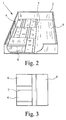
- Fig. 2 shows a perspective view of a preferred embodiment of the transport box according to the invention 1.
- the transport box 1 according to the invention consists of a frame consisting of four walls 3, a wall forming the bottom 4 and a (not shown) the Cover forming wall 5 together.
- the frame of the transport box 1 is ultimately formed from exactly four walls 3 or from a different number of walls 3, is not important.
- a framed painting is generally rectangular, a four-walled frame 3 is preferred. It is crucial that the transport box is completely closed, the walls 3, 4 thus adjacent to each other flush.
- illustrated transport box 1 can both for receiving a separate Transport bracket 2 and another transport box serve as well as the object to be transported record directly.
- the transport box 1 is already partially lined on its inside with vacuum insulation panels 6.
- the vacuum insulation panels 6 are arranged directly on the walls 3, 4.
- other materials such as insulation boards or a layer of foam plastic are arranged.
- the vacuum insulation panels 6 are arranged in two layers, in such a way that the joints 7 are displaced from one position relative to the joints 7 of the adjacent layer. In special cases, several layers may be provided. It is also possible to line the interior of the transport box 1 with only a single layer of vacuum insulation panels 6. However, a multi-layer insulation layer with mutually offset joints 7 has the advantage that on the one hand thermal bridges are largely avoided and on the other hand, the fire behavior is significantly improved. Through several layers of vacuum insulation panels 6, the insulation safety of the transport box 1 can be increased, since at a possible panel defect still dam the underlying or underlying vacuum insulation panels 6.
- FIG. 3 an example is shown in a plan view how vacuum insulation panels 6 in the transport box 1 can be arranged one above the other.
- the upper layer of vacuum insulation panels 6 is rotated at an angle of 90 ° to the underlying layer. It can be clearly seen that the joint 7 between the two underlying vacuum insulation panels 6 is almost completely covered by the upper layer (dashed line). But it is also possible that the vacuum insulation panels 6 of the upper layer arranged in parallel alignment with those of the lower layer, but laterally offset therefrom (see Fig. 2 ). Other possibilities are also conceivable, as long as the joints 7 a layer are covered by the vacuum insulation panels 6 another location.
- edges 8 of the transport box 1 ie the area in which two walls, for example, the wall forming the bottom 4 and a wall 3 of the frame, adjacent to each other. Also in this area, the vacuum insulation panels 6 should be arranged so that thermal bridges are largely avoided. Examples of optimal arrangements of vacuum insulation panels 6 in the region of the edges 8 show the Fig. 4a ) and b).
- Fig. 4a the edge 8 between the two walls 3 and 4 arranged at right angles to each other is shown in cross-section.
- a vertical vacuum insulation panel 6 was first attached to the wall 3 so that its end face 9 touches the wall 4 forming the bottom.
- another vacuum insulation panel 6 was placed flat on the wall 4 and pushed so far to the left until it rests flush against the side surface of the first attached vacuum insulation panel 6.
- a second layer of vacuum insulation panels 6 was arranged in a corresponding manner.
- the end face 9 of the arranged on one wall vacuum insulation panel 6 touches the side surface of the arranged on the other wall vacuum insulation panel 6. In this way, so also in the edge and corner of the transport box 1 thermal bridges are avoided, whereby the insulation and ultimately the fire behavior can be improved.
- Fig. 4b shows a variant of the in Fig. 4a ) arrangement of the vacuum insulation panels 6 in the region of the edge 8 between the wall 3 and the wall 4.
- the vacuum insulation panels 6 can also be arranged on all other edges 8 of the transport box 1.
- the vacuum insulation panels 6 are glued in particular there. Furthermore, it is expedient to protect the vacuum insulation panels 6 of two adjacent layers from slipping. For this purpose, the layers are advantageously firmly connected to each other, in particular glued together. This also increases the stability of the transport box 1.
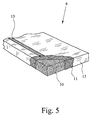
- a vacuum insulation panel 6 is shown.
- the core 10 of the vacuum insulation panel 6 may be made of a pyrogenic and / or a microporous Material, in particular of a silica material (silica powder, pressed) exist.
- a silica material silicon powder, pressed
- the use of this material allows the core 10 to be evacuated without the external loading pressure compressing the core 10.
- Especially silica material has the advantage that extremely fine-grained powder particles are produced with a glassy structure by a special manufacturing process, so that cavities in a highly porous structure arise during pressing into plates, which are smaller by a factor of 20 to 100 than in all other materials , such as B. organic foams.
- the compression of the fine-grained silica material is expediently done by embedding fiber material of appropriate consistency, so that the overall structure compact and coherent fails.
- silica material has the advantages of temperature resistance explained in the general part of the specification.
- vacuum insulation panels 6 with a core 10 made of open-cell polyurethane or polystyrene foams or glass fiber webs. Also such vacuum insulation panels 6 have a low thermal conductivity and keep the external load pressure.
- the pressed core 10 of in Fig. 5 illustrated vacuum insulation panel 6 is initially covered by a nonwoven layer 11, which is then surrounded by a metallized plastic film 12.
- the plastic film 12 is a special gas-tight film that is free of thermal bridges.
- Fig. 5 a tab-shaped weld 13 shown, which is provided due to the production of the plastic film 12. So that the vacuum insulation panels 6 in the transport box 1 adjoin one another optimally in order to achieve the lowest possible heat transfer at the joints 7, the tabs or welds 13 should not be arranged in the area in which the vacuum insulation panels 6 touch.
- the vacuum insulation panels 6 should therefore have a largely smooth surface in the region of the edge, possibly a flat weld seam. It is essential that there are no protruding tabs in the region of the edge which would prevent the immediately adjacent arrangement of adjacent insulation panels 6.
- a moisture-absorbing medium should be provided.
- These can be porous, z. B. of pressed wood fiber plates - namely so-called fiber insulation panels 14 - or be other body.
- a moisture-releasing medium may also be provided to prevent the transport goods from drying out. In this way, even with changing environmental conditions, the moisture in the interior of the transport box 1 can be kept relatively constant for a long time.
- the temperature stability inside the transport box 1 depends on how much heat-storing mass is present in the interior of the transport box.
- Heat-storing mass can be introduced by additionally existing internals, additional material layers and of course by the object itself, which has, for example, a solid frame.
- the highly sensitive object is still a very small object with little mass.
- Such materials are available per se on the market, they are introduced according to the invention targeted in the transport box to ensure an increased temperature stability in the interior for the highly sensitive object.
- a shock absorption system should be provided inside the transport box 1, which protects the object from shocks and shocks.
- one or more foam layers inside the Transport box 1 may be arranged. These may be provided between the walls 3, 5 and the vacuum insulation panels 6 and / or between the vacuum insulation panels 6 and the cargo. The foam layers can also additionally increase the thermal insulation.
- a shock absorption system will be understood to mean any construction that, in one way or another, supports the highly sensitive object to minimize mechanical stresses on the object.
- Fig. 6 shows a construction which is modified to take into account the high weight of the plates of the transport box 1 for large dimensions of several meters constructive.
- the surface 15 is divided by webs 16 in several, in particular in three fields 17, in which then arranged individual vacuum insulation panels 6, in turn are glued.
- the webs 16 are here sheathed with insulating material 18, to form the smallest possible thermal bridges (section, not to scale).
- tension straps o are also known, for fixing the vacuum insulation panels 6, so that their slippage and displacement is avoided.
- tension straps o are also known, for fixing the vacuum insulation panels 6, so that their slippage and displacement is avoided.
- tension straps o are also known, for fixing the vacuum insulation panels 6, so that their slippage and displacement is avoided.
- tension straps o are also known, for fixing the vacuum insulation panels 6, so that their slippage and displacement is avoided.
- tension straps o Provide, which are attached to the edges of the wall, in particular the lid 5.
Description
Die Erfindung betrifft eine Kunstobjekt-Transportkiste zum Transport hochwertiger, hochempfindlicher Kunstobjekte, insbesondere Gemälde, mit den Merkmalen des Oberbegriffs von Anspruch 1.The invention relates to an art object transport box for transporting high-quality, highly sensitive art objects, in particular paintings, having the features of the preamble of
Die Lehre der vorliegenden Erfindung wird nachfolgend anhand des bevorzugten Anwendungsgebietes für gerahmte Gemälde erläutert. Dabei ist aber stets im Auge zu behalten, daß die Lehre der Erfindung auch für andere entsprechend hochwertige und hochempfindliche Kunstobjekte wie Holztafeln, Altartafeln, Reliefdarstellungen und ggf. auch Statuetten, anwendbar ist.The teaching of the present invention will be explained below with reference to the preferred field of application for framed paintings. It should always be borne in mind, however, that the teaching of the invention is also applicable to other correspondingly high-quality and highly sensitive objects of art such as wooden panels, altar panels, relief representations and possibly also statuettes.
Zum Transport vom Gemälden in Gemälderahmen werden als Transporthalterungen aus Holz gefertigte, flache Kisten verwendet, in die das im Rahmen befindliche Gemälde in weichem Polstermaterial, insbesondere in Schaumkunststoff, eingelegt wird. Transportiert werden diese Kisten dann stehend. An allen Seiten ist das Gemälde dicht von Polstermaterial umgeben, um bei Schwingungen und Schlägen beim Transport nicht beschädigt zu werden.To transport the paintings in painting frames are made as transport holders made of wood, flat boxes used in which the paintings located in the frame in soft padding material, especially in foam plastic, is inserted. These boxes are then transported standing. On all sides the painting is surrounded by padding material so as not to be damaged during vibrations and impacts during transport.
Die
Für sich ist es bekannt, bei Transportkisten der in Rede stehenden Art Schockabsorptionssysteme unterschiedlicher Art einzusetzen, die alle den Zweck haben, das hochempfindliche Objekt möglichst geringen mechanischen Belastungen während des Transports auszusetzen.For itself, it is known to use in transport boxes of the type in question shock absorption systems of different types, all of which have the purpose to suspend the highly sensitive object as low as possible mechanical loads during transport.
Für sich ist es ferner bekannt, das Innere einer Transportkiste mit einem Dämmstoff, z. B. einer aus gepreßten Holzfasern bestehenden Dämmplatte, einer Faserdämmplatte auszukleiden, die auch die Luftfeuchte im Inneren der Kiste reguliert.For itself, it is also known, the interior of a transport box with an insulating material, eg. As one consisting of compressed wood fibers insulation board, lining a fiber board, which also regulates the humidity in the interior of the box.
Ein besonderes Problem bei den seit Jahrzehnten bekannten Kunstobjekt-Transportkisten zum Transport hochwertiger, hochempfindlicher Kunstobjekte stellt der Hitzeschutz, insbesondere der Brandschutz dar. Bislang ist man hier über einen Außenanstrich der äußeren Transportkiste mit Brandschutzfarbe nicht hinausgekommen. Aber auch ohne daß man von einer Brandsituation ausgeht, sind die bislang bekannten Transportkisten hinsichtlich der Beibehaltung einer bestimmten Temperatur im Inneren, wo sich das hochempfindliche Kunstobjekt befindet, nach wie vor problematisch. Man muß dabei bedenken, daß solche Transportkisten beim Transport zwischen den Kontinenten beispielsweise durch Wartezeiten auf Flughäfen etc. großen Schwankungen der Außentemperatur ausgesetzt sind. Bislang ist es nicht gelungen, Transportkisten der in Rede stehenden Art derart auszugestalten, daß sie im Inneren eine hinreichend konstante Temperatur für das hochempfindliche Kunstobjekt bereitstellen.A particular problem with the well-known for decades art object transport boxes for transporting high-quality, highly sensitive art objects is the heat protection, in particular the fire protection. So far, one has not come out here on an exterior painting of the outer transport box with fire protection paint. But even without assuming a fire situation, the previously known transport crates are still problematic in terms of maintaining a certain temperature in the interior, where the highly sensitive art object is located. One must remember that such transport crates are exposed during transport between the continents, for example by waiting at airports, etc. large fluctuations in the outside temperature. So far, it has not been possible to design transport boxes of the type in question such that they provide a sufficiently constant inside temperature for the highly sensitive art object.
Auch zum Transport von Kunstobjekten geeignete Transportkisten sind bekannt, die innen mit sog. Vakuumisolationspaneelen mehr oder weniger vollflächig ausgekleidet sind (
Der Lehre der vorliegenden Erfindung liegt das Problem zugrunde, die bekannte, eingangs erläuterte Kunstobjekt-Transportkiste derart auszugestalten, daß das zu transportierende, hochwertige und hochempfindliche Kunstobjekt, z. B. ein gerahmtes Gemälde, vor der Einwirkung von extremer Kälte oder Hitze über einen erheblichen Zeitraum hinweg geschützt ist.The teaching of the present invention is based on the problem, the known, initially explained art object transport box to design such that the transported, high-quality and highly sensitive art object, such. For example, a framed painting is protected from exposure to extreme cold or heat for a significant period of time.
Das zuvor aufgezeigte Problem ist bei einer Kunstobjekt-Transportkiste mit den Merkmalen des Oberbegriffs von Anspruch 1 durch die Merkmale des kennzeichnenden Teils von Anspruch 1 gelöst.The above-mentioned problem is solved in an art object transport box having the features of the preamble of
Für den Einsatz bei der erfindungsgemäßen Kunstobjekt-Transporikiste unter dem besonderen Aspekt des Brandschutzes werden Vakuumisolationspaneele verwendet, die im Kern aus zu einer Platte verpreßtem Kieselsäurepulver (Silica-Material) mit eingebetteten Fasermaterialien bestehen. Der druckstabile Kern wird mit einem der Druckverteilung dienenden Vliesmaterial umhüllt und abschließend mit einer hochvakuumdichtenund insbesondere metallisierten Kunststoffolie verschlossen. Die hochvakuumdichte, vollständig verschweißte Außenfolie verhindert einen erneuten Luftzutritt in den Kern des Vakuumisolationspaneels.For use in the art object-Transporikiste invention under the particular aspect of fire protection vacuum insulation panels are used, which consist in the core of pressed into a plate silica powder (silica material) with embedded fiber materials. The pressure stable core is wrapped with a non-woven material used for pressure distribution and finally closed with a high-vacuum-tight and in particular metallized plastic film. The high-vacuum-tight, fully welded outer foil prevents new air entry into the core of the vacuum insulation panel.
Vakuumisolationspaneele sind zwar seit vielen Jahren bekannt. Auf dem Gebiet der Kunstobjekt-Transportkisten zum Transport hochwertiger, hochempfindlicher Kunstobjekte haben Vakuumisolationspaneele bislang keine Anwendung gefunden.Although vacuum insulation panels have been known for many years. In the field of art object transport boxes for transporting high-quality, highly sensitive art objects, vacuum insulation panels have hitherto not been used.
Vakuumisolationspaneele haben Standarddicken von 10 bis 20 mm bis zu 40 mm. Sie können aus diesem Grunde platzsparend in den gattungsgemäßen Transportkisten eingesetzt werden. Bei unbeschädigter Hülle wird eine Wärmeleitfähigkeit unter 0,005 W/mK erzielt. Das ist ein Zehntel der Wärmeleitfähigkeit herkömmlicher Dämmstoffe. Auch bei Beschädigung der hochvakuumdichten Hülle ist die Wärmeleitfähigkeit mit ca. 0,02 W/mK noch lediglich halb so groß wie bei herkömmlichen Dämmstoffen wie Schaumstoff oder Mineralfaser. Das Innere der Transportkiste, in dem sich das hochempfindliche Objekt befindet, ist also durch Vakuumisolationspaneele gegen Temperaturänderungen in der Umgebung deutlich besser geschützt als durch herkömmliche Dämmstoffe.Vacuum insulation panels have standard thicknesses of 10 to 20 mm up to 40 mm. You can therefore be used to save space in the generic transport crates. If the shell is undamaged, a thermal conductivity below 0.005 W / mK is achieved. That's a tenth of the thermal conductivity of conventional insulation materials. Even if the high-vacuum-tight casing is damaged, the thermal conductivity at approx. 0.02 W / mK is only half that of conventional insulating materials such as foam or mineral fiber. The interior of the transport box, in which the highly sensitive object is located, is thus much better protected by vacuum insulation panels against temperature changes in the environment than by conventional insulation materials.
Von besonderer Bedeutung ist der Einsatz von Vakuumisolationspaneelen auch unter dem Aspekt des Brandschutzes. Der Kern von Vakuumisolationspaneelen kann eine erhebliche Temperaturbeständigkeit aufweisen. Das im Innenraum befindliche hochempfindliche Objekt ist also über einen erheblichen Zeitraum vor einer unmittelbaren Einwirkung von Flammen geschützt, auch wenn im Brandfall natürlich ein deutlicher Temperaturanstieg im Innenraum nicht zu vermeiden ist. Rettungsmaßnahmen für ein solches Objekt können also durchgeführt werden, bevor das Objekt selbst ernsthaft beschädigt wird.Of particular importance is the use of vacuum insulation panels also in terms of fire protection. The core of vacuum insulation panels can have significant temperature resistance. The high-sensitive object located in the interior is thus protected over a considerable period of time from the direct action of flames, even if in the event of fire, of course, a significant increase in temperature in the interior can not be avoided. Rescue operations for such an object can thus be carried out before the object itself is seriously damaged.
Besondere Bedeutung kommt der Ausführung der Vakuumisolationspaneele mit einem Kern aus mikroporöser Kieselsäure zu. Kieselsäurepulver haben die gleiche chemische Struktur wie Sand. Durch einen passenden Herstellungsprozeß können extrem feinkörnige Pulverteilchen mit einer amorphen Struktur erzeugt werden. Ein zu einer Platte verpreßtes Kieselsäurepulver mit eingebetteten Fasermaterialien weist daher Hohlräume in der hochporösen Struktur auf, die um den Faktor 20 bis 100 kleiner sind als bei allen anderen Materialien. Somit sind die Anforderungen an das Vakuum des Vakuumisolationspaneels wesentlich geringer als im Stand der Technik. Bereits mit einem Grobvakuum von 10 bis 100 mbar kann man eine sehr geringe Wärmeleitfähigkeit erreichen. Von besonderer Bedeutung ist dabei die hohe Temperaturbeständigkeit des verpreßten Kieselsäurepulvers, die mit bis zu 1.000 °C einen ernsthaften Brandschutz für das im Inneren der Transportkiste befindliche hochempfindliche Objekt auch dann noch gewährleistet, wenn im übrigen das die Hülle bildende Kunststoffmaterial längst verbrannt ist.Of particular importance is the design of the vacuum insulation panels with a core of microporous silica. Silica powders have the same chemical structure as sand. Through a suitable manufacturing process For example, extremely fine-grained powder particles having an amorphous structure can be produced. A pressed into a plate silica powder with embedded fiber materials therefore has cavities in the highly porous structure, which are smaller by a factor of 20 to 100 than in all other materials. Thus, the vacuum requirements of the vacuum insulation panel are much lower than in the prior art. Already with a rough vacuum of 10 to 100 mbar one can achieve a very low thermal conductivity. Of particular importance in this case is the high temperature resistance of the pressed silica powder, which still guarantees serious fire protection for the highly sensitive object located inside the transport box at up to 1,000 ° C., even if the plastic material forming the envelope has long been incinerated.
Für die Lehre der vorliegenden Erfindung ist es nicht von Bedeutung, ob das zu transportierende, hochwertige und hochempfindliche Objekt unmittelbar in der erfindungsgemäßen Transportkiste gelagert ist, oder ob sich innerhalb der erfindungsgemäßen Transportkiste noch eine separate Kiste zur Aufnahme des Objekts befindet. Es kann also auch vorgesehen sein, daß das Objekt zunächst in einer an sich bekannten Transporthalterung oder -kiste verpackt wird und diese anschließend von der erfindungsgemäßen Transportkiste aufgenommen wird.For the teaching of the present invention, it does not matter whether the transportable, high-quality and highly sensitive object is stored directly in the transport box according to the invention, or whether there is still a separate box for receiving the object within the transport box according to the invention. It can therefore also be provided that the object is first packaged in a known transport bracket or crate and this is then taken up by the transport box according to the invention.
Im übrigen sind bevorzugte Ausgestaltungen und Weiterbildungen der Lehre Gegenstand der weiteren Unteransprüche.Moreover, preferred embodiments and further developments of the teaching are the subject of the further subclaims.
Im folgenden wird die Erfindung anhand einer lediglich bevorzugte Ausführungsbeispiele darstellenden Zeichnung näher erläutert. In der Zeichnung zeigt
- Fig. 1
- in einer perspektivischen Ansicht eine aus dem Stand der Technik bekannte Holz-Transportkiste mit eingebauter Transporthalterung,
- Fig. 2
- in einer perspektivischen Ansicht eine teilweise mit Vakuumisolationspaneelen ausgekleidete Transportkiste in einem bevorzugten Ausführungsbeispiel,
- Fig. 3
- in einer Draufsicht eine beispielhafte Anordnung von Vakuumisolationspaneelen,
- Fig. 4 a), b)
- in einer Schnittdarstellung zwei beispielhafte Anordnungen von Vakuumisolationspaneelen im Bereich der Kanten der erfindungsgemäßen Transportkiste,
- Fig. 5
- die einzelnen Materialschichten bei einem Ausführungsbeispiel eines Vakuumisolationspaneels,
- Fig. 6
- ein weiteres Ausführungsbeispiel einer erfindungsgemäßen Transportkiste, und zwar einen besonders großflächigen Deckel mit einer besonderen konstruktiven Ausgestaltung.
- Fig. 1
- in a perspective view of a known from the prior art wooden transport box with built-in transport bracket,
- Fig. 2
- in a perspective view of a partially lined with vacuum insulation panels transport box in a preferred embodiment,
- Fig. 3
- in a plan view an exemplary arrangement of vacuum insulation panels,
- Fig. 4 a), b)
- in a sectional view two exemplary arrangements of vacuum insulation panels in the region of the edges of the transport box according to the invention,
- Fig. 5
- the individual material layers in one embodiment of a vacuum insulation panel,
- Fig. 6
- a further embodiment of a transport box according to the invention, namely a particularly large-area lid with a special structural design.
Im dargestellten Ausführungsbeispiel ist die Transportkiste 1 bereits teilweise an ihrer Innenseite mit Vakuumisolationspaneelen 6 ausgekleidet. Beim dargestellten Ausführungsbeispiel sind die Vakuumisolationspaneele 6 unmittelbar an den Wänden 3, 4 angeordnet. Es ist aber denkbar, daß zwischen den Vakuumisolationspaneelen 6 und den Wänden 3, 4 noch andere Materialien, beispielsweise Dämmstoffplatten oder eine Lage Schaumkunststoff angeordnet sind.In the illustrated embodiment, the
Im vorliegenden Fall sind die Vakuumisolationspaneele 6 zweilagig angeordnet, und zwar derart, daß die Fugen 7 der einen Lage gegenüber den Fugen 7 der angrenzenden Lage versetzt sind. In besonderen Fällen können auch mehrere Lagen vorgesehen sein. Es ist auch möglich, den Innenraum der Transportkiste 1 mit nur einer einzigen Lage von Vakuumisolationspaneelen 6 auszukleiden. Allerdings hat eine mehrlagige Isolationsschicht mit zueinander versetzten Fugen 7 den Vorteil, daß einerseits thermische Brücken weitgehend vermieden werden und andererseits das Brandverhalten deutlich verbessert wird. Durch mehrere Lagen von Vakuumisolationspaneelen 6 kann auch die Dämmsicherheit der Transportkiste 1 gesteigert werden, da bei einem etwaigen Paneeldefekt immer noch die dahinterliegenden bzw. darunterliegenden Vakuumisolationspaneele 6 dämmen.In the present case, the
In
Das zuvor Gesagte gilt auch für die Kanten 8 der Transportkiste 1, d. h. den Bereich, in dem zwei Wände, beispielsweise die den Boden bildende Wand 4 und eine Wand 3 des Rahmens, aneinander angrenzen. Auch in diesem Bereich sollten die Vakuumisolationspaneele 6 so angeordnet werden, daß thermische Brükken weitgehend vermieden werden. Beispiele für optimale Anordnungen von Vakuumisolationspaneelen 6 im Bereich der Kanten 8 zeigen die
In
Um die Vakuumisolationspaneele 6 an den Wänden 3, 4, 5 zu befestigen, sind diese insbesondere dort angeklebt. Ferner ist es zweckmäßig auch die Vakuumisolationspaneele 6 zweier aneinander angrenzender Lagen vor einem Verrutschen zu schützen. Dazu sind die Lagen vorteilhafterweise fest miteinander verbunden, insbesondere miteinander verklebt. Dadurch wird außerdem die Stabilität der Transportkiste 1 erhöht.To attach the
In
Sollen allein die dämmtechnischen Eigenschaften, nicht aber die brandschutztechnischen Eigenschaften der Transportkiste 1 verbessert werden, so können auch Vakuumisolationspaneele 6 mit einem Kern 10 aus offenporigen Polyurethan- oder Polystyrolschäumen oder aus Glasfaservliesen gewählt werden. Auch solche Vakuumisolationspaneele 6 haben eine geringe Wärmeleitfähigkeit und halten den äußeren Belastungsdruck aus.If only the insulation properties, but not the fire protection properties of the
Der gepreßte Kern 10 des in
Ferner ist in
Damit während des Transports oder der Lagerung das gerahmte Gemälde oder ein sonstiges hochwertiges, hochempfindliches Objekt optimal vor übermäßiger Feuchtigkeit im Inneren der Transportkiste 1 geschützt ist, sollte ein Feuchtigkeit aufnehmendes Medium vorgesehen sein. Dies können poröse, z. B. aus gepreßter Holzfaser bestehende Platten - nämlich sogenannte Faserdämmplatten 14 - oder sonstige Körper sein. Wenn die Transportkiste 1 längere Zeit einer extrem trokkenen oder warmen Umgebung ausgesetzt ist, kann zur Vermeidung des Austrocknens des Transportguts auch ein Feuchtigkeit abgebendes Medium vorgesehen sein. Auf diese Weise kann auch bei sich ändernden Umgebungsbedingungen die Feuchtigkeit im Inneren der Transportkiste 1 über längere Zeit relativ konstant gehalten werden.So that the framed painting or another high-quality, highly sensitive object is optimally protected against excessive moisture inside the
Bereits oben ist umfangreich erläutert worden, daß es bei bestimmten hochempfindlichen Objekten darauf ankommen kann, die Temperatur im Inneren der Transportkiste 1 möglichst konstant zu halten. Es liegt auf der Hand, daß die Temperaturkonstanz im Inneren der Transportkiste 1 davon abhängt, wieviel wärmespeichernde Masse im Inneren der Transportkiste vorhanden ist. Wärmespeichernde Masse kann man durch zusätzlich vorhandene Einbauten, zusätzliche Materialschichten und natürlich auch durch das Objekt selbst, das beispielsweise einen massiven Rahmen aufweist, einbringen. Häufig ist aber das hochempfindliche Objekt auch noch ein sehr kleines, wenig Masse aufweisendes Objekt. Insbesondere in einem solchen Fall kann es sich empfehlen, gezielt im Inneren zusätzlich ein wärmespeicherndes Material vorzusehen. Dies ist insbesondere dann sehr effektiv, wenn es sich hier um ein Material handelt, das als Latentwärmespeicher wirkt, insbesondere auf der Basis eines Phasenwechsels. Solche Materialien sind an sich am Markt erhältlich, sie werden erfindungsgemäß gezielt in die Transportkiste eingebracht, um im Inneren für das hochempfindliche Objekt eine erhöhte Temperaturkonstanz zu gewährleisten.It has already been explained extensively that it may be important for certain highly sensitive objects to keep the temperature inside the
Bereits oben ist darauf hingewiesen worden, daß ein Kiste-In-Kiste-System vorgesehen werden kann. In einem solchen Fall empfiehlt es sich, daß mindestens eine Platte der inneren Transportkiste von einer Faserdämmplatte 14 gebildet ist.It has already been pointed out above that a box-in-box system can be provided. In such a case, it is recommended that at least one plate of the inner transport box is formed by a
Schließlich sollte im Inneren der Transportkiste 1 auch ein Schockabsorptionssystem vorgesehen sein, das das Objekt vor Erschütterungen und Schlägen schützt. Dazu können beispielsweise eine oder mehrere Schaumstofflagen im Inneren der Transportkiste 1 angeordnet sein. Diese können zwischen den Wänden 3, 5 und den Vakuumisolationspaneelen 6 und/oder zwischen den Vakuumisolationspaneelen 6 und dem Transportgut vorgesehen sein. Die Schaumstofflagen können aber auch zusätzlich noch die Wärmedämmung erhöhen. Letztlich wird man unter einem Schockabsorptionssystem jede Konstruktion verstehen können, die auf die eine oder andere Art das hochempfindliche Objekt so lagert, daß mechanische Beanspruchungen des Objekts minimiert werden.Finally, a shock absorption system should be provided inside the
Für sich ist es auch bekannt, zur Fixierung der Vakuumisolationspaneele 6, so daß deren Verrutschen und Verlagern vermieden wird, Spanngurte o. dgl. vorzusehen, die an den Rändern der Wand, insbesondere des Deckels 5, befestigt sind.It is also known, for fixing the
Claims (10)
- Art object transport case for the transport of valuable, highly sensitive art objects, comprising a frame which preferably consists of four walls (3), a wall (4) which forms the base, and a wall (5) which forms the lid, wherein the transport case (1) can be fully closed and is lined internally with vacuum insulation panels (6), which in the core (10) consist of pyrogenic silica powder, compressed into a board, with embedded fibre materials.
- Transport case according to Claim 1, characterized in that, in the region of two mutually adjoining walls (3, 4), the end face (9) of the vacuum insulation panels (6) disposed on one wall is in contact with the side face (9) of the vacuum insulation panels (6) disposed on the other wall.
- Transport case according to Claim 1 or 2, characterized in that at least two layers of vacuum insulation panels (6) are provided and are arranged such that the joints (7) of one layer are offset in relation to the joints (7) of the adjoining layer(s), and such that, preferably, the joints (7) of one layer run transversely to the joints (7) of the adjoining layer(s).
- Transport case according to one of Claims 1 to 3, characterized in that the vacuum insulation panels (6) are connected fixedly to the walls (3, 4, 5), in particular are glued to these, and in that, if present, the mutually adjoining layers are fixedly connected to one another, in particular are glued to one another.
- Transport case according to one of the preceding claims, characterized in that the vacuum insulation panels (6), in the region of the edge, have a continuously largely smooth surface, i.e. in the region of their edge have no protruding butt straps or weld seams (13).
- Transport case according to one of the preceding claims, characterized in that inside the transport case (1), within the interior enclosed by the vacuum insulation panels (6), a moisture-absorbing and/or moisture-releasing medium is provided, the moisture-absorbing and/or moisture-releasing medium preferably having at least one fibre insulating board (14).
- Transport case according to one of the preceding claims, characterized in that inside the transport case (1), within the interior enclosed by the vacuum insulation panels (6), a mass of sufficient heat-storing capacity, possibly a mass of additional heat-storing capacity in addition to the object itself, possibly in the form of a latent heat store, is provided, and/or in that inside the transport case (1), within the interior enclosed by the vacuum insulation panels (6), a shock absorption system is provided, on or in which the object to be transported is stored.
- Transport case according to one of the preceding claims, characterized in that inside the transport case (1) there is provided a transport case, once again closed, in which the object to be transported is stored, in particular in that the shock absorption system inside the transport case (1) is realized, for its part, as a closed transport case, the at least one fibre insulating board (14) preferably forming a board, in particular the lid, of the inner transport case.
- Transport case according to one of the preceding claims, characterized in that, between the walls (3, 5) of the transport case (1) and the vacuum insulation panels (6) and/or on the inner sides of the vacuum insulation panels (6), at least one layer of foamed plastic is provided.
- Transport case according to one of the preceding claims, characterized in that, if the dimensions of the walls, in particular of the base (4) or the lid (5), are particularly large, the area (15) is divided by crosspieces (16) into a plurality of, in particular three fields (17), in which individual vacuum insulation panels (6) are then disposed, in particular are glued in place, in that, on the inner side of the particularly large area lined with vacuum insulation panels (6), a stabilizing plate, in particular a fibre insulating board (14), is preferably disposed, in particular is attached to the crosspieces (16) and thus additionally fixes the vacuum insulation panels (6), and/or the crosspieces (16) are clad, at least on three sides, with insulating material (18), which is realized or equipped so as to be fire-retardant.
Applications Claiming Priority (4)
| Application Number | Priority Date | Filing Date | Title |
|---|---|---|---|
| DE20214927 | 2002-09-26 | ||
| DE20214927U | 2002-09-26 | ||
| DE20216474U | 2002-10-24 | ||
| DE20216474U DE20216474U1 (en) | 2002-09-26 | 2002-10-24 | Case for transporting valuable, highly sensitive objects, in particular, framed or otherwise form-stabilized paintings is internally lined with vacuum insulation panels |
Publications (2)
| Publication Number | Publication Date |
|---|---|
| EP1403193A1 EP1403193A1 (en) | 2004-03-31 |
| EP1403193B1 true EP1403193B1 (en) | 2008-06-11 |
Family
ID=31979687
Family Applications (1)
| Application Number | Title | Priority Date | Filing Date |
|---|---|---|---|
| EP03017984A Expired - Lifetime EP1403193B1 (en) | 2002-09-26 | 2003-08-07 | Container for transporting valuable fragile objects |
Country Status (3)
| Country | Link |
|---|---|
| US (1) | US7140508B2 (en) |
| EP (1) | EP1403193B1 (en) |
| DE (1) | DE50309971D1 (en) |
Families Citing this family (34)
| Publication number | Priority date | Publication date | Assignee | Title |
|---|---|---|---|---|
| DE202005011897U1 (en) * | 2005-07-26 | 2005-10-06 | Hasenkamp Internationale Transporte Gmbh | Transport box for picture frames and the like comprises a distance piece corresponding to the distance between the picture frame top element or a piece of cushioning material on this element and the box lid |
| US7597245B1 (en) | 2006-09-18 | 2009-10-06 | David Allen Tillery | Dental impression shipping box |
| US20090001086A1 (en) * | 2007-04-12 | 2009-01-01 | Nanopore, Inc. | Container insert incorporating thermally insulative panels |
| DE202007006355U1 (en) * | 2007-05-03 | 2008-07-10 | OCé PRINTING SYSTEMS GMBH | Transport crate for transporting high-quality, heavy goods |
| NL2001023C2 (en) * | 2007-11-20 | 2009-05-25 | Coltratech B V | Thermally insulated container with at least two stacked layers of vacuum insulation panels. |
| US8322733B2 (en) * | 2009-07-22 | 2012-12-04 | Pack-All, Llc | Device and method for storing and transporting substantially planar articles |
| ES2358405B1 (en) * | 2009-10-21 | 2012-03-22 | Tecnicas De Transportes Internacionales, S.A | IMPROVED PACKAGING FOR TRANSPORT. |
| CN102241051B (en) * | 2011-07-22 | 2013-06-12 | 赵炳泉 | Device and method for manufacturing composite VIP (vacuum insulation panel) for heat insulation of wall body of building |
| DE102011086799A1 (en) * | 2011-11-22 | 2013-05-23 | Robert Bosch Gmbh | System with a hand tool case and a hand tool battery |
| USD804307S1 (en) * | 2014-07-22 | 2017-12-05 | Who-Rae Australia, Llc | Tray for a packaging container |
| USD764293S1 (en) * | 2014-09-12 | 2016-08-23 | Shang-Ruei Wang | Cushion packaging material |
| US9939041B2 (en) | 2015-08-04 | 2018-04-10 | The Supporting Organization For The Georgia O'keeffe Museum | Container assembly for transporting a flexible panel |
| US10836554B2 (en) | 2018-06-01 | 2020-11-17 | The Supporting Organization for the Georgia O'Keefe Museum | System for transporting fragile objects |
| US10501236B2 (en) | 2015-10-19 | 2019-12-10 | Turtle B.V. | Shipping container for transporting works of art |
| CN108495795B (en) | 2015-11-25 | 2021-01-15 | 野醍冷却器有限责任公司 | Insulated container with vacuum insulated panel and method |
| NL2018589B1 (en) | 2017-03-28 | 2018-03-09 | Turtle B V | AN INSULATED SHIPPING CONTAINER FOR WORKS OF ART |
| USD821157S1 (en) | 2017-05-16 | 2018-06-26 | Yeti Coolers, Llc | Insulating device |
| USD821155S1 (en) | 2017-05-16 | 2018-06-26 | Yeti Coolers, Llc | Insulating device |
| USD821156S1 (en) | 2017-05-16 | 2018-06-26 | Yeti Coolers, Llc | Insulating device |
| USD820647S1 (en) | 2017-05-16 | 2018-06-19 | Yeti Coolers, Llc | Insulating device |
| USD820648S1 (en) | 2017-05-16 | 2018-06-19 | Yeti Coolers, Llc | Insulating device |
| USD821824S1 (en) | 2017-05-16 | 2018-07-03 | Yeti Coolers, Llc | Insulating device |
| CN212099908U (en) | 2017-06-20 | 2020-12-08 | 舍弗勒技术股份两合公司 | Rail system and transport box with at least one rail system |
| DE102017005792B4 (en) | 2017-06-20 | 2022-03-03 | Hardy Lins | transport box |
| DE102017009013B4 (en) | 2017-09-26 | 2020-03-12 | Hardy Lins | Rail system for a transport box and transport box |
| WO2019204660A1 (en) | 2018-04-19 | 2019-10-24 | Ember Technologies, Inc. | Portable cooler with active temperature control |
| WO2020146394A2 (en) | 2019-01-11 | 2020-07-16 | Ember Technologies, Inc. | Portable cooler with active temperature control |
| US11162716B2 (en) | 2019-06-25 | 2021-11-02 | Ember Technologies, Inc. | Portable cooler |
| US11668508B2 (en) | 2019-06-25 | 2023-06-06 | Ember Technologies, Inc. | Portable cooler |
| EP3990841A1 (en) | 2019-06-25 | 2022-05-04 | Ember Technologies, Inc. | Portable cooler |
| DE102019128829A1 (en) * | 2019-10-25 | 2021-04-29 | Binder Gmbh | Process for the formation of a thermally insulating sandwich construction and climatic cabinet |
| CN111137577A (en) * | 2019-12-28 | 2020-05-12 | 青岛海尔电冰箱有限公司 | Packaging structure and packaging method for refrigerator |
| EP3912928A1 (en) * | 2020-05-18 | 2021-11-24 | Hasenkamp Internationale Transporte GmbH | Holding system and transport system |
| US11772870B2 (en) | 2021-05-07 | 2023-10-03 | The Supporting Organization For The Georgia O'keeffe Museum | System for transporting fragile objects |
Family Cites Families (17)
| Publication number | Priority date | Publication date | Assignee | Title |
|---|---|---|---|---|
| US1930680A (en) * | 1931-09-18 | 1933-10-17 | Menasha Wooden Ware Corp | Container |
| US2943733A (en) * | 1959-10-09 | 1960-07-05 | Poeschl Ernest | Shipping container for mirrors and the like |
| US3416692A (en) * | 1964-07-01 | 1968-12-17 | Firestone Tire & Rubber Co | Shipping container |
| GB1052736A (en) * | 1965-06-28 | 1900-01-01 | ||
| US3344973A (en) * | 1966-04-21 | 1967-10-03 | Charles E Studen | Lined container |
| US3890762A (en) * | 1973-08-20 | 1975-06-24 | Day Star Corp | Produce shipping container and packing method |
| US3888557A (en) * | 1974-02-28 | 1975-06-10 | Shaw Walker Co | Insulated inner container for a fire resistant file cabinet |
| DE8110672U1 (en) * | 1981-04-03 | 1992-05-21 | Kts Kunststoff-Technische Spezialfertigungen Anni Przytarski, 1000 Berlin, De | |
| GB2199564B (en) * | 1988-01-22 | 1991-10-23 | Bettaboxes | Improvements in packaging materials |
| US5316171A (en) * | 1992-10-01 | 1994-05-31 | Danner Harold J Jun | Vacuum insulated container |
| DE4318045C2 (en) * | 1993-05-29 | 1997-04-10 | Hasenkamp Int Transporte | Transport bracket for painting frames or the like |
| US5441170A (en) * | 1994-02-16 | 1995-08-15 | Bane, Iii; William W. | Shipping container with multiple insulated compartments |
| US5900299A (en) * | 1996-12-23 | 1999-05-04 | Wynne; Nicholas | Vacuum insulated panel and container and method of production |
| JP3968612B2 (en) * | 1998-01-27 | 2007-08-29 | 三菱電機株式会社 | FULL VACUUM INSULATION BOX, REFRIGERATOR USING THE VACUUM VACUUM INSULATION BOX, METHOD FOR PRODUCING THE FULL VACUUM INSULATION BOX, AND METHOD OF DECOMPOSING |
| JP3781598B2 (en) * | 1999-12-28 | 2006-05-31 | 日清紡績株式会社 | Deformation method of vacuum heat insulating material, fixing method of vacuum heat insulating material, freezer / refrigerated container and heat insulating box |
| US6615906B1 (en) * | 2000-03-31 | 2003-09-09 | Schümann Sasol Gmbh & Co. Kg | Latent heat body |
| EP1177984A3 (en) * | 2000-08-03 | 2004-07-14 | Va-Q-tec AG | Insulated container |
-
2003
- 2003-08-07 EP EP03017984A patent/EP1403193B1/en not_active Expired - Lifetime
- 2003-08-07 DE DE50309971T patent/DE50309971D1/en not_active Expired - Lifetime
- 2003-09-26 US US10/670,236 patent/US7140508B2/en active Active
Also Published As
| Publication number | Publication date |
|---|---|
| US7140508B2 (en) | 2006-11-28 |
| EP1403193A1 (en) | 2004-03-31 |
| DE50309971D1 (en) | 2008-07-24 |
| US20040124112A1 (en) | 2004-07-01 |
Similar Documents
| Publication | Publication Date | Title |
|---|---|---|
| EP1403193B1 (en) | Container for transporting valuable fragile objects | |
| AT406064B (en) | COMPONENT | |
| EP1707349B1 (en) | Thermally insulating panel | |
| DE19931705B4 (en) | In the support structure of a ship integrated dense and thermally insulating tank with improved corner structure | |
| EP1544367B1 (en) | Laminated heat insulating panel | |
| DE2112900C3 (en) | Heat-insulated double-shell membrane tank for holding low-boiling liquefied gases | |
| EP2460945B1 (en) | Thermal insulation board with embedded low thermal conductivity thermal insulation elements and assembly kit for same | |
| DE102010034514A1 (en) | Insulating structure for e.g. concrete balcony, has single or multi-piece composite box-shaped casing that includes insulation units filled with different insulation materials | |
| EP0001076B1 (en) | Hollow building block | |
| DE202020103635U1 (en) | Holding system and transport system | |
| DE4406878C2 (en) | Changing element | |
| EP0987192B1 (en) | Transport unit for insulating panels | |
| EP4211407A1 (en) | Transport container | |
| DE4238562A1 (en) | Light sandwich plate - comprises two deck layers between which is core of vertically arranged plant stalks | |
| DE4217934A1 (en) | Lightweight reinforced high strength foam filled component - contains grid pattern of flat e.g. steel or plastic strips embedded in the foam close to the surface exposed to tension stresses | |
| WO2002099220A1 (en) | Flat or flat inclined roof construction and associated insulating element | |
| DE19861057A1 (en) | Storage and transport unit for insulation elements | |
| DE10219981A1 (en) | Wooden construction panel for ceilings, walls and roofs comprises interconnected layers with at least one cross layer connected with force locking engagement to adjoining ribbed layer for stability | |
| DE2729474A1 (en) | Wall for prefabricated building - has wood frame with lightweight filling and brick or stone cladding glued to plastics foam | |
| EP2103758A1 (en) | Forming board | |
| DE202007005701U1 (en) | An element | |
| DE2652973A1 (en) | THERMAL INSULATED CONTAINER AND METHOD FOR MANUFACTURING THE THERMAL INSULATION | |
| DE2206066C3 (en) | Building board | |
| DE68924023T3 (en) | Use of a plastic film. | |
| DE2155442B2 (en) | Corrugated cardboard material for transportable packaging containers |
Legal Events
| Date | Code | Title | Description |
|---|---|---|---|
| PUAI | Public reference made under article 153(3) epc to a published international application that has entered the european phase |
Free format text: ORIGINAL CODE: 0009012 |
|
| AK | Designated contracting states |
Kind code of ref document: A1 Designated state(s): AT BE BG CH CY CZ DE DK EE ES FI FR GB GR HU IE IT LI LU MC NL PT RO SE SI SK TR |
|
| AX | Request for extension of the european patent |
Extension state: AL LT LV MK |
|
| 17P | Request for examination filed |
Effective date: 20040908 |
|
| AKX | Designation fees paid |
Designated state(s): AT BE BG CH CY CZ DE DK EE ES FI FR GB GR HU IE IT LI LU MC NL PT RO SE SI SK TR |
|
| GRAP | Despatch of communication of intention to grant a patent |
Free format text: ORIGINAL CODE: EPIDOSNIGR1 |
|
| GRAS | Grant fee paid |
Free format text: ORIGINAL CODE: EPIDOSNIGR3 |
|
| GRAA | (expected) grant |
Free format text: ORIGINAL CODE: 0009210 |
|
| AK | Designated contracting states |
Kind code of ref document: B1 Designated state(s): AT BE BG CH CY CZ DE DK EE ES FI FR GB GR HU IE IT LI LU MC NL PT RO SE SI SK TR |
|
| REG | Reference to a national code |
Ref country code: GB Ref legal event code: FG4D Free format text: NOT ENGLISH |
|
| REG | Reference to a national code |
Ref country code: CH Ref legal event code: EP |
|
| REF | Corresponds to: |
Ref document number: 50309971 Country of ref document: DE Date of ref document: 20080724 Kind code of ref document: P |
|
| REG | Reference to a national code |
Ref country code: IE Ref legal event code: FG4D Free format text: LANGUAGE OF EP DOCUMENT: GERMAN |
|
| PG25 | Lapsed in a contracting state [announced via postgrant information from national office to epo] |
Ref country code: SI Free format text: LAPSE BECAUSE OF FAILURE TO SUBMIT A TRANSLATION OF THE DESCRIPTION OR TO PAY THE FEE WITHIN THE PRESCRIBED TIME-LIMIT Effective date: 20080611 Ref country code: FI Free format text: LAPSE BECAUSE OF FAILURE TO SUBMIT A TRANSLATION OF THE DESCRIPTION OR TO PAY THE FEE WITHIN THE PRESCRIBED TIME-LIMIT Effective date: 20080611 |
|
| REG | Reference to a national code |
Ref country code: ES Ref legal event code: FG2A Ref document number: 2305374 Country of ref document: ES Kind code of ref document: T3 |
|
| PG25 | Lapsed in a contracting state [announced via postgrant information from national office to epo] |
Ref country code: SE Free format text: LAPSE BECAUSE OF FAILURE TO SUBMIT A TRANSLATION OF THE DESCRIPTION OR TO PAY THE FEE WITHIN THE PRESCRIBED TIME-LIMIT Effective date: 20080911 Ref country code: PT Free format text: LAPSE BECAUSE OF FAILURE TO SUBMIT A TRANSLATION OF THE DESCRIPTION OR TO PAY THE FEE WITHIN THE PRESCRIBED TIME-LIMIT Effective date: 20081111 Ref country code: CZ Free format text: LAPSE BECAUSE OF FAILURE TO SUBMIT A TRANSLATION OF THE DESCRIPTION OR TO PAY THE FEE WITHIN THE PRESCRIBED TIME-LIMIT Effective date: 20080611 |
|
| REG | Reference to a national code |
Ref country code: IE Ref legal event code: FD4D |
|
| PG25 | Lapsed in a contracting state [announced via postgrant information from national office to epo] |
Ref country code: SK Free format text: LAPSE BECAUSE OF FAILURE TO SUBMIT A TRANSLATION OF THE DESCRIPTION OR TO PAY THE FEE WITHIN THE PRESCRIBED TIME-LIMIT Effective date: 20080611 Ref country code: RO Free format text: LAPSE BECAUSE OF FAILURE TO SUBMIT A TRANSLATION OF THE DESCRIPTION OR TO PAY THE FEE WITHIN THE PRESCRIBED TIME-LIMIT Effective date: 20080611 |
|
| PG25 | Lapsed in a contracting state [announced via postgrant information from national office to epo] |
Ref country code: MC Free format text: LAPSE BECAUSE OF NON-PAYMENT OF DUE FEES Effective date: 20080831 |
|
| PLBE | No opposition filed within time limit |
Free format text: ORIGINAL CODE: 0009261 |
|
| STAA | Information on the status of an ep patent application or granted ep patent |
Free format text: STATUS: NO OPPOSITION FILED WITHIN TIME LIMIT |
|
| PG25 | Lapsed in a contracting state [announced via postgrant information from national office to epo] |
Ref country code: IE Free format text: LAPSE BECAUSE OF FAILURE TO SUBMIT A TRANSLATION OF THE DESCRIPTION OR TO PAY THE FEE WITHIN THE PRESCRIBED TIME-LIMIT Effective date: 20080611 Ref country code: EE Free format text: LAPSE BECAUSE OF FAILURE TO SUBMIT A TRANSLATION OF THE DESCRIPTION OR TO PAY THE FEE WITHIN THE PRESCRIBED TIME-LIMIT Effective date: 20080611 Ref country code: DK Free format text: LAPSE BECAUSE OF FAILURE TO SUBMIT A TRANSLATION OF THE DESCRIPTION OR TO PAY THE FEE WITHIN THE PRESCRIBED TIME-LIMIT Effective date: 20080611 Ref country code: BG Free format text: LAPSE BECAUSE OF FAILURE TO SUBMIT A TRANSLATION OF THE DESCRIPTION OR TO PAY THE FEE WITHIN THE PRESCRIBED TIME-LIMIT Effective date: 20080911 |
|
| 26N | No opposition filed |
Effective date: 20090312 |
|
| PG25 | Lapsed in a contracting state [announced via postgrant information from national office to epo] |
Ref country code: BE Free format text: LAPSE BECAUSE OF NON-PAYMENT OF DUE FEES Effective date: 20080831 |
|
| PG25 | Lapsed in a contracting state [announced via postgrant information from national office to epo] |
Ref country code: IT Free format text: LAPSE BECAUSE OF FAILURE TO SUBMIT A TRANSLATION OF THE DESCRIPTION OR TO PAY THE FEE WITHIN THE PRESCRIBED TIME-LIMIT Effective date: 20080611 |
|
| PG25 | Lapsed in a contracting state [announced via postgrant information from national office to epo] |
Ref country code: LU Free format text: LAPSE BECAUSE OF NON-PAYMENT OF DUE FEES Effective date: 20080807 Ref country code: HU Free format text: LAPSE BECAUSE OF FAILURE TO SUBMIT A TRANSLATION OF THE DESCRIPTION OR TO PAY THE FEE WITHIN THE PRESCRIBED TIME-LIMIT Effective date: 20081212 Ref country code: CY Free format text: LAPSE BECAUSE OF FAILURE TO SUBMIT A TRANSLATION OF THE DESCRIPTION OR TO PAY THE FEE WITHIN THE PRESCRIBED TIME-LIMIT Effective date: 20080611 |
|
| PG25 | Lapsed in a contracting state [announced via postgrant information from national office to epo] |
Ref country code: TR Free format text: LAPSE BECAUSE OF FAILURE TO SUBMIT A TRANSLATION OF THE DESCRIPTION OR TO PAY THE FEE WITHIN THE PRESCRIBED TIME-LIMIT Effective date: 20080611 |
|
| PG25 | Lapsed in a contracting state [announced via postgrant information from national office to epo] |
Ref country code: GR Free format text: LAPSE BECAUSE OF FAILURE TO SUBMIT A TRANSLATION OF THE DESCRIPTION OR TO PAY THE FEE WITHIN THE PRESCRIBED TIME-LIMIT Effective date: 20080912 |
|
| REG | Reference to a national code |
Ref country code: DE Ref legal event code: R082 Ref document number: 50309971 Country of ref document: DE Representative=s name: VON ROHR PATENTANWAELTE PARTNERSCHAFT MBB, DE |
|
| REG | Reference to a national code |
Ref country code: FR Ref legal event code: PLFP Year of fee payment: 14 |
|
| REG | Reference to a national code |
Ref country code: FR Ref legal event code: PLFP Year of fee payment: 15 |
|
| REG | Reference to a national code |
Ref country code: FR Ref legal event code: PLFP Year of fee payment: 16 |
|
| PGFP | Annual fee paid to national office [announced via postgrant information from national office to epo] |
Ref country code: ES Payment date: 20201023 Year of fee payment: 18 |
|
| REG | Reference to a national code |
Ref country code: ES Ref legal event code: FD2A Effective date: 20220927 |
|
| PGFP | Annual fee paid to national office [announced via postgrant information from national office to epo] |
Ref country code: NL Payment date: 20220822 Year of fee payment: 20 |
|
| PG25 | Lapsed in a contracting state [announced via postgrant information from national office to epo] |
Ref country code: ES Free format text: LAPSE BECAUSE OF NON-PAYMENT OF DUE FEES Effective date: 20210808 |
|
| PGFP | Annual fee paid to national office [announced via postgrant information from national office to epo] |
Ref country code: GB Payment date: 20220823 Year of fee payment: 20 Ref country code: DE Payment date: 20220822 Year of fee payment: 20 Ref country code: AT Payment date: 20220822 Year of fee payment: 20 |
|
| PGFP | Annual fee paid to national office [announced via postgrant information from national office to epo] |
Ref country code: FR Payment date: 20220823 Year of fee payment: 20 |
|
| PGFP | Annual fee paid to national office [announced via postgrant information from national office to epo] |
Ref country code: CH Payment date: 20220824 Year of fee payment: 20 |
|
| REG | Reference to a national code |
Ref country code: DE Ref legal event code: R071 Ref document number: 50309971 Country of ref document: DE |
|
| REG | Reference to a national code |
Ref country code: NL Ref legal event code: MK Effective date: 20230806 |
|
| REG | Reference to a national code |
Ref country code: CH Ref legal event code: PL |
|
| REG | Reference to a national code |
Ref country code: GB Ref legal event code: PE20 Expiry date: 20230806 |
|
| REG | Reference to a national code |
Ref country code: AT Ref legal event code: MK07 Ref document number: 398090 Country of ref document: AT Kind code of ref document: T Effective date: 20230807 |
|
| PG25 | Lapsed in a contracting state [announced via postgrant information from national office to epo] |
Ref country code: GB Free format text: LAPSE BECAUSE OF EXPIRATION OF PROTECTION Effective date: 20230806 |