EP1403143A1 - Verfahren zur Stromversorgung in einem Stromversorgungsnetz mit einem Superkondensator - Google Patents
Verfahren zur Stromversorgung in einem Stromversorgungsnetz mit einem Superkondensator Download PDFInfo
- Publication number
- EP1403143A1 EP1403143A1 EP02102398A EP02102398A EP1403143A1 EP 1403143 A1 EP1403143 A1 EP 1403143A1 EP 02102398 A EP02102398 A EP 02102398A EP 02102398 A EP02102398 A EP 02102398A EP 1403143 A1 EP1403143 A1 EP 1403143A1
- Authority
- EP
- European Patent Office
- Prior art keywords
- supercapacitor
- standby mode
- voltage
- term standby
- energy
- Prior art date
- Legal status (The legal status is an assumption and is not a legal conclusion. Google has not performed a legal analysis and makes no representation as to the accuracy of the status listed.)
- Granted
Links
Images

Classifications
-
- B—PERFORMING OPERATIONS; TRANSPORTING
- B60—VEHICLES IN GENERAL
- B60R—VEHICLES, VEHICLE FITTINGS, OR VEHICLE PARTS, NOT OTHERWISE PROVIDED FOR
- B60R16/00—Electric or fluid circuits specially adapted for vehicles and not otherwise provided for; Arrangement of elements of electric or fluid circuits specially adapted for vehicles and not otherwise provided for
- B60R16/02—Electric or fluid circuits specially adapted for vehicles and not otherwise provided for; Arrangement of elements of electric or fluid circuits specially adapted for vehicles and not otherwise provided for electric constitutive elements
- B60R16/03—Electric or fluid circuits specially adapted for vehicles and not otherwise provided for; Arrangement of elements of electric or fluid circuits specially adapted for vehicles and not otherwise provided for electric constitutive elements for supply of electrical power to vehicle subsystems or for
-
- H—ELECTRICITY
- H02—GENERATION; CONVERSION OR DISTRIBUTION OF ELECTRIC POWER
- H02J—ELECTRIC POWER NETWORKS; CIRCUIT ARRANGEMENTS OR SYSTEMS FOR SUPPLYING OR DISTRIBUTING ELECTRIC POWER; SYSTEMS FOR STORING ELECTRIC ENERGY
- H02J7/00—Circuit arrangements for charging or discharging batteries or for supplying loads from batteries
- H02J7/34—Parallel operation in networks using both storage and other DC sources, e.g. providing buffering
- H02J7/345—Parallel operation in networks using both storage and other DC sources, e.g. providing buffering using capacitors as storage or buffering devices
-
- H—ELECTRICITY
- H02—GENERATION; CONVERSION OR DISTRIBUTION OF ELECTRIC POWER
- H02J—ELECTRIC POWER NETWORKS; CIRCUIT ARRANGEMENTS OR SYSTEMS FOR SUPPLYING OR DISTRIBUTING ELECTRIC POWER; SYSTEMS FOR STORING ELECTRIC ENERGY
- H02J2105/00—Networks for supplying or distributing electric power characterised by their spatial reach or by the load
- H02J2105/30—Networks for supplying or distributing electric power characterised by their spatial reach or by the load the load networks being external to vehicles, i.e. exchanging power with vehicles
- H02J2105/33—Networks for supplying or distributing electric power characterised by their spatial reach or by the load the load networks being external to vehicles, i.e. exchanging power with vehicles exchanging power with road vehicles
-
- Y—GENERAL TAGGING OF NEW TECHNOLOGICAL DEVELOPMENTS; GENERAL TAGGING OF CROSS-SECTIONAL TECHNOLOGIES SPANNING OVER SEVERAL SECTIONS OF THE IPC; TECHNICAL SUBJECTS COVERED BY FORMER USPC CROSS-REFERENCE ART COLLECTIONS [XRACs] AND DIGESTS
- Y02—TECHNOLOGIES OR APPLICATIONS FOR MITIGATION OR ADAPTATION AGAINST CLIMATE CHANGE
- Y02T—CLIMATE CHANGE MITIGATION TECHNOLOGIES RELATED TO TRANSPORTATION
- Y02T10/00—Road transport of goods or passengers
- Y02T10/80—Technologies aiming to reduce greenhouse gasses emissions common to all road transportation technologies
- Y02T10/92—Energy efficient charging or discharging systems for batteries, ultracapacitors, supercapacitors or double-layer capacitors specially adapted for vehicles
Definitions
- the invention relates to a method for voltage regulation in the power supply network of a motor vehicle, which contains a supercapacitor, and to a power supply network set up to carry out this method.
- a disadvantage of supercapacitors compared to electrochemical energy stores is their relatively low energy content, which is strongly dependent on the output voltage of the supercapacitor.
- a slow discharge of supercapacitors also takes place by self-discharge, by consumers when the motor vehicle engine is switched off or by supercapacitor compensation circuits. If the output voltage drops below a certain limit, the performance and behavior of the supercapacitor in standby mode can be significantly impaired or the capacitor can fail completely.
- the object of the present invention was to regulate the voltage in the power supply network of a motor vehicle with a supercapacitor To provide, which ensures a long life of the supercapacitor and safe functionality in standby mode.
- the method according to the invention for voltage regulation in the power supply network of a motor vehicle, which contains a supercapacitor is characterized in that, in a short-term standby mode, the energy supply of the supercapacitor is refreshed if necessary in order to maintain a minimal energy supply in the supercapacitor.
- the term “short-term” standby mode serves to distinguish this mode from a second standby mode, which will be explained later.
- the standby mode of the supercapacitor is generally present when the motor vehicle is at a standstill and the internal combustion engine is switched off. By occasionally refreshing the energy supply of the supercapacitor, a minimum energy content of the supercapacitor is ensured in such a standby mode, so that when required, for example when the motor vehicle is started again, it can provide the connected consumers with sufficient electrical energy. Consumers with a strongly varying, possibly very high power requirement - such as the starter motor - can be adequately supplied by the super capacitor at any time.
- the usual battery of the power supply network the life of which is greatly shortened by high dynamic loads, can be spared.
- the energy supply of the supercapacitor is refreshed in the short-term standby mode whenever the voltage of the supercapacitor drops below a minimum value.
- the method can be further developed by introducing a further, so-called "long-term” standby mode.
- the energy supply of the supercapacitor is refreshed (only) in response to an activation signal, the refreshing producing a minimal energy supply in the supercapacitor.
- the size of this minimum energy reserve is preferably the same as in the short-term standby mode.
- the aim is not to maintain the minimum energy supply throughout, but rather the energy stored in the supercapacitor can be significantly lower, possibly even zero, before the activation signal.
- the long-term standby mode is therefore particularly suitable for ensuring a long service life of the supercapacitor, which increases with its discharge, when the motor vehicle is standing still for a longer period of time and at the same time to ensure that the motor vehicle is started up quickly.
- the activation signal can be triggered periodically over time, that is to say after a predetermined period of time. Additionally or alternatively, the activation signal can also be triggered after detection of a predetermined event. Such an event can in particular be the opening of a door of the motor vehicle, which is usually an indication of an imminent start-up of the motor vehicle. Furthermore, the activation signal z. B. also be triggered by opening a garage door or inserting the ignition key in the ignition lock. With the aid of the above-mentioned signals, it is possible to enable a relatively quick restart using the supercapacitor even when the motor vehicle is out for a longer period of time.
- a refresh operation of the energy supply of the supercapacitor is ended in the short-term standby mode and / or in the long-term standby mode when the voltage of the supercapacitor exceeds a predetermined maximum value.
- This maximum value is preferably determined depending on the type of supercapacitor in such a way that the associated energy content of the supercapacitor is sufficient on the one hand for the desired functions of the motor vehicle and on the other hand it is below the maximum permitted voltage for the supercapacitor in order not to increase its service life too much shorten.
- the predetermined maximum value thus represents a compromise between the operational readiness of the motor vehicle and protection of the supercapacitor.
- the power supply network of the motor vehicle typically also contains a (rechargeable) battery in which a larger amount of energy can be stored for a longer period of time.
- the energy supply of the supercapacitor is preferably refreshed by an energy transfer from the battery to the supercapacitor.
- the supercapacitor can be discharged up to a predetermined discharge voltage, the discharge voltage preferably being able to have the same value as the maximum voltage of the refreshing processes already mentioned above. Discharging the supercapacitor serves to increase the life of the capacitor by reducing the voltage. The energy taken from the supercapacitor is advantageously transferred to a battery in the power supply network so that it is not lost.
- the short-term standby mode changes into the long-term standby mode a predetermined time after its start.
- the duration mentioned can be determined in a wide range of typically between one minute and two months, depending on the underlying targets. It is particularly preferred to set the duration of the short-term standby mode to approximately 24 hours, since many Actions of a motor vehicle take place on a daily basis. Therefore, if the motor vehicle has not been restarted after 24 hours, the motor vehicle is likely to continue to stand still for a longer period of time, so that the long-term standby mode is preferred for better protection of the supercapacitor.
- the invention further relates to a power supply network for a motor vehicle with a supercapacitor, which is characterized by a control unit coupled to the supercapacitor, which is set up to carry out a method of the type explained above.
- the control unit is designed, in particular, to maintain a minimal energy reserve in the supercapacitor in a short-term standby mode. This can be done in particular by monitoring the voltage of the supercapacitor, energy being transferred from a battery to the supercapacitor when its voltage falls below a minimum value.
- the control unit can be set up to implement a long-term standby mode, in which the energy supply in the supercapacitor is refreshed only upon an activation signal.
- the refreshing process preferably ends at a maximum value of the voltage of the supercapacitor, in order not to impair its life expectancy.
- the supercapacitor In the power supply network described, consumers with a high dynamic load are preferably connected to the supercapacitor. In contrast to a battery, the supercapacitor is ideally suited for handling such loads. Examples of such consumers are the starter motor, an electronically assisted steering system (EPAS: Electric Power Assisted Steering), electrically assisted brakes and an electrically assisted turbocharger.
- EEPAS Electric Power Assisted Steering
- electrically assisted brakes an electrically assisted turbocharger.
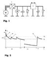
- FIG. 1 the power supply network of a motor vehicle is shown schematically.
- the electrical energy for this power supply network is provided by a generator 1 (“alternator”) in the form of AC voltage, which is converted into DC voltage in a rectifier 2.
- This DC voltage is fed to a starter motor 3 for starting the internal combustion engine (not shown) of the motor vehicle, a supercapacitor 4, possibly further consumers 5, and a control unit 6 with bidirectional power electronics.
- the power electronics can be a direct voltage converter (DC / DC converter), pulse width modulation, a relay or the like.
- the DC voltage is passed on to an electrochemical rechargeable battery 7 and to further consumers 8 via the control unit 6.
- the consumers 5 connected to the supercapacitor 4 are preferably those with a high dynamic range and a high maximum load (i.e. a large ratio of peak power to average power).
- examples of this include an electrically assisted steering system, electric brakes or an electrically assisted turbocharger.
- the battery 7 preferably supplies consumers 8 with less dynamics and power consumption.
- the supercapacitor 4 on the other hand, has a very long service life, high cycle capability and low costs due to the production from inexpensive materials. For this reason, the supercapacitor 4 has a much lower "price" per unit of energy passed through, so that it is used advantageously for dynamic consumers with high load absorption.
- the power supply network shown in FIG. 1 is not only optimized in terms of its architecture, but the control unit 6 is also set up for optimal operation in the standby mode.
- a standby mode is present in particular when the internal combustion engine of the motor vehicle is switched off and the generator 1 therefore does not generate any energy. In this case, it must be ensured that when the motor vehicle is started again, sufficient electrical energy is available for the consumers then taking action, in particular the starter motor 3.
- the control unit 6 ensures this by a method in which energy is shifted between the supercapacitor 4 and the battery 7 as required, as will be explained below with reference to FIG. 2.
- FIG. 2 shows the output voltage U of the supercapacitor 4 in the course of the time t after the internal combustion engine has been switched off.
- the voltage which is initially at a high voltage level U 0 , is slowly reduced along curve 10 by self-discharge, by loads still applied when the motor is switched off, by supercapacitor compensation circuits or the like. If the voltage thereby reaches a minimum value U l , the control unit 6 increases it again along the curve 11 by an energy transfer from the battery 7 to the supercapacitor 4 up to a maximum value U h . This process is repeated as often as required in the short-term standby mode ST. The voltage of the supercapacitor is kept in this way by the control unit 6 in the short-term standby mode ST within a relatively narrow voltage window ⁇ U between U l and U h .
- the control unit 6 In order to be able to carry out the described function, the control unit 6 must continuously monitor the voltage of the supercapacitor 4. Since the voltage represents a direct measure of the energy content of the supercapacitor 4, a strategy of this type can ensure that a minimal energy supply is constantly maintained in the supercapacitor 4 during the short-term standby mode ST. In any case, this is the case as long as the battery 7 contains sufficient energy for the continued refreshing of the supercapacitor 4.
- the refreshing of the capacitor voltage U is terminated at the maximum value U h , since the life expectancy of the capacitor 4 decreases as the capacitor voltage increases.
- the corresponding relationship is shown in FIG. 3 in a diagram which shows the capacitor voltage U in volts on the horizontal axis and the associated life expectancy t L in years on the vertical axis. Furthermore, various curves running parallel to one another are shown, which reflect the decrease in life expectancy with increasing temperature T of the supercapacitor. Maintaining the voltage of the supercapacitor 4 in the voltage window ⁇ U described therefore ensures that the capacitor is protected and, at the same time, the motor vehicle can be restarted at any time with the help of energy from the supercapacitor 4 in the short-term standby mode ST.
- the short-term standby mode ST goes into a long-term standby mode LT about.
- the duration mentioned can range from a few minutes to a few months.
- the supercapacitor 4 in the long-term standby mode LT the supercapacitor 4 can be discharged as far as desired, in particular also completely.
- the capacitor voltage U up to the maximum voltage U h is only refreshed if a corresponding activation signal is sent to the control unit 6 at a time t A.
- the activation signal can be generated by a clock generator at regular time intervals. However, it is preferably an external activation signal that is triggered remotely by the user or that is generated, for example, during an activity such as opening the doors. Opening the doors is an indication that the motor vehicle is about to be restarted.
- the power supply network is optimally prepared for restarting in these cases.
- the control unit 6 can furthermore be designed to transmit excess energy of the supercapacitor 4 into the battery 7 at the beginning of a standby mode. This is the case in FIG. 2 for the energy 9 shown hatched, which arises from the reduction of the original capacitor voltage U 0 to the maximum value U h . Similarly, at the beginning of the long-term standby mode LT, partial or complete energy transfer from the supercapacitor 4 to the battery 7 can take place (not shown).
- This energy of the supercapacitor can be used to charge the battery 7 over a long period of time at low currents in order to achieve a high SOC (state of charge) of the battery (lead acid batteries require a charging process with low currents for 6 to 24 h depending on the SOC to achieve a 100% SOC).
- control method implemented in the control unit 6 can contain an algorithm which consumers, who consume electricity even after the internal combustion engine has been switched off, during an initial phase the super capacitor 4 and later (if a minimum voltage of the super capacitor 4 is undershot) supplied from the battery 7.
Landscapes
- Engineering & Computer Science (AREA)
- Power Engineering (AREA)
- Mechanical Engineering (AREA)
- Charge And Discharge Circuits For Batteries Or The Like (AREA)
- Electric Propulsion And Braking For Vehicles (AREA)
- Supply And Distribution Of Alternating Current (AREA)
- Hybrid Cells (AREA)
- Direct Current Feeding And Distribution (AREA)
- Power-Operated Mechanisms For Wings (AREA)
Abstract
Description
- Die Erfindung betrifft ein Verfahren zur Spannungsregelung im Stromversorgungsnetz eines Kraftfahrzeuges, welches einen Superkondensator enthält, sowie ein zur Durchführung dieses Verfahrens eingerichtetes Stromversorgungsnetz.
- Mit Hilfe neuer Technologien ist die Herstellung von sogenannten Superkondensatoren möglich geworden, die sich von herkömmlichen Kondensatoren durch eine hohe Leistungsdichte von typischerweise 1-3 kWh/kg, eine hohe Zyklusfähigkeit und eine hohe mechanischen Robustheit unterscheiden. Dies eröffnet zahlreiche Einsatzmöglichkeiten im Bereich der Kraftfahrzeugtechnik, wobei derartige Superkondensatoren sogar als Kurzzeitspeicher für Elektrofahrzeuge eingesetzt werden können.
- Nachteilig an Superkondensatoren ist im Vergleich zu elektrochemischen Energiespeichern ihr verhältnismäßig geringer Energiegehalt, welcher stark von der Ausgangsspannung des Superkondensators abhängt. Bei Betrieb in einem Bereitschaftsmodus ("Stand-by Betrieb") findet zudem durch eine Selbstentladung, durch Verbraucher bei abgeschaltetem Kraftfahrzeugmotor oder durch Superkondensator-Ausgleichsschaltkreise eine langsame Entladung von Superkondensatoren statt. Wenn die Ausgangsspannung unter eine bestimmte Grenze abfällt, kann hierdurch die Leistungsfähigkeit und das Verhalten des Superkondensators im Bereitschaftsmodus erheblich beeinträchtigt, oder der Kondensator kann ganz ausfallen.
- Vor diesem Hintergrund war es Aufgabe der vorliegenden Erfindung, eine Spannungsregelung im Stromversorgungsnetz eines Kraftfahrzeuges mit einem Superkondensator bereitzustellen, welche eine hohe Lebensdauer des Superkondensators und eine sichere Funktionalität im Bereitschaftsmodus gewährleistet.
- Diese Aufgabe wird durch ein Verfahren mit den Merkmalen des Anspruchs 1 sowie durch ein Stromversorgungsnetz mit den Merkmalen des Anspruchs 9 gelöst.
- Vorteilhafte Ausgestaltungen sind in den Unteransprüchen enthalten.
- Das erfindungsgemäße Verfahren zur Spannungsregelung im Stromversorgungsnetz eines Kraftfahrzeuges, welches einen Superkondensator enthält, ist dadurch gekennzeichnet, daß in einem Kurzzeit-Bereitschaftsmodus der Energievorrat des Superkondensators bei Bedarf aufgefrischt wird, um einen minimalen Energievorrat im Superkondensator aufrecht zu erhalten. Die Bezeichnung "Kurzzeit" - Bereitschaftsmodus dient diesbezüglich dazu, diesen Modus von einem später noch zu erläuternden zweiten Bereitschaftsmodus unterscheidbar zu machen.
- Der Bereitschaftsmodus des Superkondensators liegt in der Regel bei Stillstand des Kraftfahrzeuges und abgeschalteter Brennkraftmaschine vor. Durch das gelegentliche Auffrischen des Energievorrates des Superkondensators wird in einem solchen Bereitschaftsmodus ein minimaler Energiegehalt des Superkondensators sichergestellt, so daß dieser bei Bedarf, zum Beispiel bei einem erneuten Anlassen des Kraftfahrzeuges, den angeschlossenen Verbrauchern in ausreichendem Maße elektrische Energie zur Verfügung stellen kann. Verbraucher mit einem stark variierenden, unter Umständen sehr hohen Leistungsbedarf - wie zum Beispiel der Startermotor - können auf diese Weise zu jedem Zeitpunkt ausreichend vom Superkondensator versorgt werden. Die üblicherweise vorhandene Batterie des Stromversorgungsnetzes, deren Lebenszeit durch hohe dynamische Lasten stark verkürzt wird, kann dadurch geschont werden.
- Gemäß einer bevorzugten Ausgestaltung des Verfahrens erfolgt das Auffrischen des Energievorrates des Superkondensators im Kurzzeit-Bereitschaftsmodus immer dann, wenn die Spannung des Superkondensators unter einen Minimalwert sinkt. Dieses Vorgehen nutzt die Tatsache aus, daß der Energievorrat in einem Superkondensator gesetzmäßig mit dessen Ausgangsspannung zusammenhängt. Eine verhältnismäßig einfach durchzuführende Überwachung der Spannung reicht daher aus, um die Zeitpunkte festzustellen, zu denen ein Auffrischen des Superkondensators erforderlich ist.
- Wie bereits erwähnt, kann das Verfahren durch die Einführung eines weiteren, sogenannten "Langzeit" - Bereitschaftsmodus weitergebildet werden. Im Langzeit - Bereitschaftsmodus erfolgt ein Auffrischen des Energievorrates des Superkondensators (nur) in Reaktion auf ein Aktivierungssignal, wobei durch das Auffrischen ein minimaler Energievorrat im Superkondensator hergestellt wird. Die Größe dieses minimalen Energievorrates ist vorzugsweise dieselbe wie beim Kurzzeit-Bereitschaftsmodus. Anders als bei Letzterem besteht das Ziel jedoch nicht darin, den minimalen Energievorrat durchgehend aufrecht zu erhalten, sondern die im Superkondensator gespeicherte Energie kann vor dem Aktivierungssignal deutlich geringer, gegebenenfalls sogar Null sein. Der Langzeit-Bereitschaftsmodus ist daher insbesondere dazu geeignet, bei einem länger andauernden Stillstand des Kraftfahrzeuges eine hohe Lebensdauer des Superkondensators, welche mit dessen Entladung steigt, sicherzustellen und gleichzeitig eine schnelle Inbetriebnahme des Kraftfahrzeuges zu gewährleisten.
- Gemäß einer bevorzugten Ausgestaltung des vorstehend erläuterten Verfahrens kann das Aktivierungssignal zeitlich periodisch, d.h. jeweils nach einer fest vorgegebenen Zeitdauer, ausgelöst werden. Zusätzlich oder alternativ kann das Aktivierungssignal auch nach Detektion eines vorgegebenen Ereignisses ausgelöst werden. Ein solches Ereignis kann insbesondere das Öffnen einer Tür des Kraftfahrzeuges sein, welches in der Regel ein Anzeichen für eine bevorstehende Inbetriebnahme des Kraftfahrzeuges ist. Ferner kann das Aktivierungssignal z. B. auch durch das Öffnen eines Garagentores oder das Einstecken des Zündschlüssels in das Zündschloss ausgelöst werden. Mit Hilfe der genannten Signale ist es möglich, auch bei einer längeren Auszeit des Kraftfahrzeuges eine verhältnismäßig schnelle erneute Inbetriebnahme unter Rückgriff auf den Superkondensator zu ermöglichen.
- Entsprechend einer bevorzugten Ausgestaltung des Verfahrens wird ein Auffrisch-Vorgang des Energievorrates des Superkondensators im Kurzzeit-Bereitschaftsmodus und/oder im Langzeit-Bereitschaftsmodus beendet, wenn die Spannung des Superkondensators einen vorgegebenen Maximalwert überschreitet. Dieser Maximalwert wird in Abhängigkeit vom Typ des Superkondensators vorzugsweise derart festgelegt, daß der damit verbundene Energiegehalt des Superkondensators einerseits für die gewünschten Funktionen des Kraftfahrzeuges ausreichend ist und daß dieser andererseits unterhalb der maximal erlaubten Spannung für den Superkondensator liegt, um dessen Lebensdauer nicht zu sehr zu verkürzen. Der vorgegebene Maximalwert stellt somit einen Kompromiss zwischen Funktionsbereitschaft des Kraftfahrzeuges und Schonung des Superkondensators dar.
- Das Stromversorgungsnetz des Kraftfahrzeuges enthält typischerweise noch eine (wiederaufladbare) Batterie, in welcher eine größere Energiemenge für einen längeren Zeitraum gespeichert werden kann. Bei einem solchen Stromversorgungsnetz erfolgt das Auffrischen des Energievorrates des Superkondensators vorzugsweise durch einen Energietransfer von der Batterie zum Superkondensator.
- Weiterhin kann zu Beginn des Kurzzeit-Bereitschaftsmodus und/oder des Langzeit-Bereitschaftsmodus der Superkondensator bis zu einer vorgegebenen Entladespannung entladen werden, wobei die Entladespannung vorzugsweise denselben Wert wie die oben bereits erwähnte Maximalspannung der Auffrischvorgänge haben kann. Das Entladen des Superkondensators dient dazu, durch einen Spannungsabbau die Lebensdauer des Kondensators zu erhöhen. Die dem Superkondensator entnommene Energie wird dabei vorteilhafterweise in eine Batterie des Stromversorgungsnetzes übertragen, so daß diese nicht verloren geht.
- Gemäß einer optionalen Variante des Verfahrens geht der Kurzzeit-Bereitschaftsmodus eine vorgegebene Zeitdauer nach seinem Beginn in den Langzeit-Bereitschaftsmodus über. Die genannte Zeitdauer kann dabei je nach den zugrunde gelegten Zielvorgaben in einem weiten Bereich von typischerweise zwischen einer Minute und zwei Monaten festgelegt werden. Besonders bevorzugt ist es, die Zeitdauer des Kurzzeit-Bereitschaftsmodus auf ca. 24 Stunden festzulegen, da viele Benutzungshandlungen eines Kraftfahrzeuges im Tagesrhythmus erfolgen. Wenn daher nach Ablauf von 24 Stunden keine erneute Inbetriebnahme des Kraftfahrzeuges erfolgt ist, ist ein länger fortgesetzter Stillstand des Kraftfahrzeuges wahrscheinlich, so daß zur besseren Schonung des Superkondensators der Langzeit-Bereitschaftsmodus bevorzugt wird.
- Die Erfindung betrifft ferner ein Stromversorgungsnetz für ein Kraftfahrzeug mit einem Superkondensator, welches durch eine mit dem Superkondensator gekoppelte Kontrolleinheit gekennzeichnet ist, die zur Durchführung eines Verfahrens der vorstehend erläuterten Art eingerichtet ist. D.h., daß die Kontrolleinheit insbesondere dahingehend ausgebildet ist, in einem Kurzzeit-Bereitschaftsmodus einen minimalen Energievorrat in dem Superkondensator aufrecht zu erhalten. Dies kann insbesondere durch Überwachung der Spannung des Superkondensators geschehen, wobei Energie aus einer Batterie in den Superkondensator übertragen wird, wenn dessen Spannung einen Minimalwert unterschreitet. Weiterhin kann die Kontrolleinheit zur Realisierung eines Langzeit-Bereitschaftsmodus eingerichtet sein, in welchem nur auf ein Aktivierungssignal hin ein Auffrischen des Energievorrates im Superkondensator erfolgt. Der Auffrischvorgang endet dabei vorzugsweise bei einem Maximalwert der Spannung des Superkondensators, um dessen Lebenserwartung nicht zu beeinträchtigen.
- In dem beschriebenen Stromversorgungsnetz sind vorzugsweise Verbraucher mit einem hohen dynamischen Lastaufkommen an den Superkondensator angeschlossen. Im Gegensatz zu einer Batterie ist der Superkondensator nämlich hervorragend zur Bewältigung solcher Lasten geeignet. Beispiele für derartige Verbraucher sind der Startermotor, ein elektronisch unterstütztes Lenksystem (EPAS: Electric Power Assisted Steering), elektrisch unterstützte Bremsen und ein elektrisch unterstützter Turbolader.
- Im Folgenden wird die Erfindung anhand der Figuren beispielhaft näher erläutert.
Es zeigen: - Fig. 1
- die Komponenten eines erfindungsgemäßen Stromversorgungsnetzes mit einem Superkondensator;
- Fig. 2
- den Spannungsverlauf am Superkondensator während eines erfindungsgemäßen Kurzzeit- und eines Langzeit-Bereitschaftsmodus, und
- Fig. 3
- die Lebenserwartung eines Superkondensators in Abhängigkeit von dessen Spannung und seiner Temperatur.
- In Figur 1 ist das Stromversorgungsnetz eines Kraftfahrzeuges schematisch dargestellt. Die elektrische Energie für dieses Stromversorgungsnetz wird von einem Generator 1 ("Lichtmaschine") in Form von Wechselspannung bereitgestellt, welche in einem Gleichrichter 2 in Gleichspannung umgewandelt wird. Diese Gleichspannung wird einem Startermotor 3 zum Anlassen der Brennkraftmaschine (nicht dargestellt) des Kraftfahrzeuges, einem Superkondensator 4, ggf. weiteren Verbrauchern 5, und einer Kontrolleinheit 6 mit einer bidirektionalen Leistungselektronik zugeführt. Die Leistungselektronik kann dabei ein Gleichspannungswandler (DC/DC-Konverter), eine Pulsweitenmodulation, ein Relais oder dergleichen sein. Über die Kontrolleinheit 6 wird die Gleichspannung an eine elektrochemische wiederaufladbare Batterie 7 sowie an weitere Verbraucher 8 weitergeleitet.
- Die an den Superkondensator 4 angeschlossenen Verbraucher 5 sind vorzugsweise solche mit einer hohen Dynamik und einer hohen Maximallast (d.h. einem großen Verhältnis von Spitzenleistung zu Durchschnittsleistung). Beispiele hierfür sind neben dem Startermotor 3 ein elektrisch unterstütztes Lenksystem, elektrische Bremsen oder ein elektrisch unterstützter Turbolader. Die Batterie 7 versorgt dagegen vorzugsweise Verbraucher 8 mit einer geringeren Dynamik und Leistungsaufnahme.
- Die beschriebene Verteilung der Verbraucher 3, 5 und 8 auf den Superkondensator 4 beziehungsweise die Batterie 7 wirkt sich vorteilhaft auf die Lebenserwartung der Batterie 7 aus. Die meisten elektrochemischen Energiespeichereinrichtungen haben nämlich eine begrenzte Lebensdauer, die durch den Energiedurchsatz bestimmt wird. Dieser maximale Energiedurchsatz hängt nicht nur hochgradig von der Amplitude des Ladungsstromes ab, sondern führt auch dazu, daß eine Ladungsübertragung durch eine solche Vorrichtung einen gewissen "Preis" hat. Es ist daher vorteilhaft, die Spitzenladungs- und Entladungsströme und den Energiedurchsatz der Batterie 7 zu minimieren, um die Kosten des Systems (kleinere Batterie) zu reduzieren und die Lebensdauer dieser Vorrichtung zu maximieren. Dies geschieht durch die Optimierung und Verwendung der Batterie 7 für Lasten geringer Leistungsaufnahme während langer Zeitdauern.
- Der Superkondensator 4 hat dagegen eine sehr lange Lebensdauer, eine hohe Zyklusfähigkeit und geringe Kosten durch Herstellung aus kostengünstigen Materialien. Aus diesem Grunde hat der Superkondensator 4 einen sehr viel geringeren "Preis" pro Einheit durchgesetzter Energie, so daß er vorteilhaft für dynamische Verbraucher mit hoher Lastaufnahme eingesetzt wird.
- Das in Figur 1 dargestellte Stromversorgungsnetz ist jedoch nicht nur hinsichtlich seiner Architektur optimiert, sondern die Kontrolleinheit 6 ist darüber hinaus für einen optimalen Betrieb im Bereitschaftsmodus eingerichtet. Ein Bereitschaftsmodus liegt insbesondere dann vor, wenn die Brennkraftmaschine des Kraftfahrzeuges abgestellt ist und der Generator 1 daher keine Energie erzeugt. In diesem Fall muss sichergestellt werden, daß bei einem erneuten Starten des Kraftfahrzeuges ausreichend elektrische Energie für die dann in Aktion tretenden Verbraucher wie vor allem den Startermotor 3 zur Verfügung steht. Die Kontrolleinheit 6 gewährleistet dies durch ein Verfahren, bei welchem Energie zwischen dem Superkondensator 4 und der Batterie 7 nach Bedarf verschoben wird, wie nachfolgend anhand von Figur 2 erläutert wird.
- Figur 2 zeigt die Ausgangsspannung U des Superkondensators 4 im Verlauf über der Zeit t nach dem Ausschalten der Brennkraftmaschine. Die zunächst auf einem hohen Spannungsniveau U0 liegende Spannung wird durch eine Selbstentladung, durch bei abgeschaltetem Motor noch anliegende Lasten, durch Superkondensator-Ausgleichschaltkreise od. dgl. langsam entlang der Kurve 10 abgebaut. Wenn die Spannung dabei einen Minimalwert Ul erreicht, wird diese von der Kontrolleinheit 6 entlang der Kurve 11 durch einen Energietransfer von der Batterie 7 zum Superkondensator 4 wieder bis zu einem Maximalwert Uh erhöht. Dieser Vorgang wiederholt sich im Kurzzeit-Bereitschaftsmodus ST so oft wie erforderlich. Die Spannung des Superkondensators wird auf diese Weise von der Kontrolleinheit 6 im Kurzzeit-Bereitschaftsmodus ST innerhalb eines verhältnismäßig engen Spannungsfensters ΔU zwischen Ul und Uh gehalten.
- Um die beschriebene Funktion ausführen zu können, muss die Kontrolleinheit 6 die Spannung des Superkondensators 4 fortlaufend überwachen. Da die Spannung ein direktes Maß für den Energiegehalt des Superkondensators 4 darstellt, kann durch eine derartige Strategie sichergestellt werden, daß während des Kurzzeit-Bereitschaftsmodus ST ständig ein minimaler Energievorrat im Superkondensator 4 aufrecht erhalten wird. Dies ist jedenfalls so lange der Fall, wie die Batterie 7 ausreichend Energie für das fortgesetzte Auffrischen des Superkondensators 4 enthält.
- Das Auffrischen der Kondensatorspannung U wird bei dem Maximalwert Uh beendet, da die Lebenserwartung des Kondensators 4 mit zunehmender Kondensatorspannung sinkt. Der entsprechende Zusammenhang ist in Figur 3 in einem Diagramm dargestellt, welches auf der horizontalen Achse die Kondensatorspannung U in Volt und auf der vertikalen Achse die zugehörige Lebenserwartung tL in Jahren zeigt. Ferner sind verschiedene, parallel zueinander verlaufende Kurven dargestellt, die das Abnehmen der Lebenserwartung mit zunehmender Temperatur T des Superkondensators widerspiegeln. Durch das Halten der Spannung des Superkondensators 4 in dem beschriebenen Spannungsfenster ΔU wird daher gewährleistet, daß der Kondensator geschont wird und gleichzeitig das Kraftfahrzeug im Kurzzeit-Bereitschaftsmodus ST jederzeit mit Hilfe von Energie aus dem Superkondensator 4 wieder gestartet werden kann.
- Wird das Kraftfahrzeug allerdings für eine längere Zeitdauer nicht neu gestartet, so geht der Kurzzeit-Bereitschaftsmodus ST in einen Langzeit-Bereitschaftsmodus LT über. Die genannte Zeitdauer kann dabei im Bereich von einigen Minuten bis einigen Monaten liegen.
- Wie aus Figur 2 zu erkennen ist, kann sich im Langzeit-Bereitschaftsmodus LT der Superkondensator 4 beliebig weit, insbesondere auch vollständig entladen. Ein Auffrischen der Kondensatorspannung U bis zur Maximalspannung Uh erfolgt nur, wenn ein entsprechendes Aktivierungssignal zu einem Zeitpunkt tA an die Kontrolleinheit 6 gegeben wird. Das Aktivierungssignal kann im einfachsten Falle von einem Taktgenerator in regelmäßigen Zeitabständen erzeugt werden. Vorzugsweise handelt es sich jedoch um ein externes Aktivierungssignal, das vom Benutzer fernausgelöst wird oder das zum Beispiel bei einer Tätigkeit wie dem Öffnen der Türen erzeugt wird. Ein Öffnen der Türen ist dabei ein Indiz dafür, daß eine erneute Inbetriebnahme des Kraftfahrzeuges bevorsteht. Durch das Auffrischen der Ladung des Superkondensators 4 ist das Stromversorgungsnetz in diesen Fällen optimal auf das erneute Starten vorbereitet.
- Die Kontrolleinheit 6 kann weiterhin dahingehend ausgebildet sein, zu Beginn eines Bereitschaftsmodus überschüssige Energie des Superkondensators 4 in die Batterie 7 zu übertragen. Dies ist bei Figur 2 für die schraffiert dargestellte Energie 9 der Fall, welche durch den Abbau der ursprünglichen Kondensatorspannung U0 auf den Maximalwert Uh anfällt. In ähnlicher Weise kann zu Beginn des Langzeit-Bereitschaftsmodus LT ein teilweiser oder vollständiger Energieübertrag aus dem Superkondensator 4 zur Batterie 7 erfolgen (nicht dargestellt). Diese Energie des Superkondensators kann zum Laden der Batterie 7 über eine lange Zeitdauer bei geringen Strömen verwendet werden, um einen hohen SOC (State of Charge: Ladezustand) der Batterie zu erreichen (Bleisäure-Batterien benötigen einen Ladevorgang mit geringen Strömen für 6 bis 24 h je nach SOC, um ein 100% SOC zu erreichen).
- Weiterhin kann das in der Kontrolleinheit 6 implementierte Regelungsverfahren einen Algorithmus enthalten, welcher Verbraucher, die auch nach Abschalten der Brennkraftmaschine Strom verbrauchen, während einer anfänglichen Phase aus dem Superkondensator 4 und später (wenn eine minimale Spannung des Superkondensators 4 unterschritten wird) aus der Batterie 7 versorgt.
Claims (10)
- Verfahren zur Spannungsregelung im Stromversorgungsnetz eines Kraftfahrzeugs, welches einen Superkondensator (4) enthält,
dadurch gekennzeichnet, daß
in einem Kurzzeit-Bereitschaftsmodus (ST) der Energievorrat des Superkondensators bei Bedarf aufgefrischt wird, um einen minimalen Energievorrat im Superkondensator aufrecht zu erhalten. - Verfahren nach Anspruch 1,
dadurch gekennzeichnet, daß
der Energievorrat des Superkondensators (4) im Kurzzeit-Bereitschaftsmodus (ST) aufgefrischt wird, wenn die Spannung des Superkondensators unter einen vorgegebenen Minimalwert (Ul) gesunken ist. - Verfahren nach Anspruch 1 oder 2,
dadurch gekennzeichnet, daß
in einem Langzeit-Bereitschaftsmodus (LT) der Energievorrat des Superkondensators (4) in Reaktion auf ein Aktivierungssignal aufgefrischt wird, um einen minimalen Energievorrat im Superkondensator (4) herzustellen. - Verfahren nach Anspruch 3,
dadurch gekennzeichnet, daß
das Aktivierungssignal zeitlich periodisch und/oder nach Detektion eines vorgegebenen Ereignisses, insbesondere des Öffnens einer Tür des Kraftfahrzeuges, ausgelöst wird. - Verfahren nach mindestens einem der Ansprüche 1 bis 4,
dadurch gekennzeichnet, daß
ein Auffrisch-Vorgang des Energievorrats im Kurzzeit-Bereitschaftsmodus (ST) und/oder im Langzeit-Bereitschaftsmodus (LT) beendet wird, wenn die Spannung des Superkondensators (4) einen vorgegebenen Maximalwert (Uh) überschreitet. - Verfahren nach mindestens einem der Ansprüche 1 bis 5,
dadurch gekennzeichnet, daß
der Energievorrat des Superkondensators (4) durch Energietransfer aus einer Batterie (7) des Stromversorgungsnetzes aufgefrischt wird. - Verfahren nach mindestens einem der Ansprüche 1 bis 6,
dadurch gekennzeichnet, daß
zu Beginn des Kurzzeit-Bereitschaftsmodus (ST) und/oder des Langzeit-Bereitschaftsmodus (LT) der Superkondensator (4) bis zu einer vorgegebenen Entladespannung (Uh) entladen wird, wobei die dabei entnommene Energie vorzugsweise in eine Batterie (7) des Stromversorgungsnetzes transferiert wird. - Verfahren nach mindestens einem der Ansprüche 3 bis 7,
dadurch gekennzeichnet, daß
der Kurzzeit-Bereitschaftsmodus (ST) vorzugsweise nach einem Zeitraum von einer Minute bis zwei Monaten, besonders bevorzugt nach ca. 24 Stunden, in den Langzeit-Bereitschaftsmodus (LT) übergeht. - Stromversorgungsnetz für ein Kraftfahrzeug mit einem Superkondensator (4), gekennzeichnet durch eine mit dem Superkondensator gekoppelte Kontrolleinheit (6), welche dahingehend ausgebildet ist, ein Verfahren nach mindestens einem der Ansprüche 1 bis 8 auszuführen.
- Stromversorgungsnetz nach Anspruch 9,
dadurch gekennzeichnet, daß
an den Superkondensator (4) Verbraucher (3, 5) mit einem hohen dynamischen Lastaufkommen angeschlossen sind.
Priority Applications (4)
| Application Number | Priority Date | Filing Date | Title |
|---|---|---|---|
| AT02102398T ATE350248T1 (de) | 2002-09-30 | 2002-09-30 | Verfahren zur stromversorgung in einem stromversorgungsnetz mit einem superkondensator |
| DE50209176T DE50209176D1 (de) | 2002-09-30 | 2002-09-30 | Verfahren zur Stromversorgung in einem Stromversorgungsnetz mit einem Superkondensator |
| EP02102398A EP1403143B1 (de) | 2002-09-30 | 2002-09-30 | Verfahren zur Stromversorgung in einem Stromversorgungsnetz mit einem Superkondensator |
| US10/674,935 US7038427B2 (en) | 2002-09-30 | 2003-09-30 | Method for supplying power in an electrical power supply system having a supercapacitor |
Applications Claiming Priority (1)
| Application Number | Priority Date | Filing Date | Title |
|---|---|---|---|
| EP02102398A EP1403143B1 (de) | 2002-09-30 | 2002-09-30 | Verfahren zur Stromversorgung in einem Stromversorgungsnetz mit einem Superkondensator |
Publications (2)
| Publication Number | Publication Date |
|---|---|
| EP1403143A1 true EP1403143A1 (de) | 2004-03-31 |
| EP1403143B1 EP1403143B1 (de) | 2007-01-03 |
Family
ID=31970454
Family Applications (1)
| Application Number | Title | Priority Date | Filing Date |
|---|---|---|---|
| EP02102398A Expired - Lifetime EP1403143B1 (de) | 2002-09-30 | 2002-09-30 | Verfahren zur Stromversorgung in einem Stromversorgungsnetz mit einem Superkondensator |
Country Status (4)
| Country | Link |
|---|---|
| US (1) | US7038427B2 (de) |
| EP (1) | EP1403143B1 (de) |
| AT (1) | ATE350248T1 (de) |
| DE (1) | DE50209176D1 (de) |
Cited By (10)
| Publication number | Priority date | Publication date | Assignee | Title |
|---|---|---|---|---|
| FR2907978A1 (fr) * | 2006-10-25 | 2008-05-02 | Peugeot Citroen Automobiles Sa | Procede d'initialisation d'un element de stockage d'energie. |
| FR2912268A1 (fr) * | 2007-02-01 | 2008-08-08 | Peugeot Citroen Automobiles Sa | Procede et systeme de surveillance de l'etat de charge et de conditionnement d'un organe de stockage d'energie electrique d'un vehicule |
| FR2912190A1 (fr) * | 2007-02-07 | 2008-08-08 | Peugeot Citroen Automobiles Sa | Procede de demarrage du moteur thermique d'un vehicule automobile hybride |
| WO2009024395A3 (de) * | 2007-08-21 | 2009-04-30 | Bosch Gmbh Robert | Vorrichtung und verfahren zur sicheren spannungsversorgung |
| FR2926168A1 (fr) * | 2008-01-09 | 2009-07-10 | Peugeot Citroen Automobiles Sa | Circuit electrique comportant un moyen de stockage commutable comportant des elements aptes a fournir une tension variable |
| WO2009115298A1 (de) * | 2008-03-17 | 2009-09-24 | Fraunhofer-Gesellschaft zur Förderung der angewandten Forschung e.V. | Vorrichtung und verfahren zum wandeln eines potentials |
| CN101161498B (zh) * | 2006-10-11 | 2012-05-23 | 现代自动车株式会社 | 混合燃料电池客车的电力系统及其控制方法 |
| FR2983435A1 (fr) * | 2011-12-05 | 2013-06-07 | Peugeot Citroen Automobiles Sa | Procede de gestion de l'energie electrique d'un vehicule automobile et vehicule automobile mettant en oeuvre un tel procede |
| EP3013617A4 (de) * | 2013-06-28 | 2017-11-08 | CAP-XX Limited | System zur steuerung eines kraftfahrzeugmotors und verfahren zur steuerung eines kraftfahrzeugmotors |
| DE102010000522B4 (de) | 2009-02-24 | 2022-03-24 | Denso Corporation | Elektrisches Leistungsversorgungssystem für Fahrzeuge |
Families Citing this family (15)
| Publication number | Priority date | Publication date | Assignee | Title |
|---|---|---|---|---|
| DE102004062939B4 (de) | 2004-12-28 | 2019-02-21 | Volkswagen Ag | Verfahren und Vorrichtung zum optimierten Starten eines Verbrennungsmotors |
| FR2911015B1 (fr) * | 2006-12-29 | 2009-05-01 | Peugeot Citroen Automobiles Sa | Procede de gestion des flux energetiques dans un dispositif d'alimentation electrique |
| TW200847580A (en) * | 2007-04-04 | 2008-12-01 | Cooper Technologies Co | System and method for boosting battery output |
| JP2009171694A (ja) * | 2008-01-15 | 2009-07-30 | Nisshinbo Holdings Inc | 充電装置 |
| TWI472120B (zh) * | 2008-07-23 | 2015-02-01 | 皇家飛利浦電子股份有限公司 | 用於對超級電容器充電之方法及充電器 |
| US8203310B2 (en) * | 2008-10-20 | 2012-06-19 | The Raymond Corporation | Energy storage module for load leveling in lift truck or other electrical vehicle |
| FR2942354B1 (fr) * | 2009-02-19 | 2013-05-10 | Peugeot Citroen Automobiles Sa | Procede de securisation du fonctionnement d'un dispositif de maintien en tension d'un vehicule |
| FR2949624B1 (fr) * | 2009-09-02 | 2017-07-28 | Valeo Equip Electr Moteur | Procede de charge d'un module auxiliaire de stockage d'energie |
| DE102011083286A1 (de) * | 2011-09-23 | 2013-03-28 | Robert Bosch Gmbh | Verfahren und Vorrichtung zum Versorgen eines Fahrzeugsystems eines Fahrzeugs mit Energie nach einem Energieversorgungsausfall im Fahrzeug |
| US9340114B2 (en) | 2012-01-23 | 2016-05-17 | Ford Global Technologies, Llc | Electric vehicle with transient current management for DC-DC converter |
| JP6137145B2 (ja) * | 2014-11-27 | 2017-05-31 | マツダ株式会社 | 車両用電源制御装置 |
| DE102015012358A1 (de) * | 2015-09-19 | 2017-03-23 | GM Global Technology Operations LLC (n. d. Ges. d. Staates Delaware) | Stromversorgungssystem eines Kraftfahrzeugs, Kraftfahrzeug sowie Verfahren zum Betrieb eines Stromversorgungssystems |
| US9816475B1 (en) * | 2016-05-11 | 2017-11-14 | Cooper Technologies Company | System and method for maximizing short-term energy storage in a supercapacitor array for engine start applications |
| GB2559106B (en) * | 2016-11-03 | 2020-01-01 | Jaguar Land Rover Ltd | Apparatus and method for hybrid energy storage |
| US12512692B1 (en) * | 2024-11-25 | 2025-12-30 | Shenzhen Leagend Optoelectronics Co., Ltd. | Supercapacitor control circuit and method for intelligently identifying starting mode of vehicle |
Citations (5)
| Publication number | Priority date | Publication date | Assignee | Title |
|---|---|---|---|---|
| EP0412631A2 (de) * | 1989-08-10 | 1991-02-13 | Isuzu Motors Limited | Stromversorgungseinrichtung für Kraftfahrzeug |
| FR2751145A1 (fr) * | 1996-07-09 | 1998-01-16 | Renault | Dispositif de controle de la charge d'un supercondensateur et procede de commande d'un tel dispositif |
| EP0865142A1 (de) * | 1997-03-13 | 1998-09-16 | Renault | Elektrische Versorgungseinrichtung mit Sekundärbatterie und Superkondensator |
| EP1013506A2 (de) * | 1998-12-21 | 2000-06-28 | Audi Ag | Bordnetz für ein Kraftfahrzeug |
| DE19915973C1 (de) * | 1999-04-09 | 2000-11-16 | Audi Ag | Verfahren zur Regelung der Bordnetzspannung eines Kraftfahrzeugs |
Family Cites Families (6)
| Publication number | Priority date | Publication date | Assignee | Title |
|---|---|---|---|---|
| EP0753925A3 (de) * | 1995-07-13 | 1997-07-02 | Renault | Vorrichtung zur Stromversorgung eines Kraftfahrzeuges und Verfahren zur Steuerung einer solchen Vorrichtung |
| GB9622307D0 (en) * | 1996-10-26 | 1996-12-18 | Lucas Ind Plc | Vehicle battery controller |
| US6271642B1 (en) * | 1998-02-13 | 2001-08-07 | Johnson Controls Technology Company | Advanced battery controller with state of charge control |
| DE19842656A1 (de) * | 1998-09-17 | 2000-03-23 | Volkswagen Ag | Zwei-Batteriensystem |
| GB2357641B (en) * | 1999-12-20 | 2002-02-20 | Motorola Ltd | DC-DC Converter and energy management system |
| DE10139608B4 (de) * | 2001-08-11 | 2007-05-16 | Nucellsys Gmbh | Brennstoffzellenanlage mit einem Gaserzeugungssystem und einem Brennstoffzellensystem und deren Verwendung |
-
2002
- 2002-09-30 EP EP02102398A patent/EP1403143B1/de not_active Expired - Lifetime
- 2002-09-30 DE DE50209176T patent/DE50209176D1/de not_active Expired - Lifetime
- 2002-09-30 AT AT02102398T patent/ATE350248T1/de not_active IP Right Cessation
-
2003
- 2003-09-30 US US10/674,935 patent/US7038427B2/en not_active Expired - Lifetime
Patent Citations (5)
| Publication number | Priority date | Publication date | Assignee | Title |
|---|---|---|---|---|
| EP0412631A2 (de) * | 1989-08-10 | 1991-02-13 | Isuzu Motors Limited | Stromversorgungseinrichtung für Kraftfahrzeug |
| FR2751145A1 (fr) * | 1996-07-09 | 1998-01-16 | Renault | Dispositif de controle de la charge d'un supercondensateur et procede de commande d'un tel dispositif |
| EP0865142A1 (de) * | 1997-03-13 | 1998-09-16 | Renault | Elektrische Versorgungseinrichtung mit Sekundärbatterie und Superkondensator |
| EP1013506A2 (de) * | 1998-12-21 | 2000-06-28 | Audi Ag | Bordnetz für ein Kraftfahrzeug |
| DE19915973C1 (de) * | 1999-04-09 | 2000-11-16 | Audi Ag | Verfahren zur Regelung der Bordnetzspannung eines Kraftfahrzeugs |
Cited By (17)
| Publication number | Priority date | Publication date | Assignee | Title |
|---|---|---|---|---|
| CN101161498B (zh) * | 2006-10-11 | 2012-05-23 | 现代自动车株式会社 | 混合燃料电池客车的电力系统及其控制方法 |
| WO2008050031A3 (fr) * | 2006-10-25 | 2008-07-17 | Peugeot Citroen Automobiles Sa | Procede d'initialisation d'un element de stockage d'energie |
| FR2907978A1 (fr) * | 2006-10-25 | 2008-05-02 | Peugeot Citroen Automobiles Sa | Procede d'initialisation d'un element de stockage d'energie. |
| FR2912268A1 (fr) * | 2007-02-01 | 2008-08-08 | Peugeot Citroen Automobiles Sa | Procede et systeme de surveillance de l'etat de charge et de conditionnement d'un organe de stockage d'energie electrique d'un vehicule |
| WO2008107616A3 (fr) * | 2007-02-01 | 2008-10-30 | Peugeot Citroen Automobiles Sa | Procede et systeme de surveillance de l'etat de charge et de conditionnement d'un organe de stockage d'energie electrique d'un vehicule |
| FR2912190A1 (fr) * | 2007-02-07 | 2008-08-08 | Peugeot Citroen Automobiles Sa | Procede de demarrage du moteur thermique d'un vehicule automobile hybride |
| WO2008110716A1 (fr) * | 2007-02-07 | 2008-09-18 | Peugeot Citroën Automobiles SA | Procede et systeme de demarrage du moteur thermique d ' un vehicule automobile hybride |
| WO2009024395A3 (de) * | 2007-08-21 | 2009-04-30 | Bosch Gmbh Robert | Vorrichtung und verfahren zur sicheren spannungsversorgung |
| EP2079148A3 (de) * | 2008-01-09 | 2014-04-30 | Peugeot Citroën Automobiles SA | Elektrischer Schaltkreis |
| FR2926168A1 (fr) * | 2008-01-09 | 2009-07-10 | Peugeot Citroen Automobiles Sa | Circuit electrique comportant un moyen de stockage commutable comportant des elements aptes a fournir une tension variable |
| WO2009115298A1 (de) * | 2008-03-17 | 2009-09-24 | Fraunhofer-Gesellschaft zur Förderung der angewandten Forschung e.V. | Vorrichtung und verfahren zum wandeln eines potentials |
| US8643346B2 (en) | 2008-03-17 | 2014-02-04 | Fraunhofer-Gesellschaft Zur Foerderung Der Angewandten Forschung E.V. | Device and method for converting a potential |
| DE102010000522B4 (de) | 2009-02-24 | 2022-03-24 | Denso Corporation | Elektrisches Leistungsversorgungssystem für Fahrzeuge |
| WO2013083916A1 (fr) * | 2011-12-05 | 2013-06-13 | Peugeot Citroen Automobiles Sa | Procede de gestion de l'energie electrique d'un vehicule automobile et vehicule automobile mettant en œuvre un tel procede |
| FR2983435A1 (fr) * | 2011-12-05 | 2013-06-07 | Peugeot Citroen Automobiles Sa | Procede de gestion de l'energie electrique d'un vehicule automobile et vehicule automobile mettant en oeuvre un tel procede |
| CN104093604A (zh) * | 2011-12-05 | 2014-10-08 | 标致·雪铁龙汽车公司 | 机动车辆的电能管理方法及实施该方法的机动车辆 |
| EP3013617A4 (de) * | 2013-06-28 | 2017-11-08 | CAP-XX Limited | System zur steuerung eines kraftfahrzeugmotors und verfahren zur steuerung eines kraftfahrzeugmotors |
Also Published As
| Publication number | Publication date |
|---|---|
| ATE350248T1 (de) | 2007-01-15 |
| US7038427B2 (en) | 2006-05-02 |
| EP1403143B1 (de) | 2007-01-03 |
| DE50209176D1 (de) | 2007-02-15 |
| US20040124811A1 (en) | 2004-07-01 |
Similar Documents
| Publication | Publication Date | Title |
|---|---|---|
| EP1403143B1 (de) | Verfahren zur Stromversorgung in einem Stromversorgungsnetz mit einem Superkondensator | |
| EP2047579B1 (de) | System zur spannungsversorgung von elektrischen verbrauchern eines kraftfahrzeugs unter verwendung eines supercaps | |
| EP2441162B1 (de) | Bordnetz für ein kraftfahrzeug und verfahren zum betreiben eines elektrischen verbrauchers | |
| EP2160813B1 (de) | Kraftfahrzeugbordnetz | |
| DE60221067T2 (de) | Kondensatorsystem für Kraftfahrzeug | |
| DE202013012133U1 (de) | Elektrische Speichereinrichtung | |
| DE102010025198A1 (de) | Kraftfahrzeug-Bordnetz und Verfahren zum Betreiben eines Kraftfahrzeug-Bordnetzes | |
| DE202005009886U1 (de) | Heizgerät für elektrische Speichervorrichtungen für Fahrzeuge | |
| DE102008054885A1 (de) | Vorrichtung und Verfahren zum Steuern einer Energieversorgung eines Bordnetzes eines Fahrzeugs | |
| EP1128187A2 (de) | Verfahren zur Ermittlung des Ladezustandes von Bleiakkumulatoren | |
| EP2777130A2 (de) | Verfahren zur bereitstellung von regelleistung in einem energieversorgungsnetz | |
| EP2386135A1 (de) | Bordnetz für ein fahrzeug mit start-stopp-system | |
| DE102014221482A1 (de) | Verfahren zur Ansteuerung einer Spannungsquelle zum Laden einer Batterie eines Kraftfahrzeugs | |
| EP1676738A2 (de) | Verfahren und Vorrichtung zum Betreiben eines Hybridenergiespeichers in einem Fahrzeug mit einem Hybridantriebsystem | |
| DE102012204976A1 (de) | Fahrzeug mit einer Bordnetzarchitektur und Verfahren zum Betreiben derselben | |
| EP0964996A1 (de) | Starthilfsanlage für einen dieselmotor sowie verfahren zum starten eines dieselmotors | |
| DE102022117000A1 (de) | Batterielademanager | |
| DE102009058362A1 (de) | Batteriesystem für ein Kraftfahrzeug, Verfahren zum Betrieb eines Batteriesystems eines Kraftfahrzeuges und Kraftfahrzeug | |
| EP2777119A2 (de) | Verfahren zur bereitstellung von regelleistung mit einem energieerzeuger und einem energieverbraucher | |
| EP1044852A2 (de) | Bordnetz für Kraftfahrzeuge | |
| DE102020130765A1 (de) | Verfahren und Vorrichtung zur Formierung | |
| WO2025061225A1 (de) | Verfahren zum ladezielspannungsgeregelten laden einer energiespeichervorrichtung mit einer mehrzahl von zellen für ein elektrisch antreibbares kraftfahrzeug, computerprogramm und/oder computerlesbares medium, datenverarbeitungsvorrichtung, kraftfahrzeug | |
| DE102010021402A1 (de) | Bordnetz für ein Kraftfahrzeug, Kraftfahrzeug und Verfahren zum Betreiben eines elektrischen Verbrauchers | |
| DE102006051588A1 (de) | Schaltungsanordnung zur Steuerung der Versorgung elektrischer Energieverbraucher und Verfahren zum Unterspannungsschutz eines Bordnetzes | |
| WO2019120735A1 (de) | Verfahren und vorrichtung zur bereitstellung der startfähigkeit eines kraftfahrzeugs |
Legal Events
| Date | Code | Title | Description |
|---|---|---|---|
| PUAI | Public reference made under article 153(3) epc to a published international application that has entered the european phase |
Free format text: ORIGINAL CODE: 0009012 |
|
| AK | Designated contracting states |
Kind code of ref document: A1 Designated state(s): AT BE BG CH CY CZ DE DK EE ES FI FR GB GR IE IT LI LU MC NL PT SE SK TR |
|
| AX | Request for extension of the european patent |
Extension state: AL LT LV MK RO SI |
|
| 17P | Request for examination filed |
Effective date: 20040930 |
|
| AKX | Designation fees paid |
Designated state(s): AT BE BG CH CY CZ DE DK EE ES FI FR GB GR IE IT LI LU MC NL PT SE SK TR |
|
| 17Q | First examination report despatched |
Effective date: 20050519 |
|
| RAP1 | Party data changed (applicant data changed or rights of an application transferred) |
Owner name: FORD GLOBAL TECHNOLOGIES, LLC |
|
| RAP1 | Party data changed (applicant data changed or rights of an application transferred) |
Owner name: FORD GLOBAL TECHNOLOGIES, LLC. |
|
| GRAP | Despatch of communication of intention to grant a patent |
Free format text: ORIGINAL CODE: EPIDOSNIGR1 |
|
| GRAS | Grant fee paid |
Free format text: ORIGINAL CODE: EPIDOSNIGR3 |
|
| GRAA | (expected) grant |
Free format text: ORIGINAL CODE: 0009210 |
|
| AK | Designated contracting states |
Kind code of ref document: B1 Designated state(s): AT BE BG CH CY CZ DE DK EE ES FI FR GB GR IE IT LI LU MC NL PT SE SK TR |
|
| PG25 | Lapsed in a contracting state [announced via postgrant information from national office to epo] |
Ref country code: IE Free format text: LAPSE BECAUSE OF FAILURE TO SUBMIT A TRANSLATION OF THE DESCRIPTION OR TO PAY THE FEE WITHIN THE PRESCRIBED TIME-LIMIT Effective date: 20070103 Ref country code: DK Free format text: LAPSE BECAUSE OF FAILURE TO SUBMIT A TRANSLATION OF THE DESCRIPTION OR TO PAY THE FEE WITHIN THE PRESCRIBED TIME-LIMIT Effective date: 20070103 Ref country code: FI Free format text: LAPSE BECAUSE OF FAILURE TO SUBMIT A TRANSLATION OF THE DESCRIPTION OR TO PAY THE FEE WITHIN THE PRESCRIBED TIME-LIMIT Effective date: 20070103 Ref country code: NL Free format text: LAPSE BECAUSE OF FAILURE TO SUBMIT A TRANSLATION OF THE DESCRIPTION OR TO PAY THE FEE WITHIN THE PRESCRIBED TIME-LIMIT Effective date: 20070103 |
|
| REG | Reference to a national code |
Ref country code: GB Ref legal event code: FG4D Free format text: NOT ENGLISH |
|
| REF | Corresponds to: |
Ref document number: 50209176 Country of ref document: DE Date of ref document: 20070215 Kind code of ref document: P |
|
| REG | Reference to a national code |
Ref country code: IE Ref legal event code: FG4D Free format text: LANGUAGE OF EP DOCUMENT: GERMAN |
|
| PG25 | Lapsed in a contracting state [announced via postgrant information from national office to epo] |
Ref country code: SE Free format text: LAPSE BECAUSE OF FAILURE TO SUBMIT A TRANSLATION OF THE DESCRIPTION OR TO PAY THE FEE WITHIN THE PRESCRIBED TIME-LIMIT Effective date: 20070403 |
|
| PG25 | Lapsed in a contracting state [announced via postgrant information from national office to epo] |
Ref country code: BG Free format text: LAPSE BECAUSE OF THE APPLICANT RENOUNCES Effective date: 20070404 |
|
| PG25 | Lapsed in a contracting state [announced via postgrant information from national office to epo] |
Ref country code: ES Free format text: LAPSE BECAUSE OF FAILURE TO SUBMIT A TRANSLATION OF THE DESCRIPTION OR TO PAY THE FEE WITHIN THE PRESCRIBED TIME-LIMIT Effective date: 20070414 |
|
| GBT | Gb: translation of ep patent filed (gb section 77(6)(a)/1977) |
Effective date: 20070412 |
|
| PG25 | Lapsed in a contracting state [announced via postgrant information from national office to epo] |
Ref country code: PT Free format text: LAPSE BECAUSE OF FAILURE TO SUBMIT A TRANSLATION OF THE DESCRIPTION OR TO PAY THE FEE WITHIN THE PRESCRIBED TIME-LIMIT Effective date: 20070604 |
|
| NLV1 | Nl: lapsed or annulled due to failure to fulfill the requirements of art. 29p and 29m of the patents act | ||
| ET | Fr: translation filed | ||
| REG | Reference to a national code |
Ref country code: IE Ref legal event code: FD4D |
|
| PLBE | No opposition filed within time limit |
Free format text: ORIGINAL CODE: 0009261 |
|
| STAA | Information on the status of an ep patent application or granted ep patent |
Free format text: STATUS: NO OPPOSITION FILED WITHIN TIME LIMIT |
|
| PG25 | Lapsed in a contracting state [announced via postgrant information from national office to epo] |
Ref country code: SK Free format text: LAPSE BECAUSE OF FAILURE TO SUBMIT A TRANSLATION OF THE DESCRIPTION OR TO PAY THE FEE WITHIN THE PRESCRIBED TIME-LIMIT Effective date: 20070103 |
|
| 26N | No opposition filed |
Effective date: 20071005 |
|
| PG25 | Lapsed in a contracting state [announced via postgrant information from national office to epo] |
Ref country code: CZ Free format text: LAPSE BECAUSE OF FAILURE TO SUBMIT A TRANSLATION OF THE DESCRIPTION OR TO PAY THE FEE WITHIN THE PRESCRIBED TIME-LIMIT Effective date: 20070103 |
|
| BERE | Be: lapsed |
Owner name: FORD GLOBAL TECHNOLOGIES, LLC. Effective date: 20070930 |
|
| PG25 | Lapsed in a contracting state [announced via postgrant information from national office to epo] |
Ref country code: MC Free format text: LAPSE BECAUSE OF NON-PAYMENT OF DUE FEES Effective date: 20070930 Ref country code: IT Free format text: LAPSE BECAUSE OF FAILURE TO SUBMIT A TRANSLATION OF THE DESCRIPTION OR TO PAY THE FEE WITHIN THE PRESCRIBED TIME-LIMIT Effective date: 20070103 Ref country code: GR Free format text: LAPSE BECAUSE OF FAILURE TO SUBMIT A TRANSLATION OF THE DESCRIPTION OR TO PAY THE FEE WITHIN THE PRESCRIBED TIME-LIMIT Effective date: 20070404 |
|
| REG | Reference to a national code |
Ref country code: CH Ref legal event code: PL |
|
| PG25 | Lapsed in a contracting state [announced via postgrant information from national office to epo] |
Ref country code: CH Free format text: LAPSE BECAUSE OF NON-PAYMENT OF DUE FEES Effective date: 20070930 Ref country code: LI Free format text: LAPSE BECAUSE OF NON-PAYMENT OF DUE FEES Effective date: 20070930 |
|
| PG25 | Lapsed in a contracting state [announced via postgrant information from national office to epo] |
Ref country code: BE Free format text: LAPSE BECAUSE OF NON-PAYMENT OF DUE FEES Effective date: 20070930 |
|
| PG25 | Lapsed in a contracting state [announced via postgrant information from national office to epo] |
Ref country code: AT Free format text: LAPSE BECAUSE OF NON-PAYMENT OF DUE FEES Effective date: 20070930 |
|
| PG25 | Lapsed in a contracting state [announced via postgrant information from national office to epo] |
Ref country code: EE Free format text: LAPSE BECAUSE OF FAILURE TO SUBMIT A TRANSLATION OF THE DESCRIPTION OR TO PAY THE FEE WITHIN THE PRESCRIBED TIME-LIMIT Effective date: 20070103 |
|
| PG25 | Lapsed in a contracting state [announced via postgrant information from national office to epo] |
Ref country code: CY Free format text: LAPSE BECAUSE OF FAILURE TO SUBMIT A TRANSLATION OF THE DESCRIPTION OR TO PAY THE FEE WITHIN THE PRESCRIBED TIME-LIMIT Effective date: 20070103 |
|
| PG25 | Lapsed in a contracting state [announced via postgrant information from national office to epo] |
Ref country code: LU Free format text: LAPSE BECAUSE OF NON-PAYMENT OF DUE FEES Effective date: 20070930 |
|
| PG25 | Lapsed in a contracting state [announced via postgrant information from national office to epo] |
Ref country code: TR Free format text: LAPSE BECAUSE OF FAILURE TO SUBMIT A TRANSLATION OF THE DESCRIPTION OR TO PAY THE FEE WITHIN THE PRESCRIBED TIME-LIMIT Effective date: 20070103 |
|
| REG | Reference to a national code |
Ref country code: FR Ref legal event code: PLFP Year of fee payment: 14 |
|
| REG | Reference to a national code |
Ref country code: FR Ref legal event code: PLFP Year of fee payment: 15 |
|
| REG | Reference to a national code |
Ref country code: FR Ref legal event code: PLFP Year of fee payment: 16 |
|
| REG | Reference to a national code |
Ref country code: FR Ref legal event code: PLFP Year of fee payment: 17 |
|
| PGFP | Annual fee paid to national office [announced via postgrant information from national office to epo] |
Ref country code: FR Payment date: 20180817 Year of fee payment: 17 Ref country code: DE Payment date: 20180815 Year of fee payment: 17 |
|
| PGFP | Annual fee paid to national office [announced via postgrant information from national office to epo] |
Ref country code: GB Payment date: 20180828 Year of fee payment: 17 |
|
| REG | Reference to a national code |
Ref country code: DE Ref legal event code: R119 Ref document number: 50209176 Country of ref document: DE |
|
| PG25 | Lapsed in a contracting state [announced via postgrant information from national office to epo] |
Ref country code: DE Free format text: LAPSE BECAUSE OF NON-PAYMENT OF DUE FEES Effective date: 20200401 |
|
| GBPC | Gb: european patent ceased through non-payment of renewal fee |
Effective date: 20190930 |
|
| PG25 | Lapsed in a contracting state [announced via postgrant information from national office to epo] |
Ref country code: FR Free format text: LAPSE BECAUSE OF NON-PAYMENT OF DUE FEES Effective date: 20190930 Ref country code: GB Free format text: LAPSE BECAUSE OF NON-PAYMENT OF DUE FEES Effective date: 20190930 |