EP1402196B1 - Hydraulischer mehrzweckstossdämpfer für fahrzeug - Google Patents
Hydraulischer mehrzweckstossdämpfer für fahrzeug Download PDFInfo
- Publication number
- EP1402196B1 EP1402196B1 EP02758507A EP02758507A EP1402196B1 EP 1402196 B1 EP1402196 B1 EP 1402196B1 EP 02758507 A EP02758507 A EP 02758507A EP 02758507 A EP02758507 A EP 02758507A EP 1402196 B1 EP1402196 B1 EP 1402196B1
- Authority
- EP
- European Patent Office
- Prior art keywords
- piston
- head
- shock absorber
- reservoir
- flap valve
- Prior art date
- Legal status (The legal status is an assumption and is not a legal conclusion. Google has not performed a legal analysis and makes no representation as to the accuracy of the status listed.)
- Expired - Lifetime
Links
- 230000035939 shock Effects 0.000 title claims abstract description 71
- 239000006096 absorbing agent Substances 0.000 title claims abstract description 69
- 230000006835 compression Effects 0.000 claims abstract description 51
- 238000007906 compression Methods 0.000 claims abstract description 51
- 239000012530 fluid Substances 0.000 claims description 26
- 238000006073 displacement reaction Methods 0.000 claims description 11
- 238000013519 translation Methods 0.000 claims description 6
- 230000000750 progressive effect Effects 0.000 claims description 3
- 230000033228 biological regulation Effects 0.000 claims 9
- 238000010521 absorption reaction Methods 0.000 claims 1
- 230000006641 stabilisation Effects 0.000 claims 1
- 238000013016 damping Methods 0.000 abstract description 13
- 230000036316 preload Effects 0.000 abstract description 12
- 230000009471 action Effects 0.000 description 5
- 230000008859 change Effects 0.000 description 5
- 230000005540 biological transmission Effects 0.000 description 4
- 230000000694 effects Effects 0.000 description 4
- 230000001276 controlling effect Effects 0.000 description 3
- 238000003825 pressing Methods 0.000 description 3
- 238000013459 approach Methods 0.000 description 2
- 230000008901 benefit Effects 0.000 description 2
- 238000010276 construction Methods 0.000 description 2
- 230000002349 favourable effect Effects 0.000 description 2
- 239000011888 foil Substances 0.000 description 2
- 238000010438 heat treatment Methods 0.000 description 2
- 238000012423 maintenance Methods 0.000 description 2
- 239000002184 metal Substances 0.000 description 2
- 238000007789 sealing Methods 0.000 description 2
- 239000002689 soil Substances 0.000 description 2
- 239000000725 suspension Substances 0.000 description 2
- 210000003813 thumb Anatomy 0.000 description 2
- 208000031968 Cadaver Diseases 0.000 description 1
- 101100229939 Mus musculus Gpsm1 gene Proteins 0.000 description 1
- 229910000639 Spring steel Inorganic materials 0.000 description 1
- 240000008042 Zea mays Species 0.000 description 1
- 230000006978 adaptation Effects 0.000 description 1
- 230000015572 biosynthetic process Effects 0.000 description 1
- 230000001419 dependent effect Effects 0.000 description 1
- 230000006866 deterioration Effects 0.000 description 1
- 230000037213 diet Effects 0.000 description 1
- 235000005911 diet Nutrition 0.000 description 1
- 238000007599 discharging Methods 0.000 description 1
- 239000012528 membrane Substances 0.000 description 1
- 230000004048 modification Effects 0.000 description 1
- 238000012986 modification Methods 0.000 description 1
- 230000008520 organization Effects 0.000 description 1
- 238000013021 overheating Methods 0.000 description 1
- 238000007747 plating Methods 0.000 description 1
- 238000004321 preservation Methods 0.000 description 1
- 230000009467 reduction Effects 0.000 description 1
- 230000001105 regulatory effect Effects 0.000 description 1
- 230000000284 resting effect Effects 0.000 description 1
- 238000005096 rolling process Methods 0.000 description 1
- 230000000087 stabilizing effect Effects 0.000 description 1
- 230000007704 transition Effects 0.000 description 1
Images


Classifications
-
- F—MECHANICAL ENGINEERING; LIGHTING; HEATING; WEAPONS; BLASTING
- F16—ENGINEERING ELEMENTS AND UNITS; GENERAL MEASURES FOR PRODUCING AND MAINTAINING EFFECTIVE FUNCTIONING OF MACHINES OR INSTALLATIONS; THERMAL INSULATION IN GENERAL
- F16F—SPRINGS; SHOCK-ABSORBERS; MEANS FOR DAMPING VIBRATION
- F16F9/00—Springs, vibration-dampers, shock-absorbers, or similarly-constructed movement-dampers using a fluid or the equivalent as damping medium
- F16F9/06—Springs, vibration-dampers, shock-absorbers, or similarly-constructed movement-dampers using a fluid or the equivalent as damping medium using both gas and liquid
- F16F9/08—Springs, vibration-dampers, shock-absorbers, or similarly-constructed movement-dampers using a fluid or the equivalent as damping medium using both gas and liquid where gas is in a chamber with a flexible wall
- F16F9/096—Springs, vibration-dampers, shock-absorbers, or similarly-constructed movement-dampers using a fluid or the equivalent as damping medium using both gas and liquid where gas is in a chamber with a flexible wall comprising a hydropneumatic accumulator of the membrane type provided on the upper or the lower end of a damper or separately from or laterally on the damper
-
- F—MECHANICAL ENGINEERING; LIGHTING; HEATING; WEAPONS; BLASTING
- F16—ENGINEERING ELEMENTS AND UNITS; GENERAL MEASURES FOR PRODUCING AND MAINTAINING EFFECTIVE FUNCTIONING OF MACHINES OR INSTALLATIONS; THERMAL INSULATION IN GENERAL
- F16F—SPRINGS; SHOCK-ABSORBERS; MEANS FOR DAMPING VIBRATION
- F16F9/00—Springs, vibration-dampers, shock-absorbers, or similarly-constructed movement-dampers using a fluid or the equivalent as damping medium
- F16F9/32—Details
- F16F9/44—Means on or in the damper for manual or non-automatic adjustment; such means combined with temperature correction
-
- B—PERFORMING OPERATIONS; TRANSPORTING
- B60—VEHICLES IN GENERAL
- B60G—VEHICLE SUSPENSION ARRANGEMENTS
- B60G2202/00—Indexing codes relating to the type of spring, damper or actuator
- B60G2202/10—Type of spring
- B60G2202/15—Fluid spring
- B60G2202/154—Fluid spring with an accumulator
-
- B—PERFORMING OPERATIONS; TRANSPORTING
- B60—VEHICLES IN GENERAL
- B60G—VEHICLE SUSPENSION ARRANGEMENTS
- B60G2500/00—Indexing codes relating to the regulated action or device
- B60G2500/20—Spring action or springs
-
- B—PERFORMING OPERATIONS; TRANSPORTING
- B60—VEHICLES IN GENERAL
- B60G—VEHICLE SUSPENSION ARRANGEMENTS
- B60G2500/00—Indexing codes relating to the regulated action or device
- B60G2500/30—Height or ground clearance
Definitions
- the invention relates to a hydraulic shock absorber for a vehicle, and in particular, to a shock absorber connected to an oleopneumatic tank independent of him.
- a hydraulic shock absorber composed of a tubular body in which can be move a piston, wedged at the end of a rod, and dividing the body in two rooms, a room with a large cross section communicating with the tank, and a chamber of smaller cross section, because crossed by the piston rod.
- the damper is associated with spring means tending to return it to the extended position and, in general, constituted by a spring helical compression arranged around the damper body and taking support, on one side on a cup linked to the body, and, on the other side, on a cup linked to the outer end of the rod, fitted end, as the shock absorber body, means of attachment to the vehicle.
- the piston rod is tubular and has holes through it radials communicating an inner and longitudinal annular channel, with the small section room.
- the inner annular channel is delimited between a widening of the axial bore of the tubular piston rod and an axial rod adjusting the calibration of a non-return valve cooperating with the outlet of this tubular rod in the large section chamber.
- This axial valve is closed when the shock absorber is in the compression phase. Phase of extension, it is raised by a value depending on the pressure exerted on him by the fluid and, consequently, its calibration ensured by means to springs.
- the piston is traversed from side to side by channels longitudinal whose outlets in the small section chamber are closed by an open non-return valve when the damper is in the compression and closed when it is in the extension phase.
- the oleopneumatic tank is separated by a membrane, or a movable divider piston, in a chamber containing gas and a chamber containing oil.
- This hydraulic chamber communicates with the pipe from the large section chamber of the shock absorber by at least two channels, one equipped with means controlling the entry of the fluid into the hydraulic chamber, the other of means controlling the outlet of the fluid to the damper.
- the extension phase also called the relaxation phase because resulting from the spring detent, the excess oil contained in the small chamber section of the damper generates a flow which passes through the annular channel of the piston rod, raises the axial check valve and goes into the big section. Simultaneously, the displacement of the piston creates a suction which generates a compensating flow coming from the reservoir and arriving in that same room.
- the spring is characterized by its useful stroke, defined in relation with the travel of the suspension elements and the ground clearance of the body, and by its stiffness, adapted to the conditions of use. It As a result, any modification of these conditions requires either to change the spring, or to modify the operating parameters of the shock absorber by making adjustments which, for most current shock absorbers, are made after disassembly.
- the setting determines the moment from which the shock absorber comes into action with respect to its spring, which, by its stiffness, supports the suspended mass, increasing with vehicle speed.
- the amplitude of displacement is low.
- the low speed setting is also very important for adaptation to the nature of the soil.
- the transmission of power on the ground is preferred to the detriment of handling and comfort, which become compromises.
- the medium speed settings are intended to provide hydraulic damping as soon as the displacement conditions of the whole approach the conditions for resonance of the spring.
- the two documents cited at the beginning employ means similar but add, in the tank head and on the hydraulic circuit coming from the large section chamber, a nozzle whose section of passage is adjustable from the outside.
- the preload is performed on the piston and that it has all the drawbacks set out above, and in particular that it can only be adjusted by disassembly, which limits the range of adjustments allowed by the nozzle in the tank head.
- Document FR-A-2 764 353 associates with low speed adjustment means for adjusting the high speeds and intermediate speeds.
- the tank cap has two vertical channels communicating with the tank and supplied by a conduit coming from the shock absorber.
- a high or medium speed adjustment screw carrying, at its end and in the hydraulic tank, a non-return valve with its return means placing it on a seat, with a dependent effort screwing the screw into the cap.
- a screw needle In the other channel, there is a screw needle whose conical end cooperates with a seat to delimit a nozzle, allowing an adjustable leakage rate to flow towards the chamber hydraulic tank.
- Adjustment means with the needle screw adjust low speed compression, while the rest means with non-return valve and spring make it possible to adjust the compression at high speed.
- the preload is defined on the piston and the leakage rate adjustment screw, placed after this preload and on the tank, is supplied by the same channel as that supplying the medium and high speed adjustment valves.
- everything adjusting the leakage screw changes the pressure and flow of fluid in the common channel and interacts on the opening conditions of the upper valves and medium speed, whose settings must be readjusted.
- failure to know the shock perfectly it has a unstable operation.
- the object of the invention is to provide a versatile shock absorber for vehicle having, both for its compression phase and for its trigger, a wide range of adjustment, and in which, each of its multiples settings, has no effect on other settings and is stable in operation.
- the value of the preload depends on the passage section a radial groove formed in the end of the tubular body forming seat for the valve and can be adjusted, without affecting the operation of the valve, the adjustment of which is independent.
- the lamellar valve cooperating with the channels longitudinal formed in the piston, is constituted by a single washer spring whose internal edge is pinched in a recess of the piston by the face at the end of a shouldered ring, itself screwed onto an extension of the piston.
- the lamellar valve is constituted by a leaf spring whose stiffness is defined and which is suitable for resist, without deformation, the effects of overpressures following a very high speed operation.
- the means for adjusting the high speed compression are associated to very high speed adjustment means and consist of a body tubular passing through the head and whose end external to this head is screwed in it, while its inner end, protruding from a channel in the head, carries a valve cooperating with a seat formed under the head, the conditions for opening this valve depending, at high speed, on the setting of spring washers arranged around the inner end of the tubular body and between the valve and a nut screwed on this end, and at very high gears, the calibration of spring washers arranged around the end inside the reservoir of an adjustment rod passing through the tubular body and screwing into it, these washers being interposed between, on the one hand, a nut screwed onto this rod and, on the other hand, the diametrical wall of a bell, said bell being supported on the end of the tubular body and having a skirt surrounding the high-speed taring means and extending in direction of the valve by providing, between its edge and this
- This construction therefore makes it possible to have on the hat the reservoir of two compression adjustment means for high and very high speeds which, operating in cascade, add to the means of adjustment, respectively for low speeds with adjustment of the preload by the leak, and for medium speeds by the valve, each of these settings being independent and without consequence on the others, during the adjustment operation and during the operation of the shock absorber.
- the piston is monolithic with a tail and a tubular chimney projecting into the large section chamber and the internal bore ensures the translational guiding of the head of the axial check valve back opening to trigger, the wall of this chimney being crossed, near piston and seat for the axial valve, by several radial channels of passage for the fluid, while the valve seat is formed by a bearing frustoconical, formed in the piston and able to receive the frustoconical head of the valve, this bearing being extended in the piston by a cylindrical bore cooperating with the cylindrical tail of the valve to form an annular channel for stabilizing the flow of oil passing during expansion, said channel being supplied by radial holes in the tubular part corresponding to the piston tail.
- the piston which is monolithic, with its chimney and a tail frustoconical, is free from any subjection necessary for its connection with the rod, is more resistant and may have a tail with a larger diameter providing an internal annular channel of larger section, and a seat of larger diameter for the valve, which, with the guide of the valve by the chimney and the flow control by the tail of this valve, is favorable to the preservation of a laminar regime, the only condition for obtaining a flow rate stable and without flapping of the valve. This is not the case in current shock absorbers where the axial valve often operates in turbulent regime, and is subjected to beats disturbing the relaxation of the shock absorber.
- the monolithism of the piston also makes it possible to increase the cross section of the channels cooperating with the lamellar valve and distributing them better, in thus improving the circulation of the fluid in the compression phase.
- the piston chimney cooperates with a blind bore, formed in the piston head and communicating with the tank by a connecting channel, to form a hydraulic stop stop progressive piston at the end of the compression course.
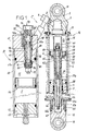
- this hydraulic shock absorber is made up of two elements, namely a shock absorber A and a oleopneumatic tank R, these two elements being connected by a conduit hydraulic C.
- the shock absorber A is composed of a tubular body 2, one of the ends is sealed off by a damper head 3 and the other end of which is closed off by a rod guide 4 traversed, axially and with seal, by a tubular rod 5 linked to a piston 6.
- This piston divides the inner chamber of the shock absorber into a chamber of large section G and a small section room P.
- a blind bore 7 made in the head 3 and communicating by a channel 8 with a screwed hydraulic connection 9 in the end of this channel and ensuring the hydraulic connection with the conduit C.
- the head 3 is also provided with an eye 10 for fixing the shock absorber on the vehicle as well as the head 12, screwed to the end of the rod 5.
- the head 3 of the body and the head 12 of the rod are each secured to cups 13 and 14 respectively, on which the opposite ends of a tensioning helical compression spring 15 constantly return the shock absorber to the extended position.
- the piston 6 is monolithic with, on the one hand, a chimney 16 and, on the other hand, a tail tubular 17.
- a threaded portion 17a Starting from the piston towards the end of the tail 17, this the latter comprises, externally and successively, a threaded portion 17a, a cylindrical part of smaller diameter 17b, a part still having a smaller diameter 17c and, finally, a threaded portion of smaller diameter 17d.
- the tail 17 is crossed, going from its lower end towards the piston 6, by an axial bore 18, by a larger axial bore 19 diameter, and whose transition with a bore 20 formed in the chimney 16 is provided by a frustoconical seat 22.
- the rod 5 which externally is cylindrical over its entire length, with the exception of its lower end fitted with a 5a thread allowing its connection by screwing with the head 12, internally comprises a succession of axial bores of increasing diameters, namely a bore 23, a bore 24, a threaded bore 25 able to cooperate with the threaded end 17d of the piston and a smooth bore 26, able to cooperate with the smooth cylindrical part 17c of the piston to improve its positioning.
- the piston 6 is crossed vertically and right through by longitudinal channels 27 which may be circular or have any other section, as shown in figure 8. On its periphery, the piston 6 is equipped a groove for a filling 28.
- the bore 20 of the chimney 16 has an internal diameter which substantially corresponds, apart from the functional clearance, to that outside of a valve 29, frustoconical and extended towards a tail 30 whose length is greater to the value of its diameter.
- This valve has an axial bore 32 for the passage of an axial rod 33.
- the upper end of the axial rod 33 is provided with a thread 34 and its lower end is provided with a head shouldered 35 comprising an axial thread 36 allowing its connection with the threaded end 37a of a control rod 38, visible in FIG. 1.
- This flow passes through the radial holes 43, the channel 42, between the valve 29 and its seat 22, then comes into the chamber G in passing through the chimney 16 by radial holes 44, cylindrical and practically tangent to the face of the piston 6 turned towards the side of the large section G.
- Adjustment of the setting of the valve 29, therefore of the compression of the spring washers 33 by the nut 40, is effected by the control rod 38 which, slidingly mounted in the bore 23 of the damper rod 5, exceeds from the end thereof to cooperate with control means.
- these means of controls include socket 45, threaded wheel 46 and pin through 47.
- the sleeve 45 has a smooth bore through which it is sliding mounted on the cylindrical end piece 12a of the head 12. Externally, it includes a thread 45a which cooperates with the internal thread of the thumbwheel 46, mounted in rotation on the end piece 12a but locked in translation relative to this nozzle by a stop ring not shown.
- Pin 47 which is arranged diametrically in the end of the control rod 38, passes through the end piece 12a by lights 12b, visible in FIG. 1, and is linked by its two ends to the sleeve 45 which is thus locked in rotation with the possibility of translation vertical.
- This washer visible on an enlarged scale in FIG. 7, is produced in a spring steel, extends radially on either side of the channels 27 and is pinched, by its inner edge and in a 6th recess of the piston 6, by the end face of a plating ring 52, screwed onto the threaded part 17a of the tail 17 of the piston.
- the non-return lamellar valve constituted has no possibility of adjustment in operation, which differentiates it from prior art shock absorbers and what is without interest here, since all the compression settings are made on the head of the tank, as will be specified later.
- this face opens at least one circular groove 53 making communicate the channels 27 between them and reducing the bonding effort.
- the monolithism of the piston 6 makes it possible to give its tail 17 a larger diameter and, with equal resistance compared to a tubular rod of smaller outside diameter, to create a channel inside this piston annular 42 of larger section, facilitating fluid transfers and retaining a laminar regime to these transfers, which has the advantage of not not affect the settings of the axial valve and avoid its flapping, so to improve the general functioning of the piston in the exhaust phase.
- the position and distribution of the channels 27 used for the passage oil in the compression phase are no longer defined according to the dimension of the connecting members of the piston with its rod, and can therefore be arranged and organized only according to hydraulic criteria.
- That of the embodiment shown in Figure 1 is composed of a tubular body 60 provided with internal threads 62 at each of its ends, threads in which are screwed, respectively, a head 61, and a plug 63.
- the body 60 contains a divider piston 64 dividing it into a chamber F, containing a gas under pressure, and a chamber H containing a hydraulic fluid.
- Figures 9 and 10 show that the head 61 comprises a cpnduit radial 65 opening to the outside via a larger diameter threaded bore 66, able to cooperate with the threaded end of a fitting 9 fitted to the other end of the connecting duct C with the shock absorber.
- Channel 65 communicates with a longitudinal channel 67, at the end of which is mounted a check valve return 68 opening when the shock absorber is in the extension phase for favor the return of hydraulic fluid to chamber G.
- Figure 1 which therefore represents a tank equipped with means adjustment of low and high speeds comprises, in known manner, a adjustment rod 70 with an upper end provided with a thread 71 and a lower end disposed in the hydraulic chamber H.
- the latter serves as a guide for a valve 72 and is provided with a thread for a nut 73 determining the calibration of spring washers 74, pressing on the valve.
- the valve 72 which is here a flat valve, does not bear against the internal face 61 a of the head 61 but against the end face 82 of a tubular body 75, itself screwed by a thread 76 in a threaded part of the bore 69a of the head.
- This body tubular 75 protrudes outside of the head 61 by a portion 75a, grippable by a tool allowing it to rotate, and comprising a shoulder 75b for the support of a locking screw 77.
- the outer end of the body 75 also has an internal thread into which the thread 71 of the adjustment rod 70.
- the tubular body 75 has a groove 75c forming, with the bore 69a formed in the head 61, an annular channel which, isolated by seals 78, communicates with channel 65 and, consequently, with the large section chamber G of the shock absorber.
- the back of the throat 75c is crossed by several radial holes 79 which allow the fluid hydraulic to enter an annular channel 80 formed between a narrowing of the rod 70 and the internal bore of the annular body 75.
- the tubular body 75 comprises, at its end disposed in the hydraulic chamber H, at least one radial groove 81 creating, between its end face 82 forming a seat for the valve and the valve 72, a leak whose flow rate can be adjusted from a zero value to a maximum value, depending on the distance S between the active face 72a of the valve 72 and the internal face 61a of the head 61.
- the leak constituted by the groove 81 is sufficient to let the flow pass without opposing the action of the spring over a more or less long stroke depending on the setting.
- C1 is the curve representative of the variation spring 15, and C2, C3, C4 the damping curves obtained for road, sport and track use, respectively settings of the preload value, therefore of the leak rate, allow, without change the stiffness of the spring, change the stiffness of the whole the shock absorber when needed.
- Curve C2 shows that for use road a significant leak favors the action of the spring, therefore comfort, while that for sporty driving, less leakage allows to obtain the curve C3, where the predominant action of the spring is quickly replaced by hydraulic damping, necessary to control the movements of the body and allow more precise handling on the supports.
- Curve C4 shows that for use on the track, the leakage is even more reduced so that the hydraulic damping acts as soon as possible and is added to that of the spring to improve grip on the ground and power transmission.
- the device according to the invention has no influence, and in addition allows to adjust at will the preload according to the quality of the soil, type of pipe, but also the temperature of the hydraulic fluid since, due to the arrangement outside, on the head of the tank of all of the adjustment means, it is very easy to readjust these adjustments after the shock absorber has reached operating temperature.
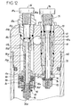
- the embodiment shown in Figure 12 relates to a tank head 61 which, in addition to the adjustment means previously described, comprises, in a channel 69b parallel to channel 69a, means for setting for high and very high speeds.
- These means include a tubular body 85 traversed axially and longitudinally by a rod adjustment 86.
- the tubular body 85 comprises, going from top to bottom, a head 85a protruding outside the head 61 of the tank and suitable for being driven by means allowing adjustment, a threaded part 85b by which it is screwed into a thread of the body 61, a cylindrical part 85c carrying the sealing means with the bore 69b of the body 61, a narrowing 85d and a tubular part of smaller outside diameter 85e.
- the rod 86 is provided with an actuating head 86a projecting beyond the outside of the tank and of the head of the tubular body 85, with a threaded part 86b by which it is screwed into a threaded bore of the body 85, of a cylindrical part 86c, slidably mounted in a cylindrical bore of the body 85 and carrying the sealing means, from a portion of smaller diameter 86d slidingly mounted in a bore of the tubular body 85 and with a threaded end 86e.
- On the part 85e of the tubular body 85 is mounted sliding a flat valve 88 which cooperates with a seat formed by the face inner end 61a of the body 61.
- This valve 88 is pressed onto its seat by a stack of spring washers 89 also bearing on a nut 90 screwed onto the threaded end 85f of the tubular body. Washer stack 89 and the nut 90 are arranged inside the skirt 92a of a bell 92. The diametrical wall 92b thereof is pressed against the end face of the body tubular 85 by a stack of spring washers 93, arranged around the threaded part 86e and whose calibration is determined by a nut 94 screwed onto this 86th threaded part.
- Figure 12 shows that under normal conditions adjustment, the edge of the skirt 92a of the bell 92 is spaced from the valve 88 by a distance E.
- the screw 70 is assigned to an adjustment in compression at low speeds, the tubular body 75 at the setting for the medium speed, the tubular body 85 at the high speed setting and the axial rod 86 for setting very high speeds.
- the tubular body 85 it is easily understood that its screwing or unscrewing by relative to the head 61 makes it possible to modify the position of the nut 90 relative to the valve 88 and, consequently, to modify the tightening ratio of the washers elastic 89.
- the rod 86 its screwing or unscrewing relative to the body 85, allows to move the nut 94, to modify the tightness of the stack of washers 93 pressing the bell 92 on the end of the body 85, so the calibration provided by these washers.
- the damping control is provided by the valve 72, as described above with reference to the figure 1.
- control damping is first provided by spring 15, as shown in C6 figure 15 then is assisted by hydraulic damping up to a threshold determined by the opening of the high speed valve 88 which, by lifting from its seat, frees the channel 69b and allows the fluid to enter the chamber H.
- the curves C7, C8, C9 and C10 of figure 15 corresponding to a use road, track, sport and all terrain, show that this threshold can be adjusted according to the specific needs of use of the vehicle.
- valve 88 comes into contact with the skirt 92a and can move this skirt against the stack of washers 93 in increasing the cross section of the fluid leaving the channel 69b, for enter the chamber H of the reservoir, i.e. by reducing the effect of braking provided by the valve.
- this change in conditions amortization is represented by curves C7a, C8a, C9a and C10a.
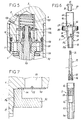
- the mechanical stop of the piston 6 on the head 3 of the damper body, the chimney 16 integral with the piston cooperates with the blind bore 7 of the head 3 to form the hydraulic limit stop.
- the bore blind 7 has a diameter which is equal, apart from the functional clearance, to the diameter outside of the chimney 16, so that, at the end of the race, this chimney closes gradually channel 8, until the complete obturation shown in figure 2.
- a stopper has an all-terrain use because, during a jump, it avoids shocks important on the mechanical stops of the vehicle.
- the chimney 16 is capped by a cup 100 whose outside diameter is equal, at play close to the inside diameter of the blind bore 7.
- This cup is slidably mounted on the chimney and is positioned in relation to it by an axial adjustment rod 102 passing longitudinally through the rod 33 and the control rod 38 to reach adjustment means arranged on the lower head 112 of the shock absorber.
- the upper end of the rod 102 is disposed with play in an axial bore 100a of the sleeve 100 and is linked to the diametral wall of this socket by a diametral pin 103. Its lower end is linked by a diametric pin 104 to a socket 105, sliding mounted on the tubular endpiece 112a of the head 112.
- the pin crosses this tubular endpiece through lights 106.
- the socket 105 is provided an external thread which cooperates with the thread 107 of a thumb wheel 108, free rotationally mounted on the tip 112a and locked in translation relative to this tip. The rotation of the wheel 108 causes the displacement longitudinal of the sleeve 105 on the tip 112a and, consequently, the longitudinal displacement of the rod 102 and of the cup 100.
- This arrangement requires modifying the connection means of the hollow rod 38 for controlling the adjustment of the valve 29 with its socket 45.
- the diametric pin 47 shown in Figure 1
- the diametric pin 47 is replaced by two transverse pins 47a, 47b arranged on either side of the rod axial 102. These two pins pass through the wall of the tubular endpiece 112a by two lights 112b.
- the sleeve 45 cooperates with a wheel 46 which is wedged in longitudinal translation, on one side, by pressing on the thumb wheel 108, itself resting on the head 112, and, on the other side, by a stop ring 109.
- the stop hydraulic includes, in addition to the chimney 16 which is shorter than in the previous embodiments, a socket 120 which is mounted sliding in the blind bore 7 between a position in which its edge rear 120a releases channel 8 and a position in which it closes completely this channel.
- the socket 120 is provided with a front flange 122 which, on one side, receives support from the end face of the chimney 16 and on the other side, the support of a return spring 123.
- the spring 123 is disposed around the socket 120 in a housing 124 formed in the head 3 for the collar 122, while in FIG. 5, it is arranged inside the socket and, partly in the blind housing 7 against the bottom of which it comes take support.
- the flange 122 is moves in the housing 124 in which it is trapped by a rod stop 125 against which it abuts when it is in the rest position.
- the adjustable hydraulic stops are more particularly interesting for sports or track use, because they allow you to adjust supports at high speed and to prevent the vehicle from rolling.
- the versatile shock absorber and multiple settings allows to quickly modify the settings, for example to switch from road use to sport use or on the track, thus avoiding the use of anti-roll bars.
- the speed of changes to the settings allows the vehicle to be adapted related to the terrain encountered: mud, dry, flat, bumpy, very bumpy, need for jumps //
Landscapes
- Engineering & Computer Science (AREA)
- General Engineering & Computer Science (AREA)
- Mechanical Engineering (AREA)
- Fluid-Damping Devices (AREA)
- Vibration Dampers (AREA)
- Solid-Sorbent Or Filter-Aiding Compositions (AREA)
Claims (10)
- Hydraulische Mehrzweck-Fahrzeugdämpfungsvorrichtung, umfassend:dadurch gekennzeichnet, dass die Gesamtheit der einstellbaren Mittel (70, 71), welche die Dämpfungszustände in der Kompressionsphase bestimmen, im Kopf (61) des Speicherbehälters (R) angeordnet ist, und von außen ohne Demontage zugänglich ist, und dass diese Mittel (71), die die Kompression bei geringer Geschwindigkeit regulieren, einen rohrförmigen Vorlasteinstellkörper (75) umfassen, der in den Kopf (61) des Speicherbehälters eingeschraubt ist und der nach außen über diesen vorsteht durch einen Betätigungskopf (75a) und, im Inneren des Speicherbehälters durch ein aktives Ende in Form eines Sitzes (82) vorsteht, wobei dieser rohrförmige Körper (75):einen Dämpfungsvorrichtungskörper (2), welcher durch einen Kolben (6) in eine Kammer mit großem Abschnitt (G) und eine Kammer mit kleinem Abschnitt (P) geteilt wird;einen ölpneumatischen Speicherbehälter (R), dessen hydraulische Kammer (H) mit der Kammer mit großem Abschnitt (G) des Dämpfungsvorrichtungskörpers in Verbindung steht;eine mobile Einheit, zusammengesetzt aus einem Kolben (6) mit seinem rohrförmigen Schaft (5), wobei der Kolben einen Ringkanal (42) aufweist, der mit der Kammer mit kleinem Abschnitt (P) in Verbindung steht und durch einen Sitz (22) abgeschlossen ist, welcher mit einem axialen Rückschlagventil (29) zusammenwirkt, weiches in der Kompressionsphase geschlossen ist, wobei der Kolben (6) von zwei Längskanälen (27) durchquert wird, welche in der Dekompressionsphase geschlossen sind durch ein lamellenartiges Rückschlagventil (50);einen axialen Schaft (33), welcher in der mobilen Einheit angeordnet ist und dessen in die Kammer mit großem Abschnitt (G) vorstehendes Ende (34) Ausgleichsmittel (31, 40) des axialen Ventils (29) trägt, wohingegen das andere Ende am rohrförmigen Schaft (5) vorsteht, um mit den Ausgleichseinstellmitteln dieses axialen Ventils (29) zusammenzuwirken;einen Speicherbehälterkopf (61), welcher mit Kompressionseinstellmitteln ausgerüstet ist, wenigstens für geringe Geschwindigkeiten, wobei diese Mittel eine Einstellschraube (70) umfassen, deren Schaft, der in einem mit der Kammer mit großem Abschnitt (G) in Verbindung stehenden Kanal (69a) angeordnet ist, an seinem in die hydraulische Kammer (H) des Speicherbehälters (R) einmündenden Ende ein einstellbares mit einem Sitz zusammenwirkendes Ausgleichsventil (72) trägt,und eine schraubenförmige Feder (15), welche um den Dämpfungsvorrichtungskörper (2) angeordnet ist und welche sich auf Federtellem (13, 14) abstützt, welche mit dem Körper (2) beziehungsweise mit einem Ende des Schafts (5) des Kolbens verbunden sind,a) in Verbindung steht mit der Kammer mit großem Abschnitt (G) der Dämpfungsvorrichtungb) axial von der Einstellschraube (70) durchquert wird, wobei diese Schraube in ihrem oberen Teil verschraubt ist und an ihrem inneren Ende im Speicherbehälter (R) das Ventil (72) mit seinen Federausgleichsmitteln trägt,c) in seinem als Sitz (82) für das Ventil (72) geformten Teil wenigstens eine radiale Nut (81) aufweist, welche einen die Vorlast festlegenden Fluchtkanal bildet, wobei der Durchflussabschnitt dieses Kanals bestimmt wird zwischen einem Nullwert und einem Maximalwert durch den Abstand (S) zwischen einerseits der Endseite (82) des rohrförmigen Körpers (75) und andererseits der Innenseite (61a) des Kopfs (61) des Speicherbehälters.
- Hydraulische Mehrzweckdämpfungsvorrichtung nach Anspruch 1, dadurch gekennzeichnet, dass das lamellenartige Ventil (50), welche mit den im Kolben (6) ausgebildeten Längskanälen (27) zusammenwirkt, durch eine einzelne Ringfeder (50) gebildet ist, deren innerer Rand an einer Spannfläche (6e) des Kolbens (6) durch die Endseite eines vorspringenden Rings (52) eingeklemmt ist, wobei dieser mit einer Verlängerung (17) des Kolbens (6) verschraubt ist.
- Hydraulische Mehrzweckdämpfungsvorrichtung nach Anspruch 2, dadurch gekennzeichnet, dass die Seite (6a) des Kolbens (6), an der sich das lamellenartige Ventil (50) andrückt, wenn er sich in Ruhe oder in der Kompressionsphase befindet, im Anschlöagsbereich des Ventils (50) umfasst: wenigstens eine kreisförmige Vertiefung (53), welche die Öffnungen der den Kolben durchquerenden Kanäle (27) verbindet, wodurch die Belags- und Klebefläche zwischen Ventil (27) und der Seite (6a) des Kolbens verkleinert wird und ein Kissen von dämpfendem Fluid gebildet wird.
- Hydraulische Mehrzweckdämpfungsvorrichtung nach Anspruch 1, dadurch gekennzeichnet, dass Mittel zum Einstellen der Kompression bei hoher Geschwindigkeit, welche im Kopf (61) des Speicherbehälters mit Mitteln zur Einstellen bei sehr hoher Geschwindigkeit angeordnet sind, durch einen rohrförmigen Körper (85) gebildet sind, welcher den Kopf (61) durchquert und dessen äusseres Ende ausserhalb dieses Kopfes in diesem Kopf verschraubt ist, wohingegen sein inneres Ende, welches über einen Kanal (69b) vorsteht welcher im Kopf ausgespart ist, ein Ventil (88) trägt, welches mit einem am Ende des Kanals (69b) geformten Sitz zusammenwirkt, wobei die Öffnungsbedingungen dieses Ventil (88) bei hoher Geschwindigkeit vom Ausgleich der Federscheiben (89) abhängt, welche um das innere Ende des rohrförmigen Körpers (75) und zwischen dem Ventil (88) und einer auf dieses Ende geschraubten Mutter (90) angeordnet sind, und bei sehr hohen Geschwindigkeiten vom Ausgleich der Federscheiben (93) abhängt, welche um das tiefere Ende am Speicherbehälter (R) eines Einstellschaft (86) angeordnet sind, welcher den rohrförmigen Körper (75) durchdringt und in diesen eingeschraubt ist, wobei diese Scheiben (93) zwischen einerseits einer auf diesem Schaft (86) geschraubten Mutter (94) und andererseits der diametralen Wandung (92b) einer Glocke (92) angeordnet sind, und zwar in Anschlag auf dem Ende des rohrförmigen Körpers (75), und deren Verkleidung (92a), welche die Ausgleichsmittel für hohe Geschwindigkeit umgibt, sich in Richtung des Ventils (88) erstreckt, wobei zwischen ihrem Rand und dem Ventil ein Spiel (E) gebildet ist, welches ihrem Öffnungsweg beim Betrieb bei hoher Geschwindigkeit entspricht.
- Hydraulische Mehrzweckdämpfungsvorrichtung nach Anspruch 1, dadurch gekennzeichnet, dass der Kolben (6) eine Einheit bildet mit einem Endstück (17) und einem rohrförmigen Kamin (16), welcher in die Kammer mit großem Abschnitt (G) vorsteht und dessen innere Bohrung (20) die Translationsführung des Kopf des axialen sich bei Druckminderung öffnenden Rückschlagventils (29) gewährleistet, wobei die Wandung dieses Kamins (16) in der Nähe des Kolbens (6) und des Sitzes für das axiale Ventil von mehreren radialen Durchflusskanälen (44) für das Fluid durchquert wird, wohingegen der Sitz für das Ventil (29) durch eine kegelstumpfartige Öffnung (22) gebildet ist, welche im Kolben (6) ausgebildet ist und dazu eingerichtet ist, den kegelstumpfartigen Kopf des Ventils aufzunehmen, wobei diese Öffnung (22) im Kolben durch eine zylindrische Bohrung (19) im Kolben verlängert wird, welche mit dem zylindrischen Endstück (30) des Ventils (29) zusammenwirkt, um einen ringförmigen Kanal (42) zur Stabilisierung des Durchsatzes des bei Druckminderung durchströmenden Fluids zu bilden, wobei der Kanal (42) durch zwei radiale Löcher (43) gespeist wird, welche im zugehörigen rohrförmigen Teil des Endstücks (17) des Kolbens (6) ausgebildet sind.
- Hydraulische Mehrzweckdämpfungsvorrichtung nach Anspruch 5, dadurch gekennzeichnet, dass der Kamin (16) des Kolbens mit einer Scheinbohrung (7) zusammenwirkt, welche im Kopf (3) der Dämpfungsvorrichtung ausgebildet ist und mit dem Speicherbehälter (R) durch einen Verbindungskanal (8) in Verbindung steht, um einen hydraulischen Anschlag für einen progressiven Stopp des Kolbens (6) am Ende des Kompressionsvorgangs zu bilden.
- Hydraulische Mehrzweckdämpfungsvorrichtung nach Anspruch 6, dadurch gekennzeichnet, dass die Scheinbohrung (7) des Kopfs (3) der Dämpfungsvorrichtung einen inneren Durchmesser aufweist, welcher nahe dem zweckmäßigen Spiel, gleich wie der äußere Durchmesser des Kamins (16) ist, und zwar derart, dass am Ende der Kompressionsphase der in die Scheinbohrung (7) eindringende Kamin (16) zunehmend die Verbindung mit dem Speicherbehälter (R) verschließt.
- Hydraulische Mehrzweckdämpfungsvorrichtung nach Anspruch 6, dadurch gekennzeichnet, dass die Scheinbohrung (7) des Kopfs (3) der Dämpfungsvorrichtung eine Hülse (120) enthält, welche durch eine Feder (123) gegen einen Anschlag (125) zurückgestellt wird, und zwar derart, dass ihr hinterer Rand den Verbindungskanal (8) mit dem Speicherbehälter (R) freigibt, wobei diese Hülse (120) auf ihrem vorderen Rand mit einem Flansch (122) ausgerüstet ist, welcher in der Verschiebungsbahn des Kamins (16) des Kolbens angeordnet ist, und zwar derart, dass am Ende der Kompressionsphase der Kamin (16) die Hülse (120) in die Scheinbohrung (7) verschiebt, wobei durch ihren hinteren Rand der Verbindungskanal (8) mit dem Speicherbehälter (R) zunehmend verschlossen wird.
- Hydraulische Mehrzweckdämpfungsvorrichtung nach Anspruch 6, dadurch gekennzeichnet, dass der Kamin (16) des Kolbens (6) von einer Schale (100) bedeckt ist, deren äußerer Durchmesser nahe dem zweckmäßigen Spiel gleich ist wie der Durchmesser der Scheinbohrung (7) des Kopfs (3) der Dämpfungsvorrichtung, wobei diese Schale (100) durch Längsverschiebung bezüglich des Kamins (16) verstellbar ist mittels eines axialen Einstellschafts (102), welcher verschiebbar im Einstellschaft (33, 38) des Rückschlagventils (29) angebracht ist und durch sein über das Ende dieses Schraub-Einstellschafts vorstehendes Ende mit Einstellmitteln (104, 405, 108) verbunden ist, welche es erlauben, die Anfangsposition des Verschlusses des Verbindungskanals (8) mit dem Speicherbehälter (R) durch diese Schale (100) zu verändern.
- Hydraulische Mehrzweckdämpfungsvorrichtung nach Anspruch 1, dadurch gekennzeichnet, dass die Summe der Durchflussquerschnitte der Längskanäle (27), welche den Kolben (6) durchqueren, um wenigstens 50% grösser ist als der Querschnitt des Kanals (8) der Entleerung zum Speicherbehälter (R) hin.
Priority Applications (1)
| Application Number | Priority Date | Filing Date | Title |
|---|---|---|---|
| DK02758507T DK1402196T3 (da) | 2001-06-12 | 2002-06-11 | Polyvalent hydraulisk stöddæmper til köretöj |
Applications Claiming Priority (3)
| Application Number | Priority Date | Filing Date | Title |
|---|---|---|---|
| FR0107993A FR2825767B1 (fr) | 2001-06-12 | 2001-06-12 | Amortisseur hydraulique polyvalent pour vehicule |
| FR0107993 | 2001-06-12 | ||
| PCT/FR2002/001994 WO2002101261A1 (fr) | 2001-06-12 | 2002-06-11 | Amortisseur hydraulique polyvalent pour vehicule. |
Publications (2)
| Publication Number | Publication Date |
|---|---|
| EP1402196A1 EP1402196A1 (de) | 2004-03-31 |
| EP1402196B1 true EP1402196B1 (de) | 2004-12-15 |
Family
ID=8864465
Family Applications (1)
| Application Number | Title | Priority Date | Filing Date |
|---|---|---|---|
| EP02758507A Expired - Lifetime EP1402196B1 (de) | 2001-06-12 | 2002-06-11 | Hydraulischer mehrzweckstossdämpfer für fahrzeug |
Country Status (12)
| Country | Link |
|---|---|
| US (1) | US20050173213A1 (de) |
| EP (1) | EP1402196B1 (de) |
| JP (1) | JP2004529304A (de) |
| AT (1) | ATE285043T1 (de) |
| AU (1) | AU2002324093B8 (de) |
| CA (1) | CA2449668A1 (de) |
| DE (1) | DE60202291T2 (de) |
| ES (1) | ES2235075T3 (de) |
| FR (1) | FR2825767B1 (de) |
| PT (1) | PT1402196E (de) |
| RU (1) | RU2290547C2 (de) |
| WO (1) | WO2002101261A1 (de) |
Cited By (1)
| Publication number | Priority date | Publication date | Assignee | Title |
|---|---|---|---|---|
| WO2008122804A3 (en) * | 2007-04-10 | 2008-12-18 | Joseph Richard Andrew Hunter | Suspension systems |
Families Citing this family (18)
| Publication number | Priority date | Publication date | Assignee | Title |
|---|---|---|---|---|
| US10900539B2 (en) | 2005-12-30 | 2021-01-26 | Fox Factory, Inc. | Fluid damper having a damping profile favorable for absorbing the full range of compression forces, including low- and high-speed compression forces |
| US9108485B2 (en) | 2009-01-09 | 2015-08-18 | Fox Factory, Inc. | Adjustable blow-off suspension |
| US8807300B2 (en) * | 2009-10-26 | 2014-08-19 | Fox Factory, Inc. | Methods and apparatus for managing pressurized gas in fluid dampers |
| US10953716B2 (en) | 2009-10-26 | 2021-03-23 | Fox Factory, Inc. | Methods and apparatus for managing pressurized gas in fluid dampers |
| US9573435B2 (en) * | 2013-09-29 | 2017-02-21 | Elka Suspension Inc. | Dual inline hydraulic device |
| EP2913460B1 (de) * | 2014-02-19 | 2017-08-23 | Chihiro Sangyo Co., Ltd. | Dämpfungsvorrichtung für ein Gebäude |
| CN104482100A (zh) * | 2014-12-04 | 2015-04-01 | 成都唯昂新材料有限公司 | 一种回弹性油压控制杆组的螺牙油量控制装置 |
| EP3759373A4 (de) * | 2018-02-27 | 2022-03-16 | ClearMotion, Inc. | Durch eine röhre gehende aktiver aufhängungsvorrichtung |
| CN108999912B (zh) * | 2018-08-10 | 2020-10-20 | 上海曼杰汽车精密零部件有限公司 | 避振器 |
| CN109648354B (zh) * | 2018-12-13 | 2023-07-25 | 广东工业大学 | 一种中间调节刚度的刚柔耦合平台及运动平台 |
| IL266688B2 (en) * | 2019-05-16 | 2024-03-01 | Evco Pro 2018 Ltd | An automotive hydraulic shock absorber |
| US12496867B2 (en) | 2020-02-27 | 2025-12-16 | Fox Factory, Inc. | Hydraulically-adjustable preload and/or cross-over |
| US11840120B2 (en) * | 2020-02-27 | 2023-12-12 | Fox Factory, Inc. | IFP shock with automatically adjustable ride height |
| CN111649092A (zh) * | 2020-06-04 | 2020-09-11 | 江苏三尔汽车部件有限公司 | 一种用于新能源汽车的后减震器 |
| CN111911580B (zh) * | 2020-08-21 | 2025-01-28 | 浙江永贵电器股份有限公司 | 一种油压减振器活塞单元及其装配方法 |
| CN112389859B (zh) * | 2020-11-27 | 2022-05-27 | 桂林航天工业学院 | 一种可减振的电机固定装置 |
| US11738619B1 (en) * | 2022-09-28 | 2023-08-29 | Liquidspring Technologies, Inc. | Variable rate liquid spring suspension system exhibiting low variance in suspension frequency |
| AU2023353059A1 (en) | 2022-09-28 | 2025-04-24 | Liquidspring Technologies, Inc. | Variable rate liquid spring suspension system exhibiting low variance in suspension frequency |
Family Cites Families (9)
| Publication number | Priority date | Publication date | Assignee | Title |
|---|---|---|---|---|
| NL8600211A (nl) * | 1986-01-30 | 1987-08-17 | White Power Prod Bv | Hydraulische schokdemper. |
| US4958706A (en) * | 1988-11-14 | 1990-09-25 | Richardson Donald G | Adjustable shock absorbers |
| US4936424A (en) * | 1989-05-09 | 1990-06-26 | Costa Vince F | Hydraulic shock absorber with pressure sensitive external valving |
| RU2020320C1 (ru) * | 1990-12-29 | 1994-09-30 | Акционерное общество открытого типа "Завод им.В.А.Дегтярева" | Амортизатор с регулируемой силой гидродемпфирования |
| RU2031275C1 (ru) * | 1991-04-04 | 1995-03-20 | Валентин Николаевич Власов | Амортизатор с регулируемой силой грузоподъемности и гидродемпфирования |
| GB9225018D0 (en) * | 1992-11-30 | 1993-01-20 | Nelms Charan | Shock absorber |
| FR2751713B1 (fr) * | 1996-07-24 | 1998-09-18 | Donerre Amortisseur Soc | Systeme amortisseur a huile |
| FR2764353A1 (fr) * | 1997-06-05 | 1998-12-11 | Donerre Amortisseur | Amortisseur a huile |
| US6318525B1 (en) * | 1999-05-07 | 2001-11-20 | Marzocchi, S.P.A. | Shock absorber with improved damping |
-
2001
- 2001-06-12 FR FR0107993A patent/FR2825767B1/fr not_active Expired - Fee Related
-
2002
- 2002-06-11 US US10/479,709 patent/US20050173213A1/en not_active Abandoned
- 2002-06-11 PT PT02758507T patent/PT1402196E/pt unknown
- 2002-06-11 AU AU2002324093A patent/AU2002324093B8/en not_active Ceased
- 2002-06-11 EP EP02758507A patent/EP1402196B1/de not_active Expired - Lifetime
- 2002-06-11 AT AT02758507T patent/ATE285043T1/de not_active IP Right Cessation
- 2002-06-11 RU RU2004100317/11A patent/RU2290547C2/ru not_active IP Right Cessation
- 2002-06-11 JP JP2003503987A patent/JP2004529304A/ja active Pending
- 2002-06-11 CA CA002449668A patent/CA2449668A1/fr not_active Abandoned
- 2002-06-11 WO PCT/FR2002/001994 patent/WO2002101261A1/fr not_active Ceased
- 2002-06-11 ES ES02758507T patent/ES2235075T3/es not_active Expired - Lifetime
- 2002-06-11 DE DE60202291T patent/DE60202291T2/de not_active Expired - Fee Related
Cited By (2)
| Publication number | Priority date | Publication date | Assignee | Title |
|---|---|---|---|---|
| WO2008122804A3 (en) * | 2007-04-10 | 2008-12-18 | Joseph Richard Andrew Hunter | Suspension systems |
| US8931602B2 (en) | 2007-04-10 | 2015-01-13 | Joseph Richard Andrew Hunter | Suspension systems |
Also Published As
| Publication number | Publication date |
|---|---|
| CA2449668A1 (fr) | 2002-12-19 |
| AU2002324093B2 (en) | 2006-11-23 |
| AU2002324093B8 (en) | 2006-11-30 |
| EP1402196A1 (de) | 2004-03-31 |
| RU2004100317A (ru) | 2005-02-10 |
| ATE285043T1 (de) | 2005-01-15 |
| DE60202291T2 (de) | 2006-03-02 |
| DE60202291D1 (de) | 2005-01-20 |
| US20050173213A1 (en) | 2005-08-11 |
| PT1402196E (pt) | 2005-05-31 |
| ES2235075T3 (es) | 2005-07-01 |
| WO2002101261A1 (fr) | 2002-12-19 |
| RU2290547C2 (ru) | 2006-12-27 |
| FR2825767A1 (fr) | 2002-12-13 |
| JP2004529304A (ja) | 2004-09-24 |
| FR2825767B1 (fr) | 2003-08-15 |
Similar Documents
| Publication | Publication Date | Title |
|---|---|---|
| EP1402196B1 (de) | Hydraulischer mehrzweckstossdämpfer für fahrzeug | |
| FR2497895A1 (fr) | Amortisseur hydraulique, notamment pour vehicules a moteur | |
| EP0003458B1 (de) | Dämpfer für ein Fahrzeug mit elastischer Aufhängung | |
| EP0416987B1 (de) | Ventil für hydraulische Flüssigkeit und ein mit einem solchen Ventil ausgerüsteter Dämpfer | |
| WO2009010643A2 (fr) | Amortisseur pour atterrisseur d'aeronef | |
| FR2921893A1 (fr) | Dispositif de controle d'un dispositif amortisseur hydraulique de suspension | |
| FR2552513A1 (fr) | Appareil de suspension de vehicule | |
| FR2775041A1 (fr) | Soupape reagissant en fonction de la pression, notamment pour un amortisseur d'oscillations | |
| FR2608243A1 (fr) | Amortisseur hydraulique | |
| FR2476782A1 (fr) | Amortisseur pour suspension de vehicule automobile | |
| EP2956687B1 (de) | Endlagendämpfung | |
| EP1085232B1 (de) | Einstellvorrichtung eines hydraulischen Stossdämpfers | |
| FR2531169A1 (fr) | Soupape a disque pour amortisseur hydraulique | |
| FR2497894A1 (fr) | Amortisseur hydraulique, pneumatique ou oleopneumatique, notamment pour la suspension des vehicules a moteur | |
| EP1554506A2 (de) | Hydraulischer anschlagpuffer für kraftfahrzeugstossdämpfer, stossdämpfendes system und verfahren zum betrieb eines solchen systems | |
| EP1989464B1 (de) | Als ein federbein montiertes dämpfungssystem mit schneller entspannung | |
| FR2503082A1 (fr) | Suspension de roue, notamment pour motocyclette | |
| FR2803001A1 (fr) | Dispositif d'amortissement a force d'amortissement variable | |
| WO1986007422A1 (fr) | Amortisseur pour element de suspension de vehicule lourd | |
| EP1171724B1 (de) | Asymmetrischer dämpfer für eine radaufhängung eines kraftfahrzeugs | |
| EP0264324B1 (de) | Automatisch regelbare Dämpfungsvorrichtung | |
| CA2563794A1 (fr) | Systeme amortisseur a detente rapide et butee hydraulique de fin de course et procede d'utilisation | |
| FR2736890A1 (fr) | Amortisseur hydroelastique de trainee pour rotor de giravion | |
| FR2993623A1 (fr) | Dispositif amortisseur hydraulique | |
| FR2613011A1 (fr) | Jambe telescopique de suspension pour roue d'un vehicule automobile |
Legal Events
| Date | Code | Title | Description |
|---|---|---|---|
| PUAI | Public reference made under article 153(3) epc to a published international application that has entered the european phase |
Free format text: ORIGINAL CODE: 0009012 |
|
| 17P | Request for examination filed |
Effective date: 20031215 |
|
| AK | Designated contracting states |
Kind code of ref document: A1 Designated state(s): AT BE CH CY DE DK ES FI FR GB GR IE IT LI LU MC NL PT SE TR |
|
| AX | Request for extension of the european patent |
Extension state: AL LT LV MK RO SI |
|
| GRAP | Despatch of communication of intention to grant a patent |
Free format text: ORIGINAL CODE: EPIDOSNIGR1 |
|
| GRAA | (expected) grant |
Free format text: ORIGINAL CODE: 0009210 |
|
| GRAS | Grant fee paid |
Free format text: ORIGINAL CODE: EPIDOSNIGR3 |
|
| AK | Designated contracting states |
Kind code of ref document: B1 Designated state(s): AT BE CH CY DE DK ES FI FR GB GR IE IT LI LU MC NL PT SE TR |
|
| PG25 | Lapsed in a contracting state [announced via postgrant information from national office to epo] |
Ref country code: FI Free format text: LAPSE BECAUSE OF FAILURE TO SUBMIT A TRANSLATION OF THE DESCRIPTION OR TO PAY THE FEE WITHIN THE PRESCRIBED TIME-LIMIT Effective date: 20041215 Ref country code: TR Free format text: LAPSE BECAUSE OF FAILURE TO SUBMIT A TRANSLATION OF THE DESCRIPTION OR TO PAY THE FEE WITHIN THE PRESCRIBED TIME-LIMIT Effective date: 20041215 |
|
| REG | Reference to a national code |
Ref country code: GB Ref legal event code: FG4D Free format text: NOT ENGLISH Ref country code: CH Ref legal event code: EP |
|
| GBT | Gb: translation of ep patent filed (gb section 77(6)(a)/1977) |
Effective date: 20041215 |
|
| REG | Reference to a national code |
Ref country code: IE Ref legal event code: FG4D Free format text: FRENCH |
|
| REF | Corresponds to: |
Ref document number: 60202291 Country of ref document: DE Date of ref document: 20050120 Kind code of ref document: P |
|
| PG25 | Lapsed in a contracting state [announced via postgrant information from national office to epo] |
Ref country code: GR Free format text: LAPSE BECAUSE OF FAILURE TO SUBMIT A TRANSLATION OF THE DESCRIPTION OR TO PAY THE FEE WITHIN THE PRESCRIBED TIME-LIMIT Effective date: 20050315 |
|
| REG | Reference to a national code |
Ref country code: SE Ref legal event code: TRGR |
|
| REG | Reference to a national code |
Ref country code: DK Ref legal event code: T3 |
|
| REG | Reference to a national code |
Ref country code: PT Ref legal event code: SC4A Free format text: AVAILABILITY OF NATIONAL TRANSLATION Effective date: 20050314 |
|
| PG25 | Lapsed in a contracting state [announced via postgrant information from national office to epo] |
Ref country code: CY Free format text: LAPSE BECAUSE OF FAILURE TO SUBMIT A TRANSLATION OF THE DESCRIPTION OR TO PAY THE FEE WITHIN THE PRESCRIBED TIME-LIMIT Effective date: 20050611 |
|
| REG | Reference to a national code |
Ref country code: ES Ref legal event code: FG2A Ref document number: 2235075 Country of ref document: ES Kind code of ref document: T3 |
|
| PLBE | No opposition filed within time limit |
Free format text: ORIGINAL CODE: 0009261 |
|
| STAA | Information on the status of an ep patent application or granted ep patent |
Free format text: STATUS: NO OPPOSITION FILED WITHIN TIME LIMIT |
|
| 26N | No opposition filed |
Effective date: 20050916 |
|
| PGFP | Annual fee paid to national office [announced via postgrant information from national office to epo] |
Ref country code: CH Payment date: 20080612 Year of fee payment: 7 Ref country code: DK Payment date: 20080620 Year of fee payment: 7 Ref country code: ES Payment date: 20080625 Year of fee payment: 7 Ref country code: LU Payment date: 20080627 Year of fee payment: 7 |
|
| PGFP | Annual fee paid to national office [announced via postgrant information from national office to epo] |
Ref country code: AT Payment date: 20080623 Year of fee payment: 7 |
|
| PGFP | Annual fee paid to national office [announced via postgrant information from national office to epo] |
Ref country code: PT Payment date: 20080611 Year of fee payment: 7 Ref country code: MC Payment date: 20080618 Year of fee payment: 7 Ref country code: IT Payment date: 20080619 Year of fee payment: 7 |
|
| PGFP | Annual fee paid to national office [announced via postgrant information from national office to epo] |
Ref country code: DE Payment date: 20080715 Year of fee payment: 7 Ref country code: IE Payment date: 20080625 Year of fee payment: 7 Ref country code: NL Payment date: 20080624 Year of fee payment: 7 Ref country code: SE Payment date: 20080619 Year of fee payment: 7 |
|
| PGFP | Annual fee paid to national office [announced via postgrant information from national office to epo] |
Ref country code: BE Payment date: 20080814 Year of fee payment: 7 |
|
| REG | Reference to a national code |
Ref country code: PT Ref legal event code: MM4A Free format text: LAPSE DUE TO NON-PAYMENT OF FEES Effective date: 20091211 |
|
| BERE | Be: lapsed |
Owner name: *REALISATION ET DEVELOPPEMENT CONCEPT Effective date: 20090630 |
|
| PG25 | Lapsed in a contracting state [announced via postgrant information from national office to epo] |
Ref country code: MC Free format text: LAPSE BECAUSE OF NON-PAYMENT OF DUE FEES Effective date: 20090630 |
|
| REG | Reference to a national code |
Ref country code: CH Ref legal event code: PL |
|
| REG | Reference to a national code |
Ref country code: DK Ref legal event code: EBP |
|
| NLV4 | Nl: lapsed or anulled due to non-payment of the annual fee |
Effective date: 20100101 |
|
| PG25 | Lapsed in a contracting state [announced via postgrant information from national office to epo] |
Ref country code: PT Free format text: LAPSE BECAUSE OF NON-PAYMENT OF DUE FEES Effective date: 20091211 |
|
| REG | Reference to a national code |
Ref country code: IE Ref legal event code: MM4A |
|
| PG25 | Lapsed in a contracting state [announced via postgrant information from national office to epo] |
Ref country code: CH Free format text: LAPSE BECAUSE OF NON-PAYMENT OF DUE FEES Effective date: 20090630 Ref country code: IE Free format text: LAPSE BECAUSE OF NON-PAYMENT OF DUE FEES Effective date: 20090611 Ref country code: LI Free format text: LAPSE BECAUSE OF NON-PAYMENT OF DUE FEES Effective date: 20090630 |
|
| PG25 | Lapsed in a contracting state [announced via postgrant information from national office to epo] |
Ref country code: DE Free format text: LAPSE BECAUSE OF NON-PAYMENT OF DUE FEES Effective date: 20100101 Ref country code: AT Free format text: LAPSE BECAUSE OF NON-PAYMENT OF DUE FEES Effective date: 20090611 Ref country code: BE Free format text: LAPSE BECAUSE OF NON-PAYMENT OF DUE FEES Effective date: 20090630 |
|
| PG25 | Lapsed in a contracting state [announced via postgrant information from national office to epo] |
Ref country code: DK Free format text: LAPSE BECAUSE OF NON-PAYMENT OF DUE FEES Effective date: 20090630 Ref country code: NL Free format text: LAPSE BECAUSE OF NON-PAYMENT OF DUE FEES Effective date: 20100101 |
|
| REG | Reference to a national code |
Ref country code: ES Ref legal event code: FD2A Effective date: 20090612 |
|
| PG25 | Lapsed in a contracting state [announced via postgrant information from national office to epo] |
Ref country code: ES Free format text: LAPSE BECAUSE OF NON-PAYMENT OF DUE FEES Effective date: 20090612 |
|
| PG25 | Lapsed in a contracting state [announced via postgrant information from national office to epo] |
Ref country code: IT Free format text: LAPSE BECAUSE OF NON-PAYMENT OF DUE FEES Effective date: 20090611 |
|
| PG25 | Lapsed in a contracting state [announced via postgrant information from national office to epo] |
Ref country code: LU Free format text: LAPSE BECAUSE OF NON-PAYMENT OF DUE FEES Effective date: 20090611 |
|
| PG25 | Lapsed in a contracting state [announced via postgrant information from national office to epo] |
Ref country code: SE Free format text: LAPSE BECAUSE OF NON-PAYMENT OF DUE FEES Effective date: 20090612 |
|
| PGFP | Annual fee paid to national office [announced via postgrant information from national office to epo] |
Ref country code: FR Payment date: 20110624 Year of fee payment: 10 |
|
| PGFP | Annual fee paid to national office [announced via postgrant information from national office to epo] |
Ref country code: GB Payment date: 20110615 Year of fee payment: 10 |
|
| GBPC | Gb: european patent ceased through non-payment of renewal fee |
Effective date: 20120611 |
|
| REG | Reference to a national code |
Ref country code: FR Ref legal event code: ST Effective date: 20130228 |
|
| PG25 | Lapsed in a contracting state [announced via postgrant information from national office to epo] |
Ref country code: GB Free format text: LAPSE BECAUSE OF NON-PAYMENT OF DUE FEES Effective date: 20120611 Ref country code: FR Free format text: LAPSE BECAUSE OF NON-PAYMENT OF DUE FEES Effective date: 20120702 |