EP1401626B1 - Formwerkzeug zur herstellung eines bauteils mit einer membran - Google Patents
Formwerkzeug zur herstellung eines bauteils mit einer membran Download PDFInfo
- Publication number
- EP1401626B1 EP1401626B1 EP02780740A EP02780740A EP1401626B1 EP 1401626 B1 EP1401626 B1 EP 1401626B1 EP 02780740 A EP02780740 A EP 02780740A EP 02780740 A EP02780740 A EP 02780740A EP 1401626 B1 EP1401626 B1 EP 1401626B1
- Authority
- EP
- European Patent Office
- Prior art keywords
- mould
- pressure
- membrane
- cavity
- diaphragm
- Prior art date
- Legal status (The legal status is an assumption and is not a legal conclusion. Google has not performed a legal analysis and makes no representation as to the accuracy of the status listed.)
- Expired - Lifetime
Links
Images
Classifications
-
- B—PERFORMING OPERATIONS; TRANSPORTING
- B29—WORKING OF PLASTICS; WORKING OF SUBSTANCES IN A PLASTIC STATE IN GENERAL
- B29C—SHAPING OR JOINING OF PLASTICS; SHAPING OF MATERIAL IN A PLASTIC STATE, NOT OTHERWISE PROVIDED FOR; AFTER-TREATMENT OF THE SHAPED PRODUCTS, e.g. REPAIRING
- B29C43/00—Compression moulding, i.e. applying external pressure to flow the moulding material; Apparatus therefor
- B29C43/32—Component parts, details or accessories; Auxiliary operations
- B29C43/36—Moulds for making articles of definite length, i.e. discrete articles
- B29C43/3642—Bags, bleeder sheets or cauls for isostatic pressing
-
- B—PERFORMING OPERATIONS; TRANSPORTING
- B29—WORKING OF PLASTICS; WORKING OF SUBSTANCES IN A PLASTIC STATE IN GENERAL
- B29C—SHAPING OR JOINING OF PLASTICS; SHAPING OF MATERIAL IN A PLASTIC STATE, NOT OTHERWISE PROVIDED FOR; AFTER-TREATMENT OF THE SHAPED PRODUCTS, e.g. REPAIRING
- B29C43/00—Compression moulding, i.e. applying external pressure to flow the moulding material; Apparatus therefor
- B29C43/32—Component parts, details or accessories; Auxiliary operations
- B29C43/36—Moulds for making articles of definite length, i.e. discrete articles
- B29C43/361—Moulds for making articles of definite length, i.e. discrete articles with pressing members independently movable of the parts for opening or closing the mould, e.g. movable pistons
-
- B—PERFORMING OPERATIONS; TRANSPORTING
- B29—WORKING OF PLASTICS; WORKING OF SUBSTANCES IN A PLASTIC STATE IN GENERAL
- B29C—SHAPING OR JOINING OF PLASTICS; SHAPING OF MATERIAL IN A PLASTIC STATE, NOT OTHERWISE PROVIDED FOR; AFTER-TREATMENT OF THE SHAPED PRODUCTS, e.g. REPAIRING
- B29C70/00—Shaping composites, i.e. plastics material comprising reinforcements, fillers or preformed parts, e.g. inserts
- B29C70/04—Shaping composites, i.e. plastics material comprising reinforcements, fillers or preformed parts, e.g. inserts comprising reinforcements only, e.g. self-reinforcing plastics
- B29C70/28—Shaping operations therefor
- B29C70/40—Shaping or impregnating by compression not applied
- B29C70/42—Shaping or impregnating by compression not applied for producing articles of definite length, i.e. discrete articles
- B29C70/44—Shaping or impregnating by compression not applied for producing articles of definite length, i.e. discrete articles using isostatic pressure, e.g. pressure difference-moulding, vacuum bag-moulding, autoclave-moulding or expanding rubber-moulding
-
- B—PERFORMING OPERATIONS; TRANSPORTING
- B29—WORKING OF PLASTICS; WORKING OF SUBSTANCES IN A PLASTIC STATE IN GENERAL
- B29C—SHAPING OR JOINING OF PLASTICS; SHAPING OF MATERIAL IN A PLASTIC STATE, NOT OTHERWISE PROVIDED FOR; AFTER-TREATMENT OF THE SHAPED PRODUCTS, e.g. REPAIRING
- B29C43/00—Compression moulding, i.e. applying external pressure to flow the moulding material; Apparatus therefor
- B29C43/32—Component parts, details or accessories; Auxiliary operations
- B29C43/36—Moulds for making articles of definite length, i.e. discrete articles
- B29C43/3642—Bags, bleeder sheets or cauls for isostatic pressing
- B29C2043/3649—Inflatable bladders using gas or fluid and related details
-
- B—PERFORMING OPERATIONS; TRANSPORTING
- B29—WORKING OF PLASTICS; WORKING OF SUBSTANCES IN A PLASTIC STATE IN GENERAL
- B29C—SHAPING OR JOINING OF PLASTICS; SHAPING OF MATERIAL IN A PLASTIC STATE, NOT OTHERWISE PROVIDED FOR; AFTER-TREATMENT OF THE SHAPED PRODUCTS, e.g. REPAIRING
- B29C43/00—Compression moulding, i.e. applying external pressure to flow the moulding material; Apparatus therefor
- B29C43/32—Component parts, details or accessories; Auxiliary operations
- B29C43/58—Measuring, controlling or regulating
- B29C2043/5875—Measuring, controlling or regulating the material feed to the moulds or mould parts, e.g. controlling feed flow, velocity, weight, doses
- B29C2043/5883—Measuring, controlling or regulating the material feed to the moulds or mould parts, e.g. controlling feed flow, velocity, weight, doses ensuring cavity filling, e.g. providing overflow means
-
- B—PERFORMING OPERATIONS; TRANSPORTING
- B29—WORKING OF PLASTICS; WORKING OF SUBSTANCES IN A PLASTIC STATE IN GENERAL
- B29C—SHAPING OR JOINING OF PLASTICS; SHAPING OF MATERIAL IN A PLASTIC STATE, NOT OTHERWISE PROVIDED FOR; AFTER-TREATMENT OF THE SHAPED PRODUCTS, e.g. REPAIRING
- B29C70/00—Shaping composites, i.e. plastics material comprising reinforcements, fillers or preformed parts, e.g. inserts
- B29C70/04—Shaping composites, i.e. plastics material comprising reinforcements, fillers or preformed parts, e.g. inserts comprising reinforcements only, e.g. self-reinforcing plastics
- B29C70/28—Shaping operations therefor
- B29C70/40—Shaping or impregnating by compression not applied
- B29C70/42—Shaping or impregnating by compression not applied for producing articles of definite length, i.e. discrete articles
- B29C70/46—Shaping or impregnating by compression not applied for producing articles of definite length, i.e. discrete articles using matched moulds, e.g. for deforming sheet moulding compounds [SMC] or prepregs
Definitions
- the invention relates to a mold according to the preamble of claim 1
- Molds for producing plastic components especially from fiber-reinforced sheet-molding compounds (SMC materials) are usually referred to as so Dipping edge tools designed.
- SMC materials fiber-reinforced sheet-molding compounds
- Dipping edge tools consist of two dies, in the Further press punches called, with vertical outside edges, a punch similar to a sleeve over the other punch moves.
- a mold cavity by the press punches is formed, for example, an SMC semi-finished product is placed.
- the SMC semi-finished product comprises a defined weight of Raw material, which generally resins, hardeners, fillers and Comprises fibers (in particular glass fibers) and in layers of rectangular mats is constructed.
- the press punches are now driving on top of each other and press the semi-finished product so that it Form cavity fills.
- the press punches are heatable, so that the hardener cures the resin of the component.
- EP 0 064 247 A1 discloses an injection molding tool described, which is suitable for the production of spectacle lenses is, in which after injection molding a thermoplastic Material through an elastically deformable surface of the Tool is formed into an aspherical surface.
- Such molds are due to their tight tolerances very expensive to produce and therefore very expensive.
- dipping edge tools are for the production of Plastic components therefore necessary, since the Weight metering of raw materials generally not in The desired precision can be made for the use of so-called squeeze edge tools would be necessary.
- Crimping edge tools are constructed such that the Plunger in the closed state lie flat on each other. However, this means that in the closed state no There is scope for a reprint on the semi-finished product. has the semifinished product on too little raw material, the component is not imaged correctly, resulting in inadequate Material properties expressed. Is too much Raw material in the mold cavity, then this is between the Pressed plunger, thereby completely closing the Stamp is prevented.
- the object of the invention is a mold of the above type with reduced tooling costs to be provided by the fluctuations of the Raw material volume and shrinkage during the Component representation are compensated.
- the mold according to the invention according to claim 1 has at least two press punches on. In a closed State, these press punches make up a mold cavity that holds the Contours of a manufactured component is formed.
- At least one press ram is provided with an inventive Diaphragm provided by a pressure with respect to the mold cavity moves inwards and thus the Volume of mold cavity reduced. This way you can additional pressure is exerted on the raw material and Fluctuations in the volume of raw material and shrinkage of the Raw materials are compensated during the molding.
- Particularly preferred membrane of the invention acts Squeezing edge tools whose press dies are closed State plan lie on each other. Such tools are low cost, thereby reducing the process costs Production of SMC components are significantly reduced.
- the membrane is preferably made of a metal that has a high Strength, high heat resistance at a high Has extensibility. Particularly suitable are sheets high strength steels or superplastic alloys (Memory-Matalle).
- the thickness of the membrane is usually between 0.5 mm and 5 mm (claim 2).
- the membrane is preferably welded to the press die. On this way, no raw material can escape from the mold cavity escape. Some advantageous membrane materials like Superplastic alloys are better for fastening with screws or similar fasteners. In this Case, however, is an additional seal z. By neoprene, Rubber or silicone appropriate (claim 3).
- a hydraulic pressure or a Gas pressure which by a pressure medium (eg hydraulic oil or Air) are transmitted.
- the pressure is preferred in one Cavity in the ram, with respect to the mold cavity before the Membrane generated.
- the pressure is generated by a Hydraulic pump or by compressed air or other gases (Claim 4).
- the piston is in Press stamp arranged and presses directly on the membrane.
- the Piston is like the already mentioned flexible container and the Temperature-controlled membrane and thus the temperature of the ram customizable (claim 6).
- the membrane of the invention can be almost all types of forming tools. It is useful at all tools in which during the component presentation a Volume shrinkage of the component material takes place. This applies to pressing tools or injection molding tools Plastic processing, as well as on casting tools or Thixomolding, or thixocasting tools for processing Light metals such as magnesium or aluminum too.
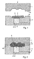
- a pressing tool is shown that a upper ram 1 and a lower ram 2 includes.
- the lower ram 2 includes a membrane 6, the adjacent to a cavity B and made of elastic steel sheet exists (thickness 1 mm).
- the cavity 8 is with a hydraulic fluid 10 filled.
- SMC raw material comprising resin, Binder and fillers
- the upper punch 1 and the lower punch 2 form in the closed position Condition (Fig. 2) a mold cavity 4.
- the mold cavity 4 is formed by the parting surfaces 5 a and 5 b of the stamp. 1 and 2, which form the parting plane 5 in the closed state, vertically enclosed.
- the SMC semi-finished product 3 is designed in its volume that it almost completely fills the mold cavity 4 in the closed state. There a complete equal volume of the SMC semi-finished 3 and the mold cavity 4 under reasonable measures in the manufacture of the SMC semi-finished product 3 is not possible, takes place Volume compensation and the pressure buildup according to the invention by the Membrane 6.
- the hydraulic oil 10 in the cavity 8 in front of the membrane 6 is through a hydraulic pump, not shown here, pressurized.
- the membrane 6 moves under the pressure approx. 0.3 mm in the direction of the mold cavity 4. This expansion is sufficient to the pressure required for a component molding in the Apply mold cavity.
- the pressing tool and the hydraulic fluid 10 are during of the pressing process to about 140 ° C tempered. At this temperature There is a curing reaction between a hardener and a resin in the semi-finished 3. After the curing process is a SMC component 14 removed from the press tool.
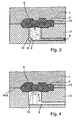
- the pressing tool in FIG. 3 is constructed analogously to that of FIG. 2, the difference is that the cavity 8 before the membrane contains a rubber container 12 in which again hydraulic oil 10 is located.
- the membrane 6 is at the bottom Stamp 2 with a screw not shown attached.
- On the rubber container 12 is connected via a Hydraulic pump pressure applied, which continues in this arrangement acts on the membrane.
- the advantage of this arrangement exists in that the hydraulic oil 10 is in the closed container 12 and so can not penetrate into the mold cavity 4. On a complex sealing of the membrane between the mold cavity 4 and the cavity 8 may be omitted.
- a further advantageous embodiment of the invention consists in a pressing tool according to Fig. 4.
- the pressing tool 4 is analogous to the pressing tools according to the figures. 1 to 3, but the cavity 8 contains instead of a Pressure medium, a piston 16.
- the membrane 6 is connected to the lower Stamp 2 welded.
- the piston 16 presses on the membrane 6, whereby this moves in the direction of mold cavity 4 and the Pressure on the SMC raw material passes.
Landscapes
- Engineering & Computer Science (AREA)
- Mechanical Engineering (AREA)
- Chemical & Material Sciences (AREA)
- Composite Materials (AREA)
- Casting Or Compression Moulding Of Plastics Or The Like (AREA)
- Moulds For Moulding Plastics Or The Like (AREA)
Abstract
Description
- Fig. 1
- ein Presswerkzeug mit einer Membran und einer hydraulischen Vorrichtung zur Bewegung der Membran, im geöffneten Zustand,
- Fig. 2
- ein Presswerkzeug nach Fig. 1 im geschlossenen Zustand,
- Fig. 3
- ein Presswerkzeug mit einem flexiblen Behälter zur Aufbringung eines hydraulischen Drucks auf eine Membran und
- Fig. 4
- ein Presswerkzeug mit einem Kolben zum Aufbringen eines Druckes auf eine Membran.
Claims (6)
- Formwerkzeug zur Herstellung von Kunststoffbauteilen (14), umfassend mindestens zwei Formstempel (1, 2), die in einem geschlossenen Zustand einen Formhohlraum (4) mit den Konturen des Kunststoffbauteils (14) bilden, wobei mindestens ein Formstempel (1, 2) mindestens eine Membran (6) aufweist, die durch Druckeinwirkung ein Volumen des Formhohlraums (4) verringert
dadurch gekennzeichnet,dass das Formwerkzeug als Presswerkzeug in der Art. ausgestaltet ist, dass formhohlraumfreie Bereiche (5a,b) der Formstempel (1, 2) plan aufeinander liegen,ein SMC-Halbzeug (3) umfassend Harz, Härter, Füllstoffe und Fasern in dem Formhohlraum (4) positioniert ist,wobei das SMC-Halbzeug (3) den Formhohlraum (4) in einem geschlossenen Zustand nahezu ausfüllt,wobei ein Volumenausgleich zwischen dem Formhohlraum (4) und dem SMC-Halbzeug (3) durch die Membran erfolgtund das Formwerkzeug zur Aushärtung des SMC-Halbzeugs temperierbar ist. - Formwerkzeug nach Anspruch 1,
dadurch gekennzeichnet, dass die Membran (6) aus Metall besteht. - Formwerkzeug nach Anspruch 1 oder 2,
dadurch gekennzeichnet, dass die mindestens eine Membran (6) in den Formhohlraum (4) .geschweißt oder geschraubt ist. - Formwerkzeug nach einem der Ansprüche 1 bis 3,
dadurch gekennzeichnet, dass die äußere Druckeinwirkung auf die Membran (6) durch Gasdruck oder Hydraulikdruck erfolgt. - Formwerkzeug nach Anspruch 4,
dadurch gekennzeichnet, dass ein Druckmedium (10) in einem flexiblen Behälter (12) eingeschlossen ist. - Formwerkzeug nach einem der Ansprüche 1 bis 3,
dadurch gekennzeichnet, dass die äußere Druckeinwirkung auf die Membran (6) durch einen Kolben (16) erfolgt.
Applications Claiming Priority (3)
| Application Number | Priority Date | Filing Date | Title |
|---|---|---|---|
| DE10129223A DE10129223A1 (de) | 2001-06-19 | 2001-06-19 | Formwerkzeug zur Herstellung eines Bauteils |
| DE10129223 | 2001-06-19 | ||
| PCT/EP2002/003910 WO2002102565A1 (de) | 2001-06-19 | 2002-04-09 | Formwerkzeug zur herstellung eines bauteils mit einer membran |
Publications (2)
| Publication Number | Publication Date |
|---|---|
| EP1401626A1 EP1401626A1 (de) | 2004-03-31 |
| EP1401626B1 true EP1401626B1 (de) | 2004-11-10 |
Family
ID=7688508
Family Applications (1)
| Application Number | Title | Priority Date | Filing Date |
|---|---|---|---|
| EP02780740A Expired - Lifetime EP1401626B1 (de) | 2001-06-19 | 2002-04-09 | Formwerkzeug zur herstellung eines bauteils mit einer membran |
Country Status (6)
| Country | Link |
|---|---|
| US (1) | US20040241273A1 (de) |
| EP (1) | EP1401626B1 (de) |
| JP (1) | JP4003005B2 (de) |
| DE (2) | DE10129223A1 (de) |
| ES (1) | ES2230520T3 (de) |
| WO (1) | WO2002102565A1 (de) |
Families Citing this family (6)
| Publication number | Priority date | Publication date | Assignee | Title |
|---|---|---|---|---|
| WO2006118442A1 (en) | 2005-05-03 | 2006-11-09 | Stork Sp Aerospace B.V. | Device for injecting a resin into at least one fibre layer of a fibre- reinforced product to be manufactured |
| DE102007023229A1 (de) * | 2007-05-18 | 2008-11-20 | Bayerische Motoren Werke Aktiengesellschaft | Vorrichtung und Verfahren zur Herstellung eines faserverstärkten Kunststoffbauteils |
| DE102019005916A1 (de) * | 2019-08-22 | 2021-02-25 | Siempelkamp Maschinen- Und Anlagenbau Gmbh | Verfahren zum Vorspannen der Membran einer Membranpresse und Presse zur Durchführung dieses Verfahrens |
| EP4017710B1 (de) * | 2019-08-22 | 2023-08-30 | Siempelkamp Maschinen- und Anlagenbau GmbH | Verfahren zur herstellung von formteilen aus faserverbund-werkstoff |
| DE102021000921A1 (de) * | 2021-02-22 | 2022-08-25 | Siempelkamp Maschinen- Und Anlagenbau Gmbh | Verfahren zur Herstellung von Formteilen |
| CN114347341B (zh) * | 2021-12-31 | 2024-04-09 | 佛山市国星光电股份有限公司 | 一种分立器件塑封装置及塑封方法 |
Family Cites Families (13)
| Publication number | Priority date | Publication date | Assignee | Title |
|---|---|---|---|---|
| SE333127B (sv) * | 1968-12-09 | 1971-03-08 | Saab Scania Ab | Anordning vid pressar foer formning av plataemnen medelst fluidumtryck |
| DE3117474A1 (de) * | 1981-05-02 | 1982-11-18 | Fa. Carl Zeiss, 7920 Heidenheim | Verfahren und vorrichtung zum herstellen von formteilen mit asphaerischen oberflaechen |
| JPS58223279A (ja) * | 1982-06-19 | 1983-12-24 | 株式会社フジクラ | ゴム・プラスチツクケ−ブルの接続方法 |
| US4708626A (en) * | 1985-03-14 | 1987-11-24 | Denki Kagaku Kogyo Kabushiki Kaisha | Mold assembly |
| JPH0761658B2 (ja) * | 1987-08-18 | 1995-07-05 | 金井 宏之 | 繊維強化樹脂製ホイ−ルの製造装置および製造法 |
| US4873044A (en) * | 1987-12-21 | 1989-10-10 | Shell Oil Company | Method and apparatus for reduction of mold cycle time |
| JPH0788903B2 (ja) * | 1989-05-25 | 1995-09-27 | 東洋ゴム工業株式会社 | 凹凸多溝構造を有するダイヤフラムの製造方法 |
| US5037599A (en) * | 1989-06-26 | 1991-08-06 | Basf Aktiengesellschaft | Single diaphragm forming of drapeable thermoplastic impregnated composite materials |
| DE4007331A1 (de) * | 1990-03-08 | 1991-09-12 | Phoenix Ag | Verfahren zum herstellen von bauteilen aus kunststoff und elastomeren |
| FR2694906B1 (fr) * | 1992-08-20 | 1994-09-23 | Acb | Presse pour le formage d'une pièce en matériau composite comportant des renforts fibreux dans une matrice en polymère. |
| JP3124906B2 (ja) * | 1995-05-26 | 2001-01-15 | 松下電工株式会社 | 熱硬化性樹脂の圧縮成形方法 |
| JP3284114B2 (ja) * | 1999-09-13 | 2002-05-20 | 株式会社リコー | 成形金型 |
| DE10000138A1 (de) * | 2000-01-04 | 2001-07-12 | Binder Technologie Ag Gams | Verfahren und Vorrichtung zur Herstellung von Formteilen |
-
2001
- 2001-06-19 DE DE10129223A patent/DE10129223A1/de not_active Ceased
-
2002
- 2002-04-09 DE DE50201524T patent/DE50201524D1/de not_active Expired - Fee Related
- 2002-04-09 WO PCT/EP2002/003910 patent/WO2002102565A1/de not_active Ceased
- 2002-04-09 US US10/481,273 patent/US20040241273A1/en not_active Abandoned
- 2002-04-09 JP JP2003505131A patent/JP4003005B2/ja not_active Expired - Fee Related
- 2002-04-09 ES ES02780740T patent/ES2230520T3/es not_active Expired - Lifetime
- 2002-04-09 EP EP02780740A patent/EP1401626B1/de not_active Expired - Lifetime
Also Published As
| Publication number | Publication date |
|---|---|
| ES2230520T3 (es) | 2005-05-01 |
| DE50201524D1 (de) | 2004-12-16 |
| EP1401626A1 (de) | 2004-03-31 |
| JP4003005B2 (ja) | 2007-11-07 |
| US20040241273A1 (en) | 2004-12-02 |
| WO2002102565A1 (de) | 2002-12-27 |
| DE10129223A1 (de) | 2003-01-23 |
| JP2004535313A (ja) | 2004-11-25 |
Similar Documents
| Publication | Publication Date | Title |
|---|---|---|
| DE69309185T2 (de) | Presse zum Formen eines Gegenstandes aus Verbundmaterial mit verstärkenden Fasern in einer Polimermatrix | |
| DE60013787T2 (de) | Vorrichtung zum formen von verbundgegenständen | |
| EP2419261B1 (de) | Werkzeug und verfahren zur herstellung eines verbundbauteils mittels einer zweiteiligen form und einer membrane | |
| DE3521507C2 (de) | ||
| DE102012023608B4 (de) | Verfahren und Vorrichtung zum Herstellen eines Formteils | |
| EP3397414A1 (de) | Verfahren zum herstellen von druckbehältern | |
| DE3727926C2 (de) | ||
| EP3365158A1 (de) | Verfahren zum herstellen eines bauteils aus einem faserverbundwerkstoff | |
| DE3689549T2 (de) | Formen und Beschichten in derselben Form. | |
| DE202015104700U1 (de) | Vorrichtung zur Herstellung von faserverstärkten Kunststoffteilen | |
| DE2534486A1 (de) | Verfahren und vorrichtung fuer die luftdruckverformung von thermoplastischen harzbahnenmaterialien | |
| EP3344446A1 (de) | Verfahren und vorrichtung zur herstellung von faserverstärkten kunststoffteilen | |
| EP1237694A2 (de) | Verfahren zur herstellung von formteilen sowie eine vorrichtung zur durchführung dieses verfahrens | |
| DE102012102594B4 (de) | Verfahren zum Herstellen von Formteilen aus Kunststoff | |
| DE10129223A1 (de) | Formwerkzeug zur Herstellung eines Bauteils | |
| DE1479117A1 (de) | Formpresse | |
| DE102012211693A1 (de) | Verfahren und Vorrichtung zum Formen von scharfen Formgebungslinien an Metallplatten | |
| WO1980002670A1 (en) | Mould for producing form castings of resin cast by reaction and utilisation of such mould | |
| DE3637544A1 (de) | Hydraulische schnellhubpresse | |
| DE1949983A1 (de) | Formpresse,insbesondere fuer Kunststoff | |
| EP3630479B1 (de) | Presse und verfahren zum herstellen des formteils | |
| EP0919356B1 (de) | Vakuumformmaschine zum Umformen von Formteilen | |
| DE4232610C2 (de) | Verfahren zur Herstellung von Laminattafeln und Einetagenplattenpresse für die Durchführung des Verfahrens | |
| DE3637545A1 (de) | Hydraulische schnellhubpresse | |
| DE19513444A1 (de) | Verfahren und Vorrichtung zum hydrostatischen Kaltverfahren von Blechen |
Legal Events
| Date | Code | Title | Description |
|---|---|---|---|
| PUAI | Public reference made under article 153(3) epc to a published international application that has entered the european phase |
Free format text: ORIGINAL CODE: 0009012 |
|
| 17P | Request for examination filed |
Effective date: 20031204 |
|
| AK | Designated contracting states |
Kind code of ref document: A1 Designated state(s): AT BE CH CY DE DK ES FI FR GB GR IE IT LI LU MC NL PT SE TR |
|
| GRAP | Despatch of communication of intention to grant a patent |
Free format text: ORIGINAL CODE: EPIDOSNIGR1 |
|
| RBV | Designated contracting states (corrected) |
Designated state(s): DE ES FR GB |
|
| GRAS | Grant fee paid |
Free format text: ORIGINAL CODE: EPIDOSNIGR3 |
|
| GRAA | (expected) grant |
Free format text: ORIGINAL CODE: 0009210 |
|
| AK | Designated contracting states |
Kind code of ref document: B1 Designated state(s): DE ES FR GB |
|
| PG25 | Lapsed in a contracting state [announced via postgrant information from national office to epo] |
Ref country code: GB Free format text: LAPSE BECAUSE OF FAILURE TO SUBMIT A TRANSLATION OF THE DESCRIPTION OR TO PAY THE FEE WITHIN THE PRESCRIBED TIME-LIMIT Effective date: 20041110 |
|
| REG | Reference to a national code |
Ref country code: GB Ref legal event code: FG4D Free format text: NOT ENGLISH |
|
| REF | Corresponds to: |
Ref document number: 50201524 Country of ref document: DE Date of ref document: 20041216 Kind code of ref document: P |
|
| PGFP | Annual fee paid to national office [announced via postgrant information from national office to epo] |
Ref country code: FR Payment date: 20050412 Year of fee payment: 4 |
|
| PGFP | Annual fee paid to national office [announced via postgrant information from national office to epo] |
Ref country code: ES Payment date: 20050418 Year of fee payment: 4 |
|
| REG | Reference to a national code |
Ref country code: ES Ref legal event code: FG2A Ref document number: 2230520 Country of ref document: ES Kind code of ref document: T3 |
|
| GBV | Gb: ep patent (uk) treated as always having been void in accordance with gb section 77(7)/1977 [no translation filed] |
Effective date: 20041110 |
|
| ET | Fr: translation filed | ||
| PLBE | No opposition filed within time limit |
Free format text: ORIGINAL CODE: 0009261 |
|
| STAA | Information on the status of an ep patent application or granted ep patent |
Free format text: STATUS: NO OPPOSITION FILED WITHIN TIME LIMIT |
|
| 26N | No opposition filed |
Effective date: 20050811 |
|
| PG25 | Lapsed in a contracting state [announced via postgrant information from national office to epo] |
Ref country code: ES Free format text: LAPSE BECAUSE OF NON-PAYMENT OF DUE FEES Effective date: 20060410 |
|
| REG | Reference to a national code |
Ref country code: FR Ref legal event code: ST Effective date: 20061230 |
|
| REG | Reference to a national code |
Ref country code: ES Ref legal event code: FD2A Effective date: 20060410 |
|
| PG25 | Lapsed in a contracting state [announced via postgrant information from national office to epo] |
Ref country code: FR Free format text: LAPSE BECAUSE OF NON-PAYMENT OF DUE FEES Effective date: 20060502 |
|
| PGFP | Annual fee paid to national office [announced via postgrant information from national office to epo] |
Ref country code: DE Payment date: 20090422 Year of fee payment: 8 |
|
| PG25 | Lapsed in a contracting state [announced via postgrant information from national office to epo] |
Ref country code: DE Free format text: LAPSE BECAUSE OF NON-PAYMENT OF DUE FEES Effective date: 20101103 |