EP1401136B1 - Vorrichtung zur Verarbeitung von Signalen welche durch Übertragungsfehler beeinträchtigt sind - Google Patents
Vorrichtung zur Verarbeitung von Signalen welche durch Übertragungsfehler beeinträchtigt sind Download PDFInfo
- Publication number
- EP1401136B1 EP1401136B1 EP03026331A EP03026331A EP1401136B1 EP 1401136 B1 EP1401136 B1 EP 1401136B1 EP 03026331 A EP03026331 A EP 03026331A EP 03026331 A EP03026331 A EP 03026331A EP 1401136 B1 EP1401136 B1 EP 1401136B1
- Authority
- EP
- European Patent Office
- Prior art keywords
- digital signals
- situation
- signal
- errors
- switch over
- Prior art date
- Legal status (The legal status is an assumption and is not a legal conclusion. Google has not performed a legal analysis and makes no representation as to the accuracy of the status listed.)
- Expired - Lifetime
Links
- 230000005540 biological transmission Effects 0.000 title claims description 12
- 238000000034 method Methods 0.000 claims description 9
- 230000003044 adaptive effect Effects 0.000 claims description 2
- 230000008569 process Effects 0.000 claims 2
- 239000000523 sample Substances 0.000 description 4
- 238000010586 diagram Methods 0.000 description 3
- 230000002035 prolonged effect Effects 0.000 description 2
- 230000000694 effects Effects 0.000 description 1
- 230000007257 malfunction Effects 0.000 description 1
- 238000012986 modification Methods 0.000 description 1
- 230000004048 modification Effects 0.000 description 1
- 230000011664 signaling Effects 0.000 description 1
- 230000003595 spectral effect Effects 0.000 description 1
Images
Classifications
-
- H—ELECTRICITY
- H04—ELECTRIC COMMUNICATION TECHNIQUE
- H04L—TRANSMISSION OF DIGITAL INFORMATION, e.g. TELEGRAPHIC COMMUNICATION
- H04L1/00—Arrangements for detecting or preventing errors in the information received
Definitions
- the present invention relates to a system for processing analog signals transmitted in the form of digital signals, being temporarily affected by transmission errors, as described In the preamble of claim 1.
- One of the simplest methods of eliminating transmission errors is to silence the channel as long as noise is present.
- Another method used is to repeat the last received correct value. Although these methods are effective, the output is either missing or not compensated, hence other types of disturbances are introduced into the channel and a rough reconstruction of the original signal is anyway carried out.
- EP-B-0 103 385 discloses a system in which the last valid value is stored, the first and second derivatives are computed and the estimated slope of the signal affected by error is reconstructed from these.
- a method more effective than the previous ones uses a technique of interpolating between the valid samples respectively preceding and following the error-affected one, to obtain the interpolated value.
- the system of D1 and D2 comprising: a terminal to which a validity signal of the input digital signals is fed; switching means for a first switch over from a situation of normal operation to a situation of operation in presence of errors and for a second switch over from the situation of operation in presence of errors to the situation of normal operation; and computing means for determining computed samples of said digital signals using information relative to said digital signals.
- the main object of the present invention is then to provide a system for making the effects of the transmission error sequences imperceptible and avoiding discontinuities when switching back from an "erroneous" state of operation to a "normal" state of operation.
- the system is characterized in that said computing means estimates the value of said computed samples by continually predicting expected values of said digital signals; in that, in response to said first switch over, said computed samples are provided as an output signal; and in that the system further comprises means, connected to said switching means, responsive to said input digital signals and to said output signal and generating a filtered signal used to eliminate a discontinuity in said output signal during said second switch over from the situation of operation in the presence of errors to the situation of normal operation.
- the system is characterized in that said computing means determines the value of said computed samples by continually predicting expected values of said digital signals; in that, in response to said second switch over, said computed samples are provided as an output signal; and in that the system further comprises means, connected to said switching means, responsive to said input digital signals and producing a predicted signal used to eliminate a discontinuity in said output signal during said second switch over from the situation of operation in the presence of errors to the situation of normal operation.
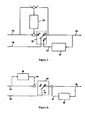
- Fig. 1 shows: a switch 10 with terminals 11, 12, 13; a terminal to which an input signal 14 is fed; a terminal to which a validity signal 15 of the input signal 14 is fed, that drives switch 10; a terminal to which an output signal 16 is fed and which is connected to terminal 13 of switch 10; a terminal to which a predicted signal 17 is fed; a predictor 18 having the output signal 16 as an input and the predicted signal 17 as an output, connected to terminal 12 of the switch 10; a filter 19 whose input is fed with the difference between the input signal 14 and the output signal 16 and whose output, summed to the input signal 14, is fed to terminal 11 of switch 10.
- signal 14 is received in the form of numeric sample sequences and signal 15 is a signalling of the validity of the samples themselves, e.g., the output of a generic system detects temporary malfunctions on the channel; assume further that occasionally the samples of signal 14 can be affected by errors and, therefore, useless. In order to replace these useless samples it is proposed here to use a predictor 18 well known from the literature and described later on.
- switch 10 switches over the predicted signal 17. After a certain time interval the received samples will be valid again, hence switch 10 shall change over from predicted samples to valid samples.
- the use of the predictor, as herein described, solves the problem in question, but it may happen that the last change-over does not take place in the best possible way.
- the filter 19 is used.
- this filter is composed of a delay cell followed by a multiplication by a positive constant less than one.
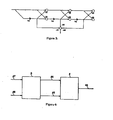
- a switch 20 with terminals 21, 22 and 23, of which terminal 22 is disconnected; a terminal to which an input signal 24 is fed; a terminal to which a validity signal 25 of the input signal 24 is fed, that drives the switch 20; a terminal to which an output signal 26 is fed; a terminal to which a first predicted signal 27 is fed; a signal to which a second prediction signal 30 is fed; a first predictor 28 having the output signal 26 as an input and the first predicted signal 27 as an output which, summed to signal from terminal 23 of switch 20, is connected to the output signal 26; a second predictor 29 having signal 24 as an input and the second predicted signal 30 as an output which, subtracted from input signal 24, is connected to terminal 21 of the switch.
- Predictors 28 and 29 are of the same type as predictor 18 of Fig. 1 .
- Fig. 3 there is shown the schematic representation of a possible realization of the above-mentioned predictors 18, 28, 29.
- This signal is obtained through the weighted average of the last input samples. Naturally the weights change slowly following the statistical characteristic of the signal.
- block 4 represents the system as described above and may consist of either the system shown in Fig. 1 or the one shown in Fig. 2 , and block 3 represents a circuit arrangement suitable for processing individual errors.
- This block is not indispensable, but the overall features are improved.
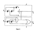
- Block 3 could be constituted by any circuit arrangement known in the literature for processing individual errors, an example thereof being represented in Fig. 5 as used by the inventors in this circumstance. It consists mainly of two blocks:
Landscapes
- Engineering & Computer Science (AREA)
- Computer Networks & Wireless Communication (AREA)
- Signal Processing (AREA)
- Detection And Prevention Of Errors In Transmission (AREA)
- Compression, Expansion, Code Conversion, And Decoders (AREA)
- Noise Elimination (AREA)
- Analogue/Digital Conversion (AREA)
Claims (8)
- System zur Verarbeitung von in der Form von digitalen Signalen (14, 24) übertragenen analogen Signalen, wobei die besagten digitalen Signale zeitweise durch Übertragungsfehler beeinträchtigt sind, wobei das besagte System umfasst:Ein Endgerät, in welches ein Gültigkeitssignal (15, 25) der eingegebenen digitalen Signale (14, 24) eingespeist wird;Schaltmittel (10, 20) für ein erstes Umschalten von einem normalen Betriebszustand zu einem fehlerbehafteten Betriebszustand, und für ein zweites Umschalten von dem fehlerbehafteten Betriebszustand zu dem normalen Betriebszustand;Rechenmittel (18) zum Bestimmen von berechneten Abtastwerten der besagten digitalen Signale (14, 24) unter Verwendung von auf die besagten digitalen Signale (14, 24) bezogenen Informationen;dadurch gekennzeichnet, dass das besagte Rechenmittel dazu ausgelegt ist, den Wert der besagten berechneten Abtastwerte durch kontinuierliches Vorhersagen von erwarteten Werten der besagten digitalen Signale (14, 24) zu schätzen;
dass, in Reaktion auf das besagte erste Umschalten, die besagten berechneten Abtastwerte als ein Ausgangssignal bereitgestellt werden;
und dass das System weiterhin ein an das besagte Schaltmittel angeschlossenes Mittel (19, 16a) umfasst, welches auf die besagten eingegebenen digitalen Signale und auf das besagte Eingangssignal anspricht und ein gefiltertes Signal erzeugt, welches verwendet wird, um während des besagten zweiten Umschaltens von dem fehlerbehafteten Betriebszustand zu dem normalen Betriebszustand eine Diskontinuität in dem besagten Ausgangssignal zu eliminieren. - System zum Verarbeiten von in der Form von digitalen Signalen (14, 24) übertragenen analogen Signalen, wobei die besagten digitalen Signale zeitweise durch Übertragungsfehler beeinträchtigt sind, wobei das besagte System umfasst:Ein Endgerät, in welches ein Gültigkeitssignal (15, 25) der eingegebenen digitalen Signale (14, 24) eingespeist wird;Schaltmittel (10, 20) für ein erstes Umschalten von einem normalen Betriebszustand zu einem fehlerbehafteten Betriebszustand, und für ein zweites Umschalten von dem fehlerbehafteten Betriebszustand zu dem normalen Betriebszustand;Rechenmittel (28) zum Bestimmen von berechneten Abtastwerten der besagten digitalen Signale (14, 24) unter Verwendung von Informationen, die für den Wert der besagten digitalen Signale (14, 24) indikativ sind;dadurch gekennzeichnet, dass das besagte Rechenmittel dazu ausgelegt ist, den Wert der besagten berechneten Abtastwerte durch kontinuierliches Vorhersagen von erwarteten Werten der besagten digitalen Signale (14, 24) zu bestimmen;
dass, in Reaktion auf das besagte erste Umschalten, die besagten berechneten Abtastwerte als ein Ausgangssignal bereitgestellt werden;
und dass das System weiterhin ein an das besagte Schaltmittel angeschlossenes Mittel (29) umfasst, welches auf die besagten eingegebenen digitalen Signale anspricht und ein vorhergesagtes Signal erzeugt, welches verwendet wird, um während des besagten zweiten Umschaltens von dem fehlerbehafteten Betriebszustand zu dem normalen Betriebszustand eine Diskontinuität in dem besagten Ausgangssignal zu eliminieren. - System nach Anspruch 1 oder 2, dadurch gekennzeichnet, dass das Rechenmittel ein Prädiktor (18, 28) ist.
- System nach Anspruch 3, dadurch gekennzeichnet, dass der Prädiktor (18, 28) ein adaptiver linearer Prädiktor ist.
- System nach Anspruch 1 oder 2, dadurch gekennzeichnet, dass das besagte Schaltmittel (10, 20) von dem Gültigkeitssignal (15, 25), welches für die Gültigkeit der besagten digitalen Signale (14, 24) indikativ ist, angesteuert wird.
- System nach Anspruch 1 oder 2, dadurch gekennzeichnet, dass ein Diskontinuitäts-Messsignal gefiltert (19) und mit den besagten digitalen Signalen (14) summiert wird, um ein summiertes Signal an das besagte Schaltmittel bereitzustellen, wobei das besagte Schaltmittel das besagte Ausgangssignal (16) ohne die Diskontinuität bereitstellt, und wobei das besagte Diskontinuitäts-Messsignal eine Differenz zwischen den besagten digitalen Signalen (14) und dem besagten Ausgangssignal (16) ist.
- System nach Anspruch 1 oder 2, welchem eine Schaltungsanordnung (3) für die Signalverarbeitung vorgeschaltet ist, dadurch gekennzeichnet, dass die Schaltungsanordnung einzelne Übertragungsfehler verarbeitet.
- System nach Anspruch 7, dadurch gekennzeichnet, dass die besagte Schaltungsanordnung dazu ausgelegt ist, einen entsprechenden der besagten einzelnen Übertragungsfehler durch Erstellen einer linearen Interpolation zwischen einem ersten Abtastwert, welcher dem entsprechenden der besagten einzelnen Übertragungsfehler vorausgeht, und einem zweiten Abtastwert, welcher dem entsprechenden der besagten einzelnen Übertragungsfehler folgt, zu verarbeiten.
Applications Claiming Priority (3)
| Application Number | Priority Date | Filing Date | Title |
|---|---|---|---|
| ITMI930845 | 1993-04-29 | ||
| ITMI930845A IT1272418B (it) | 1993-04-29 | 1993-04-29 | Sistema per il trattamento di segnali affetti da errori di trasmissione |
| EP94105924A EP0622921A3 (de) | 1993-04-29 | 1994-04-16 | System zur Verarbeitung von Signalen welche durch Übertragungsfehler beeinträchtigt sind. |
Related Parent Applications (2)
| Application Number | Title | Priority Date | Filing Date |
|---|---|---|---|
| EP94105924.8 Division | 1994-04-16 | ||
| EP94105924A Division EP0622921A3 (de) | 1993-04-29 | 1994-04-16 | System zur Verarbeitung von Signalen welche durch Übertragungsfehler beeinträchtigt sind. |
Publications (3)
| Publication Number | Publication Date |
|---|---|
| EP1401136A2 EP1401136A2 (de) | 2004-03-24 |
| EP1401136A3 EP1401136A3 (de) | 2004-03-31 |
| EP1401136B1 true EP1401136B1 (de) | 2013-03-27 |
Family
ID=11365933
Family Applications (2)
| Application Number | Title | Priority Date | Filing Date |
|---|---|---|---|
| EP03026331A Expired - Lifetime EP1401136B1 (de) | 1993-04-29 | 1994-04-16 | Vorrichtung zur Verarbeitung von Signalen welche durch Übertragungsfehler beeinträchtigt sind |
| EP94105924A Withdrawn EP0622921A3 (de) | 1993-04-29 | 1994-04-16 | System zur Verarbeitung von Signalen welche durch Übertragungsfehler beeinträchtigt sind. |
Family Applications After (1)
| Application Number | Title | Priority Date | Filing Date |
|---|---|---|---|
| EP94105924A Withdrawn EP0622921A3 (de) | 1993-04-29 | 1994-04-16 | System zur Verarbeitung von Signalen welche durch Übertragungsfehler beeinträchtigt sind. |
Country Status (3)
| Country | Link |
|---|---|
| US (1) | US5684840A (de) |
| EP (2) | EP1401136B1 (de) |
| IT (1) | IT1272418B (de) |
Families Citing this family (1)
| Publication number | Priority date | Publication date | Assignee | Title |
|---|---|---|---|---|
| US5986826A (en) * | 1996-12-17 | 1999-11-16 | Minolta Co., Ltd. | Drive device using electromechanical conversion element |
Family Cites Families (17)
| Publication number | Priority date | Publication date | Assignee | Title |
|---|---|---|---|---|
| US4243935A (en) * | 1979-05-18 | 1981-01-06 | The United States Of America As Represented By The Secretary Of The Navy | Adaptive detector |
| GB2081913B (en) * | 1979-12-14 | 1983-08-03 | Hewlett Packard Ltd | Noise margin measurement and error probability prediction |
| US4458362A (en) * | 1982-05-13 | 1984-07-03 | Teledyne Industries, Inc. | Automatic time domain equalization of audio signals |
| EP0103385B1 (de) | 1982-07-30 | 1987-04-08 | Victor Company Of Japan, Limited | Schaltungsanordnung zum Wiederherstellen von durch Störgeräusch beeinflussten Signalen |
| DE3311911A1 (de) | 1983-03-31 | 1984-10-04 | Siemens AG, 1000 Berlin und 8000 München | Verfahren und schaltungsanordnung zur bildfehlerkorrektur |
| JPS6035838A (ja) | 1983-08-08 | 1985-02-23 | Victor Co Of Japan Ltd | パルス性雑音の低減装置 |
| DE3446529A1 (de) * | 1984-12-20 | 1986-07-03 | Blaupunkt-Werke Gmbh, 3200 Hildesheim | Verfahren zur stoerverminderung in einer rundfunk-empfangsanlage |
| US4969192A (en) * | 1987-04-06 | 1990-11-06 | Voicecraft, Inc. | Vector adaptive predictive coder for speech and audio |
| US4907248A (en) * | 1987-09-22 | 1990-03-06 | Zenith Electronics Corporation | Error correction for digital signal transmission |
| US5161185A (en) * | 1989-06-21 | 1992-11-03 | Texas Instruments Incorporated | Method and apparatus for reducing noise in a digital voltage signal |
| DE69220255T2 (de) * | 1991-01-18 | 1997-11-20 | Nippon Electric Co | Schaltung zur Unterdrückung von weissem Rauschen |
| CA2067669C (en) * | 1991-04-30 | 1997-10-28 | Akihisa Ushirokawa | Method and apparatus of estimating data sequence transmitted using viterbi algorithm |
| US5345452A (en) * | 1991-05-29 | 1994-09-06 | Nec Corporation | Adaptive equalizer for removing nonlinear distortions from digital signals |
| US5369791A (en) * | 1992-05-22 | 1994-11-29 | Advanced Micro Devices, Inc. | Apparatus and method for discriminating and suppressing noise within an incoming signal |
| US5309443A (en) * | 1992-06-04 | 1994-05-03 | Motorola, Inc. | Dynamic muting method for ADPCM coded speech |
| US5383202A (en) * | 1992-11-25 | 1995-01-17 | Motorola, Inc. | Simplified method of attenuation of logarithmically coded digital signals |
| US5465404A (en) * | 1993-01-29 | 1995-11-07 | Motorola, Inc. | Communications receiver with an adaptive squelch system |
-
1993
- 1993-04-29 IT ITMI930845A patent/IT1272418B/it active IP Right Grant
-
1994
- 1994-04-16 EP EP03026331A patent/EP1401136B1/de not_active Expired - Lifetime
- 1994-04-16 EP EP94105924A patent/EP0622921A3/de not_active Withdrawn
- 1994-04-18 US US08/229,362 patent/US5684840A/en not_active Expired - Lifetime
Also Published As
| Publication number | Publication date |
|---|---|
| IT1272418B (it) | 1997-06-23 |
| ITMI930845A1 (it) | 1994-10-29 |
| ITMI930845A0 (it) | 1993-04-29 |
| EP1401136A2 (de) | 2004-03-24 |
| EP1401136A3 (de) | 2004-03-31 |
| EP0622921A3 (de) | 1995-08-02 |
| EP0622921A2 (de) | 1994-11-02 |
| US5684840A (en) | 1997-11-04 |
Similar Documents
| Publication | Publication Date | Title |
|---|---|---|
| EP0116975B1 (de) | Sprachangepasstes prädiktives Kodierungssystem | |
| US4719642A (en) | Error detection and concealment using predicted signal values | |
| US4667233A (en) | Apparatus for discriminating a moving region and a stationary region in a video signal | |
| US4587620A (en) | Noise elimination device | |
| US4866510A (en) | Digital video encoder | |
| CA2067669A1 (en) | Method and apparatus of estimating data sequence transmitted using viterbi algorithm | |
| CA2057139A1 (en) | Method to evaluate the pitch and voicing of the speech signal in vocoders with very slow bit rates | |
| US4224689A (en) | Apparatus for smoothing transmission errors | |
| US5495526A (en) | Tone-detection method for detecting at least one tone in a dual-tone multifrequency signal, call-progress method using the same | |
| KR880010581A (ko) | 예측 부호화 장치 및 방법 | |
| KR950014914B1 (ko) | 블럭화 전송 신호의 디코드 장치 | |
| CA1340064C (en) | Signal processing apparatus with dual parallel a/d and d/a converters | |
| US5684840A (en) | System for eliminating the affected by transmission errors in a digital stream | |
| US5265219A (en) | Speech encoder using a soft interpolation decision for spectral parameters | |
| EP0547460B1 (de) | Verfahren und System zum Anpassen des Auffrischungszyklus an die Komplexität des Bildes | |
| JP2655485B2 (ja) | 音声セル符号化装置 | |
| KR100329875B1 (ko) | 신호샘플들을연속적으로전송하는전송시스템,이시스템에사용되는전송기,수신기,코더,디코더,및신호샘플을재구성하는보간수단,신호샘플에용장성을부가하는방법,및신호샘플을재구성하는방법 | |
| JP3583550B2 (ja) | 補間装置 | |
| JPS56109085A (en) | Decoder for adaptive prediction for picture signal | |
| CA1308474C (en) | Arrangement for dpcm-coding of video signals | |
| SU1220133A1 (ru) | Многоканальна адаптивна цифрова система св зи | |
| SU1656574A1 (ru) | Устройство дл сжати информации | |
| SU932641A1 (ru) | Устройство групповой тактовой синхронизации | |
| JPH113485A (ja) | テレコン、テレメ−タ用デ−タ伝送方式 | |
| SU886262A1 (ru) | Устройство адаптивной коррекции межсимвольных искажений |
Legal Events
| Date | Code | Title | Description |
|---|---|---|---|
| PUAI | Public reference made under article 153(3) epc to a published international application that has entered the european phase |
Free format text: ORIGINAL CODE: 0009012 |
|
| PUAL | Search report despatched |
Free format text: ORIGINAL CODE: 0009013 |
|
| 17P | Request for examination filed |
Effective date: 20031128 |
|
| AC | Divisional application: reference to earlier application |
Ref document number: 0622921 Country of ref document: EP Kind code of ref document: P |
|
| AK | Designated contracting states |
Kind code of ref document: A2 Designated state(s): DE FR GB |
|
| AK | Designated contracting states |
Kind code of ref document: A3 Designated state(s): DE FR GB |
|
| AKX | Designation fees paid |
Designated state(s): DE FR GB |
|
| RAP1 | Party data changed (applicant data changed or rights of an application transferred) |
Owner name: ALCATEL LUCENT |
|
| 17Q | First examination report despatched |
Effective date: 20091215 |
|
| RAP1 | Party data changed (applicant data changed or rights of an application transferred) |
Owner name: ALCATEL LUCENT |
|
| GRAP | Despatch of communication of intention to grant a patent |
Free format text: ORIGINAL CODE: EPIDOSNIGR1 |
|
| GRAS | Grant fee paid |
Free format text: ORIGINAL CODE: EPIDOSNIGR3 |
|
| GRAA | (expected) grant |
Free format text: ORIGINAL CODE: 0009210 |
|
| AC | Divisional application: reference to earlier application |
Ref document number: 0622921 Country of ref document: EP Kind code of ref document: P |
|
| AK | Designated contracting states |
Kind code of ref document: B1 Designated state(s): DE FR GB |
|
| REG | Reference to a national code |
Ref country code: GB Ref legal event code: FG4D |
|
| REG | Reference to a national code |
Ref country code: DE Ref legal event code: R096 Ref document number: 69435390 Country of ref document: DE Effective date: 20130523 |
|
| PGFP | Annual fee paid to national office [announced via postgrant information from national office to epo] |
Ref country code: DE Payment date: 20130419 Year of fee payment: 20 Ref country code: GB Payment date: 20130418 Year of fee payment: 20 |
|
| REG | Reference to a national code |
Ref country code: GB Ref legal event code: 732E Free format text: REGISTERED BETWEEN 20130801 AND 20130807 |
|
| PGFP | Annual fee paid to national office [announced via postgrant information from national office to epo] |
Ref country code: FR Payment date: 20130515 Year of fee payment: 20 |
|
| REG | Reference to a national code |
Ref country code: FR Ref legal event code: GC Effective date: 20131120 |
|
| PLBE | No opposition filed within time limit |
Free format text: ORIGINAL CODE: 0009261 |
|
| STAA | Information on the status of an ep patent application or granted ep patent |
Free format text: STATUS: NO OPPOSITION FILED WITHIN TIME LIMIT |
|
| 26N | No opposition filed |
Effective date: 20140103 |
|
| REG | Reference to a national code |
Ref country code: DE Ref legal event code: R097 Ref document number: 69435390 Country of ref document: DE Effective date: 20140103 |
|
| REG | Reference to a national code |
Ref country code: DE Ref legal event code: R071 Ref document number: 69435390 Country of ref document: DE |
|
| REG | Reference to a national code |
Ref country code: DE Ref legal event code: R071 Ref document number: 69435390 Country of ref document: DE |
|
| REG | Reference to a national code |
Ref country code: GB Ref legal event code: PE20 Expiry date: 20140415 |
|
| PG25 | Lapsed in a contracting state [announced via postgrant information from national office to epo] |
Ref country code: GB Free format text: LAPSE BECAUSE OF EXPIRATION OF PROTECTION Effective date: 20140415 |
|
| PG25 | Lapsed in a contracting state [announced via postgrant information from national office to epo] |
Ref country code: DE Free format text: LAPSE BECAUSE OF EXPIRATION OF PROTECTION Effective date: 20140417 |
|
| REG | Reference to a national code |
Ref country code: FR Ref legal event code: RG Effective date: 20141016 |