EP1401049A1 - Halterung für eine Satellitenantenne - Google Patents
Halterung für eine Satellitenantenne Download PDFInfo
- Publication number
- EP1401049A1 EP1401049A1 EP02292308A EP02292308A EP1401049A1 EP 1401049 A1 EP1401049 A1 EP 1401049A1 EP 02292308 A EP02292308 A EP 02292308A EP 02292308 A EP02292308 A EP 02292308A EP 1401049 A1 EP1401049 A1 EP 1401049A1
- Authority
- EP
- European Patent Office
- Prior art keywords
- support member
- satellite antenna
- antenna holder
- axis
- adjustable support
- Prior art date
- Legal status (The legal status is an assumption and is not a legal conclusion. Google has not performed a legal analysis and makes no representation as to the accuracy of the status listed.)
- Granted
Links
Images


Classifications
-
- H—ELECTRICITY
- H01—ELECTRIC ELEMENTS
- H01Q—ANTENNAS, i.e. RADIO AERIALS
- H01Q3/00—Arrangements for changing or varying the orientation or the shape of the directional pattern of the waves radiated from an antenna or antenna system
- H01Q3/02—Arrangements for changing or varying the orientation or the shape of the directional pattern of the waves radiated from an antenna or antenna system using mechanical movement of antenna or antenna system as a whole
-
- H—ELECTRICITY
- H01—ELECTRIC ELEMENTS
- H01Q—ANTENNAS, i.e. RADIO AERIALS
- H01Q1/00—Details of, or arrangements associated with, antennas
- H01Q1/12—Supports; Mounting means
- H01Q1/125—Means for positioning
Definitions
- Satellite antennas in particular parabolic antennas popularly referred to as "satellite dishes” have come into widespread use with the advent of satellite-based television. Such satellite dishes are known to require careful alignment in order to achieve a good reception performance.
- simple antenna holders In order to allow for elevation and azimuth alignment of such antennas, in particular of antennas for private household use, simple antenna holders have been designed in which e.g. a ball-and-socket joint ensured to degrees of rotational freedom. In an unlocked state of this joint, the dish was pivoted freehandedly until an appropriate alignment was found, and then the joint was locked in order to fix the dish in this alignment.
- the alignment of the satellite antenna with respect to the satellite is much more critical than for downlink. This is because the receiving characteristic of the satellite dish on earth, being very narrow and aimed at the satellite, receives very little noise besides the signal from the satellite, whereas a satellite antenna that must be able to receive uplink signals from numerous satellite dishes at various places on earth is exposed to a much higher level of noise. Therefore, it is expected that for bi-directional applications, earthborn satellite antennas will have to be aligned with an accuracy of approximately 0.1 degrees. This is a level of precision which is not reliably achieved with the conventional satellite dish holders described above.
- the object of the present invention is to provide a simple and economical satellite holder that can be aligned quickly and with a high degree of precision.
- an adjustable satellite antenna holder comprising a first base member, a first coarsely adjustable support member pivotable about a first axis with respect to the first base member and a first finely adjustable support member pivotable about an axis parallel to said first axis with respect to the first coarsely adjustable support member.
- the first base member of the antenna holder When the first base member of the antenna holder is mounted on an appropriate substructure and the satellite antenna is mounted to its first finely adjustable support member, a quick and rough adjustment can simply be done by turning the first coarsely adjustable support member until a downlink signal from a desired satellite is received, and then using the finely adjustable support member for a fine alignment.
- the coarsely adjustable support member may simply be a joint rotated by hand, as in the prior art, the finely adjustable support member will preferably comprise an adjusting actuator by which small rotations in the range of 0.1 to 1 degree can be reliably and reproducibly driven.
- a two-stage construction may be used in which the first base member and support members are for adjustment of one rotational degree of freedom, and a second stage comprising a second base member, a second coarsely adjustable support member and a second finely adjustable support member is provided for the second rotational degree of freedom.
- the first base member is rigidly coupled to the second finely adjustable support member; in particular, they may be formed by a unitary element.
- the second support member need not be integrated into a single device together with the other members; it may e.g. be a pole or another type of appropriate substructure to which the satellite antenna holder is mounted, a coarse adjustment between the pole and the second coarsely adjustable support member being done at mounting time.
- the adjusting actuator should preferably be designed so as to lock the support members coupled by it relative to each other when it is not driven.
- Such an actuator may simply comprise a screw and a nut that can be rotated with respect to each other, a pneumatic or hydraulic piston, a motorized translation stage, etc.
- the actuator comprises a screw mounted to one of said support members and a nut rotatably mounted to the other support member and engaging the screw.
- the screw is rigidly held at said one support member and the nut is coupled to a cross-bar that engages said other support member and is gradually displaceable therein with respect to the pivoting axis.
- the screw may be gradually displaceably engaged with said one support member, and the other support member to which the nut is rotatably mounted comprises guiding means for guiding the screw in its longitudinal direction.
- the actuator is also formed of a screw, and this screw has a circumferential profile, preferably a circumferential groove near the head of the screw, which is rotatably engaged with one of said support members, the threaded portion of the screw engaging a threaded bore of said other support member.
- the portion of said one support member engaging the groove preferably has a circular cross section, so that it can freely tilt within the groove when the support members are pivoted with respect to each other.
- the screw should be equipped with a locking nut for locking the screw once a properly aligned position has been found.
- the actuator comprises two screws mounted in threaded bores of one of said support member in such a way that the tips of these screws face each other, and a trunnion of said other support member extending between the tips.
- the two support members may be freely rotated with respect to each other by hand, until the trunnion hits one of the two tips.
- a fine adjustment can be carried out by reducing the space between the tips to a minimum and rotating both screws and synchronism, so that one tip pushes the trunnion while simultaneously, the other tips recedes.
- This type of actuator is particularly suitable for azimuth adjustment.
- the pitch of the screw(s) such that one turn of the screw(s) corresponds to a rotation of the finely adjustable support member of less than 0.5°.
- the rotation of the finely adjustable support member per turn of the screw should be at least 0.1 °.
- a very advantageous locking means is an eccentric mounted on a shaft defining the axis of rotation, the eccentric being pivotable between a locking position in which it urges said members into a frictional engagement and an unlocking position in which said frictional engagement is released. Since the eccentric is mounted close to the axis of rotation, any torque it might exercise when locking is very small. In particular, if the eccentric comes into contact with one of said members of both sides of the shaft, frictional forces exercised on these two sides tend to compensate each other.
- a base member may be provided with a circular slot centred around its axis of rotation, and the coarsely adjustable support member that is pivotable around this axis of rotation has a threaded portion extending through the slot which may be fixed to the slot using a nut.
- This type of fixing means is particularly appropriate for fixing when a coarse adjustment for one degree of freedom has been carried out and before the fine adjustment is begun. A slight pivoting movement of the coarsely adjustable support member which may be caused by fixing the screws may afterwards be compensated during fine adjustment.
- the holder shown in Fig. 1 comprises a first finely adjustable support member 1 which is approximately in the shape of the letter L. It has an approximately vertical branch 10 and an approximately horizontal branch 11. A slot 12 extends through all of branch 10 and most of branch 11. A cylindrical rod 13 extends through a bore which is formed at the angle between branches 10, 11 of first finely adjustable support member 1 and is held in a first base member 3.
- a first roughly adjustable support member 2 is also rotatably mounted to the rod 13.
- the roughly adjustable support member 2 is formed of a rod 20 of rectangular cross section bearing two crossbars 21 and 22. As is best seen in Fig. 2, the crossbar 21 has two upturned end portions 23 in which holes are formed through which the cylindrical rod 13 rotatably extends.
- Fig. 2 only a left hand portion of the first finely adjustable support member 1 is shown, the portion to the right of slot 12 is not represented in order to allow a view of adjusting means 26 to 29 that will be explained in detail below.
- the other crossbar 22 has threaded end portions 24 that extend through slots 30 formed in vertical side wings 31 of first base member 3 and may be fixed to the base member 3 in a given position by means of nuts 25.
- the slots 30 are in the shape of circle sectors that extend concentrically around the cylindrical rod 13.
- a threaded bolt 26 extends perpendicularly from the surface of the rod 20 into the slot 12 of branch 11. It extends through a bore (not shown) of rod 20 and is fixed to the rod 20 by means of locking nuts at the upper and lower sides of rod 20, only the upper one of which is shown in the Fig.
- the threaded bolt 26 bears a knurled nut 27 held in a cage 28.
- the cage 28 has openings through which the nut 27 can be rotated by a user's fingers, whereby the cage 28 is displaced up and down along the threaded bolt 26.
- the cage 28 has two laterally extending arms 29 that engage slits 14 symmetrically formed in the left-hand and right-hand portions of branch 11 of first finely adjustable support member 1.
- the members 1, 2, 3 form an elevation adjusting mechanism of the antenna holder. Adjustment is carried out by first roughly setting the orientation of roughly adjustable support member 2 with respect to base member 3. This can be done by tilting member 2 by hand until a weak satellite signal is received by an antenna mounted on branch 10, or by setting the angle between base member 3 and roughly adjustable support member 2 to a predefined value, for example by inserting a template between the rod 20 and a base plate 32 of support member 3, adapting the angle between the two to the template and fixing the roughly adjustable support member 2 using the nuts 25.
- a fine adjustment is then carried out by setting the position of finely adjustable support member 1 with respect to roughly adjustable support member 2 by rotating the nut 27 until optimal receiving conditions are achieved.
- the pitch of threaded bolt 26 is set such that the bolt 26 is self-locking, i.e. that pressure exercised on the support members will not cause the bolt 26 to rotate.
- the pitch should be such that one turn of the nut 27 corresponds to a rotation of the finely adjustable support member 1 of approximately 0,1° to 0,5° if a beam opening angle of 0,1° is assumed for the satellite at which the antenna is directed.
- the base plate 32 forms a second finely adjustable support member for an azimuth adjusting mechanism.
- This mechanism further comprises a pole 5 forming a second base member and a pole adaptor 4 forming a second roughly adjustable support member.
- the pole 5 is cylindrical in cross section, and the pole adaptor 4 has a mounting socket which is not shown in detail in Fig. 1, in which an end portion of the pole 5 may be inserted and fixed by pressing the pole 5 in an arbitrary azimuth orientation.
- the base member 3 is rotatable with respect to the pole adaptor 4 around a bolt 40.
- This bolt 40 extends through two plate members 41, 42 of pole adaptor 4 and, between these two, through a bar 33 which is part of base member 3.
- At one end of the bolt 40 there is a nut 43 in contact with the lower one 41 of the two plate members, at the other there is an eccentric lever 44.
- the lever 44 In the position shown in Fig. 1, the lever 44 is in a downturned, locked position in which it holds the plate members 41,42 pressed against the bar 33, so that no azimuth rotation of the base member 3 with respect to the pole adaptor 4 is possible.
- the plate members 41, 42 and the bar 33 come apart and can be rotated.
- FIG. 3 A mechanism for finely adjusting the azimuth orientation of the antenna is concealed inside the holder.
- Fig. 1 Only part of a threaded bolt 45 for driving this adjusting mechanism can be seen. The mechanism as such will therefore be described referring to Fig. 3.
- This Fig. is a partial horizontal section through the holder of Fig. 1 at the level of bar 33.
- This bar 33 has a projection 34 extending backwards into the holder.
- a slightly elongated hole 35 is formed at an end portion of the projection 34.
- the end portion extends into a box 46 rigidly coupled to the end of threaded bolt 45.
- a pin 47 firmly held in walls of the box 46 extends through the hole 35.
- the threaded bolt 45 extends though an opening in a side wall 36 of base member 3.
- a compression spring 415 extending around threaded bolt 45 urges the box 46 away from the side wall 36, so that a nut 48 held by the threaded bolt 45 is always firmly pressed against the outside of wall 36.
- the bar 33 may be turned in either direction around the axis defined by bolt 40, whereby a fine adjustment of the azimuth angle of the antenna is achieved.
- the pitch of bolt 45 is chosen such that one turn of nut 48 amounts to a rotation of between 0,1° and 0,5°.
- the total adjusting range of the azimuth fine adjusting mechanism may amount to approximately 2°.
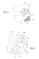
- Fig. 4 is a detail of a modified elevation adjusting mechanism.
- the first roughly adjustable support member 2 is identical with that of Fig. 1 except for the way in which the threaded bolt 26 is mounted to the rod 20.
- the bolt extends through a bore of rod 20, which , this time, is shown in the Fig. and has the reference numeral 219.
- the rod 20 has two claws 211 by which an adjusting nut 212 is held at the upper side of rod 20 at the end of bore 219.
- the adjusting nut 212 has a knurled wide diameter portion 213 that extends beyond the sides of rod 20 and can easily be held and rotated by the fingers of a user. By rotating the adjusting nut 212, the threaded bolt 26 is displaced axially.
- a fork 214 is formed having two fingers that extend along the lateral flanks of branch 11 and bear a bolt 215 which extends through a short slit 14 formed in branch 11.
- a locking nut 217 is shown at a lower end of threaded bolt 26, a locking nut 217 is shown.
- the adjusting nut has a hexagonal portion 218 that may be held by a wrench.
- the slot 12 of Fig. 1 is not required.
- This slit 14 is required because, in case of Fig. 1, the cage 28 and in case of Fig. 4, the threaded bolt 26 itself is only linearly displaceable, and the radius where the arms 29 or bolt 215 engage the branch 11 may vary according to the angular orientation of the first finely adjustable support member 1.
- This slit 14 might be replaced by a circular hole exactly fitting the arms 29 or the bolt 215, respectively if the threaded bolt 26 were pivotably mounted at the rod 20.
- Fig. 5 Another modified embodiment where no such slit or elongated hole is necessary is shown in Fig. 5.
- the rod 20 has a threaded bore in which the threaded bolt 26 is engaged and can be adjusted by turning around its axis.
- a locking nut 217 engaging threaded bolt 26 is provided at one side of rod 20, in this case at the upper side.
- the threaded bolt 26 has a cylindrical head portion 220 the top of which is shaped for engagement with a screwdriver.
- a cylindrical rod 15 held by branch 11 engages a circumferential groove 221 of this head portion.
- the branch 11 has a slot 12 as shown in Fig, 1, and the rod 15 extends across this slot 12.
- the depth of the groove 221 is set such that while threaded bolt 26 engages the bore of rod 20, the rod 15 will never come out of the groove 221. Elevation fine tuning is done by firstly turning threaded bolt 26 using a screwdriver until a satisfying elevation value is found, and then fixing the threaded bolt 26 using the locking nut 217.
- threaded bolt 26 there might be no thread for engagement with threaded bolt 26 in the bore of adjustable member 2.
- threaded bolt 26 might be held using two locking nuts 212, 217, just as shown in Fig. 4.
- Fig. 6 is a horizontal cross section taken along the same plane as in Fig. 3, illustrating a first modified embodiment of the azimuth adjusting mechanism.
- Two threaded bolts 45 extend through these bores.
- the bolts 45 have plate-shaped inward end portions facing each other.
- the projection 34 has a circular end portion 37 which is located in a space between the inward ends of the two bolts 45.
- the outward end of each bolt is provided with a hexagonal socket head for receiving an Allen wrench or with an equivalent structure for engaging with another type of screwdriver.
- this embodiment allows for a first coarse azimuth adjustment when mounting the adaptor 4 on the pole 5, and a second coarse adjustment by rotating the base member 3 over the angle defined by said clearance.
- the clearance is set to zero. Then the azimuth position of the antenna is adjusted by rotating both threaded bolts 45 to the same extent and in the same direction. When the correct azimuth position has been found, the mechanism is locked by rotating the bolts 45 in opposite directions, so that the circular end portion 37 is squeezed between then. Additionally, locking nuts 49 may be placed at the outward ends of the two bolts 45.
- the two threaded bolts 45 are replaced by a single cylindrical shaft 410 extending through both bores in the opposing side walls 36. Only one of these bores must have a thread that engages threaded first narrow portion 410 of shaft 411.
- a second narrow portion 412 of shaft 410 may be with or without thread.
- a circumferential groove 414 is formed in a thick portion 413 of shaft 410 between the two narrow portions 411, 412. The width of this groove 414 is selected such that it will receive the circular end portion 37 of projection 34 without a clearance in the axial direction of the shaft 410.
- This embodiment may be regarded as a variation of that of Fig. 6, in which the two threaded bolts 45 are combined into a single shaft, so that for carrying out the fine adjustment, it is no longer necessary to move the two bolts 45 separately.
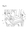
- an elevation position locking mechanism may be provided which is similar to the azimuth locking mechanism described above referring to Fig. 1.
- This elevation position locking mechanism is illustrated in Fig. 8. It comprises a locking nut 16 mounted at one end of rod 13 and an eccentric lever 17 similar to lever 44 of Fig. 1, which is mounted at the other end of rod 13 and is rotatable around an axis which is perpendicular to that of the rod 13.
- the rod 13 extends through vertical wings 38 of base member, through the upturned end portions 23 of crossbar 21 of the first roughly adjustable support member 2 and through the region joining branches 10, 11 of the first finely adjustable support member 1.
- the support members 1, 2 are not subject to any torque when the lever 17 is closed, so that an elevation adjustment carried out with the lever 17 open will not be accidentally destroyed when the lever 17 is closed. Accordingly, the holder can be easily and straightforwardly adjusted to a particular satellite by e.g. first performing a coarse adjustment of elevation and azimuth angles, so that a signal from the satellite is clearly detectable. Second, a fine adjustment of the azimuth angle is carried out, the azimuth adjustment mechanism is locked using lever 44, the elevation angle is finely adjusted, and finally the elevation adjusting mechanism is locked using lever 17.
Priority Applications (4)
| Application Number | Priority Date | Filing Date | Title |
|---|---|---|---|
| EP02292308A EP1401049B1 (de) | 2002-09-20 | 2002-09-20 | Halterung für eine Satellitenantenne |
| DE60218461T DE60218461T2 (de) | 2002-09-20 | 2002-09-20 | Halterung für eine Satellitenantenne |
| AT02292308T ATE355630T1 (de) | 2002-09-20 | 2002-09-20 | Halterung für eine satellitenantenne |
| US10/666,233 US6932307B2 (en) | 2002-09-20 | 2003-09-18 | Satellite antenna holder |
Applications Claiming Priority (1)
| Application Number | Priority Date | Filing Date | Title |
|---|---|---|---|
| EP02292308A EP1401049B1 (de) | 2002-09-20 | 2002-09-20 | Halterung für eine Satellitenantenne |
Publications (2)
| Publication Number | Publication Date |
|---|---|
| EP1401049A1 true EP1401049A1 (de) | 2004-03-24 |
| EP1401049B1 EP1401049B1 (de) | 2007-02-28 |
Family
ID=31896992
Family Applications (1)
| Application Number | Title | Priority Date | Filing Date |
|---|---|---|---|
| EP02292308A Expired - Lifetime EP1401049B1 (de) | 2002-09-20 | 2002-09-20 | Halterung für eine Satellitenantenne |
Country Status (4)
| Country | Link |
|---|---|
| US (1) | US6932307B2 (de) |
| EP (1) | EP1401049B1 (de) |
| AT (1) | ATE355630T1 (de) |
| DE (1) | DE60218461T2 (de) |
Cited By (2)
| Publication number | Priority date | Publication date | Assignee | Title |
|---|---|---|---|---|
| WO2011123726A2 (en) * | 2010-03-31 | 2011-10-06 | Linear Signal, Inc. | Apparatus and system for a double gimbal stabilization platform |
| US20160190675A1 (en) * | 2013-01-16 | 2016-06-30 | Vipula DASANAYAKA | Universal adapter plate assembly |
Families Citing this family (11)
| Publication number | Priority date | Publication date | Assignee | Title |
|---|---|---|---|---|
| US7600349B2 (en) | 2003-02-26 | 2009-10-13 | Unirac, Inc. | Low profile mounting system |
| TWI236180B (en) * | 2004-04-28 | 2005-07-11 | Wistron Neweb Corp | Fine tuning mechanism for rotation angle, and the satellite antenna using the same |
| JP5959794B2 (ja) | 2007-03-05 | 2016-08-02 | 株式会社日本触媒 | 吸水剤及びその製造方法 |
| EP2404954B1 (de) | 2009-03-04 | 2015-04-22 | Nippon Shokubai Co., Ltd. | Herstellungsverfahren für wasserabsorbierendes harz |
| CN101872884B (zh) * | 2009-04-23 | 2013-03-20 | 键吉科技股份有限公司 | 一种卫星碟形天线固定架及应用其的卫星碟形天线组 |
| US9422957B2 (en) | 2011-02-01 | 2016-08-23 | Thomas & Betts International Llc | Panel clamp |
| US20130048811A1 (en) * | 2011-08-30 | 2013-02-28 | Yi-Chen Tseng | A mounting kit |
| TWI497812B (zh) * | 2011-11-29 | 2015-08-21 | Wistron Neweb Corp | 角度調整機構及其天線系統 |
| US10079424B2 (en) | 2015-09-16 | 2018-09-18 | Viasat, Inc. | Multiple-assembly antenna positioner with eccentric shaft |
| CN112383929A (zh) * | 2020-11-04 | 2021-02-19 | 中国联合网络通信集团有限公司 | 天线调整设备、方法及计算机可读存储介质 |
| CN116315592B (zh) * | 2023-03-03 | 2023-09-29 | 河北北斗天汇科技有限公司 | 一种高稳定的卫星系统用抗干扰天线 |
Citations (8)
| Publication number | Priority date | Publication date | Assignee | Title |
|---|---|---|---|---|
| EP0038788A1 (de) * | 1980-04-15 | 1981-10-28 | Luxor Ab | Antennenhalterung |
| JPS61288502A (ja) * | 1985-06-14 | 1986-12-18 | Toshiba Corp | アンテナ方向調整装置 |
| GB2226705A (en) * | 1988-10-18 | 1990-07-04 | Steven Thomas Gribby | Motorised mount for a steerable dish antenna |
| JPH07307606A (ja) * | 1994-05-12 | 1995-11-21 | Sony Corp | 衛星放送受信アンテナ取付け装置 |
| JPH10107524A (ja) * | 1996-09-27 | 1998-04-24 | Dx Antenna Co Ltd | 衛星放送受信アンテナ取付装置 |
| US6045103A (en) * | 1998-07-17 | 2000-04-04 | Lucent Technologies, Inc. | Multiple axis bracket with keyed mount |
| US6211845B1 (en) * | 1999-09-28 | 2001-04-03 | Avaya Technology Corp. | Bracket mount for precise antenna adjustment |
| US6317093B1 (en) * | 2000-08-10 | 2001-11-13 | Raytheon Company | Satellite communication antenna pointing system |
Family Cites Families (3)
| Publication number | Priority date | Publication date | Assignee | Title |
|---|---|---|---|---|
| US3510877A (en) * | 1967-09-07 | 1970-05-05 | Int Standard Electric Corp | Antenna positioning device for following moving bodies |
| DE3127855A1 (de) * | 1981-07-15 | 1983-06-30 | AEG-Telefunken Nachrichtentechnik GmbH, 7150 Backnang | Halterung fuer eine in azimut- und elevationsrichtung schwenkbare parabolantenne |
| DE8629519U1 (de) * | 1986-11-05 | 1987-01-02 | Wilhelm Sihn Jun. Kg, 7532 Niefern-Oeschelbronn, De |
-
2002
- 2002-09-20 AT AT02292308T patent/ATE355630T1/de not_active IP Right Cessation
- 2002-09-20 EP EP02292308A patent/EP1401049B1/de not_active Expired - Lifetime
- 2002-09-20 DE DE60218461T patent/DE60218461T2/de not_active Expired - Lifetime
-
2003
- 2003-09-18 US US10/666,233 patent/US6932307B2/en not_active Expired - Lifetime
Patent Citations (8)
| Publication number | Priority date | Publication date | Assignee | Title |
|---|---|---|---|---|
| EP0038788A1 (de) * | 1980-04-15 | 1981-10-28 | Luxor Ab | Antennenhalterung |
| JPS61288502A (ja) * | 1985-06-14 | 1986-12-18 | Toshiba Corp | アンテナ方向調整装置 |
| GB2226705A (en) * | 1988-10-18 | 1990-07-04 | Steven Thomas Gribby | Motorised mount for a steerable dish antenna |
| JPH07307606A (ja) * | 1994-05-12 | 1995-11-21 | Sony Corp | 衛星放送受信アンテナ取付け装置 |
| JPH10107524A (ja) * | 1996-09-27 | 1998-04-24 | Dx Antenna Co Ltd | 衛星放送受信アンテナ取付装置 |
| US6045103A (en) * | 1998-07-17 | 2000-04-04 | Lucent Technologies, Inc. | Multiple axis bracket with keyed mount |
| US6211845B1 (en) * | 1999-09-28 | 2001-04-03 | Avaya Technology Corp. | Bracket mount for precise antenna adjustment |
| US6317093B1 (en) * | 2000-08-10 | 2001-11-13 | Raytheon Company | Satellite communication antenna pointing system |
Non-Patent Citations (3)
| Title |
|---|
| PATENT ABSTRACTS OF JAPAN vol. 011, no. 152 (E - 507) 16 May 1987 (1987-05-16) * |
| PATENT ABSTRACTS OF JAPAN vol. 1996, no. 03 29 March 1996 (1996-03-29) * |
| PATENT ABSTRACTS OF JAPAN vol. 1998, no. 09 31 July 1998 (1998-07-31) * |
Cited By (6)
| Publication number | Priority date | Publication date | Assignee | Title |
|---|---|---|---|---|
| WO2011123726A2 (en) * | 2010-03-31 | 2011-10-06 | Linear Signal, Inc. | Apparatus and system for a double gimbal stabilization platform |
| WO2011123726A3 (en) * | 2010-03-31 | 2011-11-24 | Linear Signal, Inc. | Apparatus and system for a double gimbal stabilization platform |
| US8564499B2 (en) | 2010-03-31 | 2013-10-22 | Linear Signal, Inc. | Apparatus and system for a double gimbal stabilization platform |
| US20160190675A1 (en) * | 2013-01-16 | 2016-06-30 | Vipula DASANAYAKA | Universal adapter plate assembly |
| US10897071B2 (en) * | 2013-01-16 | 2021-01-19 | Haeco Americas, Llc | Universal adapter plate assembly |
| US11575191B2 (en) | 2013-01-16 | 2023-02-07 | Haeco Americas, Llc | Universal adapter plate assembly |
Also Published As
| Publication number | Publication date |
|---|---|
| EP1401049B1 (de) | 2007-02-28 |
| DE60218461D1 (de) | 2007-04-12 |
| US6932307B2 (en) | 2005-08-23 |
| DE60218461T2 (de) | 2007-11-15 |
| ATE355630T1 (de) | 2006-03-15 |
| US20040069915A1 (en) | 2004-04-15 |
Similar Documents
| Publication | Publication Date | Title |
|---|---|---|
| US6932307B2 (en) | Satellite antenna holder | |
| US10317174B2 (en) | Modular system for mounting firearm accessories and method for attaching firearm accessory to firearm | |
| US6007085A (en) | Device for retaining a boot on a gliding board | |
| US8960106B2 (en) | Desk | |
| EP0321120B1 (de) | Klemmvorrichtung | |
| EP1867304B1 (de) | Vorrichtung zum Wirbelkörperersatz | |
| US20170231672A1 (en) | Dynamic bone plate compression device and method | |
| US20150090849A1 (en) | Medical device supporting apparatus | |
| EP0469304A1 (de) | Verbindung für Wirbelsäulefixator | |
| US20030023240A1 (en) | Device for connecting a longitudinal bar to a pedicle screw | |
| EP2063138A1 (de) | Kugelgelenkvorrichtung | |
| WO2014110504A1 (en) | Modular system for mounting firearm accessories and method for attaching firearm accessory to firearm | |
| US10028774B2 (en) | Transverse link having spherical ball joint | |
| US20040054371A1 (en) | Bone screw | |
| US6466181B1 (en) | Multi-satellite antenna mast alignment system | |
| US20100214749A1 (en) | Circuit Board Retainer with Insertion and Extraction Lever | |
| US20090254187A1 (en) | Tightenable Surgical Retractor Joint | |
| GB2028914A (en) | Furniture Hinge Mountings | |
| EP1524466B1 (de) | Vorrichtung mit Klemmhalterung für elektrische, elektronische ,optische und mechanische Einrichtungen und Komponenten | |
| US20030039506A1 (en) | Elbow connector structure for a cymbal support | |
| US5720270A (en) | Means for adjusting the sight pin of a bow | |
| US6224242B1 (en) | Luminaire | |
| CN114914693A (zh) | 用于天线装置的角度调节装置和天线装置 | |
| US20240052971A1 (en) | Adjustable Clamping Device and Leveling Base with Multidirectional Adjustment | |
| CN212718802U (zh) | 一种可翻转快装板 |
Legal Events
| Date | Code | Title | Description |
|---|---|---|---|
| PUAI | Public reference made under article 153(3) epc to a published international application that has entered the european phase |
Free format text: ORIGINAL CODE: 0009012 |
|
| AK | Designated contracting states |
Kind code of ref document: A1 Designated state(s): AT BE BG CH CY CZ DE DK EE ES FI FR GB GR IE IT LI LU MC NL PT SE SK TR |
|
| AX | Request for extension of the european patent |
Extension state: AL LT LV MK RO SI |
|
| 17P | Request for examination filed |
Effective date: 20040902 |
|
| 17Q | First examination report despatched |
Effective date: 20040924 |
|
| AKX | Designation fees paid |
Designated state(s): AT BE BG CH CY CZ DE DK EE ES FI FR GB GR IE IT LI LU MC NL PT SE SK TR |
|
| RAP1 | Party data changed (applicant data changed or rights of an application transferred) |
Owner name: THOMSON LICENSING |
|
| GRAP | Despatch of communication of intention to grant a patent |
Free format text: ORIGINAL CODE: EPIDOSNIGR1 |
|
| GRAS | Grant fee paid |
Free format text: ORIGINAL CODE: EPIDOSNIGR3 |
|
| GRAA | (expected) grant |
Free format text: ORIGINAL CODE: 0009210 |
|
| AK | Designated contracting states |
Kind code of ref document: B1 Designated state(s): AT BE BG CH CY CZ DE DK EE ES FI FR GB GR IE IT LI LU MC NL PT SE SK TR |
|
| PG25 | Lapsed in a contracting state [announced via postgrant information from national office to epo] |
Ref country code: BE Free format text: LAPSE BECAUSE OF FAILURE TO SUBMIT A TRANSLATION OF THE DESCRIPTION OR TO PAY THE FEE WITHIN THE PRESCRIBED TIME-LIMIT Effective date: 20070228 Ref country code: AT Free format text: LAPSE BECAUSE OF FAILURE TO SUBMIT A TRANSLATION OF THE DESCRIPTION OR TO PAY THE FEE WITHIN THE PRESCRIBED TIME-LIMIT Effective date: 20070228 Ref country code: DK Free format text: LAPSE BECAUSE OF FAILURE TO SUBMIT A TRANSLATION OF THE DESCRIPTION OR TO PAY THE FEE WITHIN THE PRESCRIBED TIME-LIMIT Effective date: 20070228 Ref country code: CH Free format text: LAPSE BECAUSE OF FAILURE TO SUBMIT A TRANSLATION OF THE DESCRIPTION OR TO PAY THE FEE WITHIN THE PRESCRIBED TIME-LIMIT Effective date: 20070228 Ref country code: NL Free format text: LAPSE BECAUSE OF FAILURE TO SUBMIT A TRANSLATION OF THE DESCRIPTION OR TO PAY THE FEE WITHIN THE PRESCRIBED TIME-LIMIT Effective date: 20070228 Ref country code: FI Free format text: LAPSE BECAUSE OF FAILURE TO SUBMIT A TRANSLATION OF THE DESCRIPTION OR TO PAY THE FEE WITHIN THE PRESCRIBED TIME-LIMIT Effective date: 20070228 Ref country code: LI Free format text: LAPSE BECAUSE OF FAILURE TO SUBMIT A TRANSLATION OF THE DESCRIPTION OR TO PAY THE FEE WITHIN THE PRESCRIBED TIME-LIMIT Effective date: 20070228 |
|
| REG | Reference to a national code |
Ref country code: GB Ref legal event code: FG4D |
|
| REG | Reference to a national code |
Ref country code: CH Ref legal event code: EP |
|
| REF | Corresponds to: |
Ref document number: 60218461 Country of ref document: DE Date of ref document: 20070412 Kind code of ref document: P |
|
| REG | Reference to a national code |
Ref country code: IE Ref legal event code: FG4D |
|
| PG25 | Lapsed in a contracting state [announced via postgrant information from national office to epo] |
Ref country code: BG Free format text: LAPSE BECAUSE OF THE APPLICANT RENOUNCES Effective date: 20070529 |
|
| PG25 | Lapsed in a contracting state [announced via postgrant information from national office to epo] |
Ref country code: SE Free format text: LAPSE BECAUSE OF FAILURE TO SUBMIT A TRANSLATION OF THE DESCRIPTION OR TO PAY THE FEE WITHIN THE PRESCRIBED TIME-LIMIT Effective date: 20070531 |
|
| PG25 | Lapsed in a contracting state [announced via postgrant information from national office to epo] |
Ref country code: ES Free format text: LAPSE BECAUSE OF FAILURE TO SUBMIT A TRANSLATION OF THE DESCRIPTION OR TO PAY THE FEE WITHIN THE PRESCRIBED TIME-LIMIT Effective date: 20070608 |
|
| PG25 | Lapsed in a contracting state [announced via postgrant information from national office to epo] |
Ref country code: PT Free format text: LAPSE BECAUSE OF FAILURE TO SUBMIT A TRANSLATION OF THE DESCRIPTION OR TO PAY THE FEE WITHIN THE PRESCRIBED TIME-LIMIT Effective date: 20070730 |
|
| NLV1 | Nl: lapsed or annulled due to failure to fulfill the requirements of art. 29p and 29m of the patents act | ||
| ET | Fr: translation filed | ||
| REG | Reference to a national code |
Ref country code: CH Ref legal event code: PL |
|
| PG25 | Lapsed in a contracting state [announced via postgrant information from national office to epo] |
Ref country code: SK Free format text: LAPSE BECAUSE OF FAILURE TO SUBMIT A TRANSLATION OF THE DESCRIPTION OR TO PAY THE FEE WITHIN THE PRESCRIBED TIME-LIMIT Effective date: 20070228 |
|
| PG25 | Lapsed in a contracting state [announced via postgrant information from national office to epo] |
Ref country code: CZ Free format text: LAPSE BECAUSE OF FAILURE TO SUBMIT A TRANSLATION OF THE DESCRIPTION OR TO PAY THE FEE WITHIN THE PRESCRIBED TIME-LIMIT Effective date: 20070228 |
|
| PLBE | No opposition filed within time limit |
Free format text: ORIGINAL CODE: 0009261 |
|
| STAA | Information on the status of an ep patent application or granted ep patent |
Free format text: STATUS: NO OPPOSITION FILED WITHIN TIME LIMIT |
|
| 26N | No opposition filed |
Effective date: 20071129 |
|
| PG25 | Lapsed in a contracting state [announced via postgrant information from national office to epo] |
Ref country code: GR Free format text: LAPSE BECAUSE OF FAILURE TO SUBMIT A TRANSLATION OF THE DESCRIPTION OR TO PAY THE FEE WITHIN THE PRESCRIBED TIME-LIMIT Effective date: 20070529 Ref country code: MC Free format text: LAPSE BECAUSE OF NON-PAYMENT OF DUE FEES Effective date: 20070930 Ref country code: IT Free format text: LAPSE BECAUSE OF FAILURE TO SUBMIT A TRANSLATION OF THE DESCRIPTION OR TO PAY THE FEE WITHIN THE PRESCRIBED TIME-LIMIT Effective date: 20070228 |
|
| PG25 | Lapsed in a contracting state [announced via postgrant information from national office to epo] |
Ref country code: IE Free format text: LAPSE BECAUSE OF NON-PAYMENT OF DUE FEES Effective date: 20070920 |
|
| PG25 | Lapsed in a contracting state [announced via postgrant information from national office to epo] |
Ref country code: EE Free format text: LAPSE BECAUSE OF FAILURE TO SUBMIT A TRANSLATION OF THE DESCRIPTION OR TO PAY THE FEE WITHIN THE PRESCRIBED TIME-LIMIT Effective date: 20070228 |
|
| PG25 | Lapsed in a contracting state [announced via postgrant information from national office to epo] |
Ref country code: CY Free format text: LAPSE BECAUSE OF FAILURE TO SUBMIT A TRANSLATION OF THE DESCRIPTION OR TO PAY THE FEE WITHIN THE PRESCRIBED TIME-LIMIT Effective date: 20070228 |
|
| PG25 | Lapsed in a contracting state [announced via postgrant information from national office to epo] |
Ref country code: LU Free format text: LAPSE BECAUSE OF NON-PAYMENT OF DUE FEES Effective date: 20070920 |
|
| PG25 | Lapsed in a contracting state [announced via postgrant information from national office to epo] |
Ref country code: TR Free format text: LAPSE BECAUSE OF FAILURE TO SUBMIT A TRANSLATION OF THE DESCRIPTION OR TO PAY THE FEE WITHIN THE PRESCRIBED TIME-LIMIT Effective date: 20070228 |
|
| REG | Reference to a national code |
Ref country code: FR Ref legal event code: PLFP Year of fee payment: 14 |
|
| REG | Reference to a national code |
Ref country code: FR Ref legal event code: PLFP Year of fee payment: 15 |
|
| REG | Reference to a national code |
Ref country code: DE Ref legal event code: R082 Ref document number: 60218461 Country of ref document: DE Representative=s name: DEHNS, DE Ref country code: DE Ref legal event code: R082 Ref document number: 60218461 Country of ref document: DE Representative=s name: HOFSTETTER, SCHURACK & PARTNER PATENT- UND REC, DE |
|
| REG | Reference to a national code |
Ref country code: FR Ref legal event code: PLFP Year of fee payment: 16 |
|
| REG | Reference to a national code |
Ref country code: FR Ref legal event code: PLFP Year of fee payment: 17 |
|
| REG | Reference to a national code |
Ref country code: FR Ref legal event code: TP Owner name: THOMSON LICENSING DTV, FR Effective date: 20180830 |
|
| REG | Reference to a national code |
Ref country code: GB Ref legal event code: 732E Free format text: REGISTERED BETWEEN 20180927 AND 20181005 |
|
| REG | Reference to a national code |
Ref country code: DE Ref legal event code: R082 Ref document number: 60218461 Country of ref document: DE Representative=s name: DEHNS, DE Ref country code: DE Ref legal event code: R081 Ref document number: 60218461 Country of ref document: DE Owner name: INTERDIGITAL MADISON PATENT HOLDINGS, FR Free format text: FORMER OWNER: THOMSON LICENSING, BOULOGNE-BILLANCOURT, FR |
|
| PGFP | Annual fee paid to national office [announced via postgrant information from national office to epo] |
Ref country code: FR Payment date: 20190925 Year of fee payment: 18 |
|
| PGFP | Annual fee paid to national office [announced via postgrant information from national office to epo] |
Ref country code: GB Payment date: 20190927 Year of fee payment: 18 |
|
| PGFP | Annual fee paid to national office [announced via postgrant information from national office to epo] |
Ref country code: DE Payment date: 20191129 Year of fee payment: 18 |
|
| REG | Reference to a national code |
Ref country code: DE Ref legal event code: R119 Ref document number: 60218461 Country of ref document: DE |
|
| GBPC | Gb: european patent ceased through non-payment of renewal fee |
Effective date: 20200920 |
|
| PG25 | Lapsed in a contracting state [announced via postgrant information from national office to epo] |
Ref country code: DE Free format text: LAPSE BECAUSE OF NON-PAYMENT OF DUE FEES Effective date: 20210401 Ref country code: FR Free format text: LAPSE BECAUSE OF NON-PAYMENT OF DUE FEES Effective date: 20200930 |
|
| PG25 | Lapsed in a contracting state [announced via postgrant information from national office to epo] |
Ref country code: GB Free format text: LAPSE BECAUSE OF NON-PAYMENT OF DUE FEES Effective date: 20200920 |