EP1400920A2 - Bildverarbeitungsvorrichtung und Ultraschalldiagnostikvorrichtung - Google Patents
Bildverarbeitungsvorrichtung und Ultraschalldiagnostikvorrichtung Download PDFInfo
- Publication number
- EP1400920A2 EP1400920A2 EP20030005341 EP03005341A EP1400920A2 EP 1400920 A2 EP1400920 A2 EP 1400920A2 EP 20030005341 EP20030005341 EP 20030005341 EP 03005341 A EP03005341 A EP 03005341A EP 1400920 A2 EP1400920 A2 EP 1400920A2
- Authority
- EP
- European Patent Office
- Prior art keywords
- image
- sub
- areas
- area
- image processing
- Prior art date
- Legal status (The legal status is an assumption and is not a legal conclusion. Google has not performed a legal analysis and makes no representation as to the accuracy of the status listed.)
- Withdrawn
Links
Images







Classifications
-
- A—HUMAN NECESSITIES
- A61—MEDICAL OR VETERINARY SCIENCE; HYGIENE
- A61B—DIAGNOSIS; SURGERY; IDENTIFICATION
- A61B8/00—Diagnosis using ultrasonic, sonic or infrasonic waves
- A61B8/08—Clinical applications
-
- A—HUMAN NECESSITIES
- A61—MEDICAL OR VETERINARY SCIENCE; HYGIENE
- A61B—DIAGNOSIS; SURGERY; IDENTIFICATION
- A61B8/00—Diagnosis using ultrasonic, sonic or infrasonic waves
-
- A—HUMAN NECESSITIES
- A61—MEDICAL OR VETERINARY SCIENCE; HYGIENE
- A61B—DIAGNOSIS; SURGERY; IDENTIFICATION
- A61B5/00—Measuring for diagnostic purposes; Identification of persons
- A61B5/103—Measuring devices for testing the shape, pattern, colour, size or movement of the body or parts thereof, for diagnostic purposes
- A61B5/107—Measuring physical dimensions, e.g. size of the entire body or parts thereof
- A61B5/1075—Measuring physical dimensions, e.g. size of the entire body or parts thereof for measuring dimensions by non-invasive methods, e.g. for determining thickness of tissue layer
-
- G—PHYSICS
- G06—COMPUTING OR CALCULATING; COUNTING
- G06T—IMAGE DATA PROCESSING OR GENERATION, IN GENERAL
- G06T5/00—Image enhancement or restoration
- G06T5/40—Image enhancement or restoration using histogram techniques
-
- G—PHYSICS
- G06—COMPUTING OR CALCULATING; COUNTING
- G06T—IMAGE DATA PROCESSING OR GENERATION, IN GENERAL
- G06T5/00—Image enhancement or restoration
- G06T5/90—Dynamic range modification of images or parts thereof
- G06T5/94—Dynamic range modification of images or parts thereof based on local image properties, e.g. for local contrast enhancement
-
- G—PHYSICS
- G06—COMPUTING OR CALCULATING; COUNTING
- G06T—IMAGE DATA PROCESSING OR GENERATION, IN GENERAL
- G06T7/00—Image analysis
- G06T7/10—Segmentation; Edge detection
- G06T7/12—Edge-based segmentation
-
- G—PHYSICS
- G06—COMPUTING OR CALCULATING; COUNTING
- G06V—IMAGE OR VIDEO RECOGNITION OR UNDERSTANDING
- G06V10/00—Arrangements for image or video recognition or understanding
- G06V10/70—Arrangements for image or video recognition or understanding using pattern recognition or machine learning
- G06V10/74—Image or video pattern matching; Proximity measures in feature spaces
- G06V10/75—Organisation of the matching processes, e.g. simultaneous or sequential comparisons of image or video features; Coarse-fine approaches, e.g. multi-scale approaches; using context analysis; Selection of dictionaries
- G06V10/755—Deformable models or variational models, e.g. snakes or active contours
-
- G—PHYSICS
- G06—COMPUTING OR CALCULATING; COUNTING
- G06V—IMAGE OR VIDEO RECOGNITION OR UNDERSTANDING
- G06V40/00—Recognition of biometric, human-related or animal-related patterns in image or video data
- G06V40/10—Human or animal bodies, e.g. vehicle occupants or pedestrians; Body parts, e.g. hands
- G06V40/16—Human faces, e.g. facial parts, sketches or expressions
- G06V40/161—Detection; Localisation; Normalisation
-
- A—HUMAN NECESSITIES
- A61—MEDICAL OR VETERINARY SCIENCE; HYGIENE
- A61B—DIAGNOSIS; SURGERY; IDENTIFICATION
- A61B8/00—Diagnosis using ultrasonic, sonic or infrasonic waves
- A61B8/46—Ultrasonic, sonic or infrasonic diagnostic devices with special arrangements for interfacing with the operator or the patient
- A61B8/461—Displaying means of special interest
-
- A—HUMAN NECESSITIES
- A61—MEDICAL OR VETERINARY SCIENCE; HYGIENE
- A61B—DIAGNOSIS; SURGERY; IDENTIFICATION
- A61B8/00—Diagnosis using ultrasonic, sonic or infrasonic waves
- A61B8/46—Ultrasonic, sonic or infrasonic diagnostic devices with special arrangements for interfacing with the operator or the patient
- A61B8/467—Ultrasonic, sonic or infrasonic diagnostic devices with special arrangements for interfacing with the operator or the patient characterised by special input means
-
- G—PHYSICS
- G06—COMPUTING OR CALCULATING; COUNTING
- G06T—IMAGE DATA PROCESSING OR GENERATION, IN GENERAL
- G06T2207/00—Indexing scheme for image analysis or image enhancement
- G06T2207/10—Image acquisition modality
- G06T2207/10132—Ultrasound image
-
- G—PHYSICS
- G06—COMPUTING OR CALCULATING; COUNTING
- G06T—IMAGE DATA PROCESSING OR GENERATION, IN GENERAL
- G06T2207/00—Indexing scheme for image analysis or image enhancement
- G06T2207/20—Special algorithmic details
- G06T2207/20004—Adaptive image processing
- G06T2207/20012—Locally adaptive
-
- G—PHYSICS
- G06—COMPUTING OR CALCULATING; COUNTING
- G06T—IMAGE DATA PROCESSING OR GENERATION, IN GENERAL
- G06T2207/00—Indexing scheme for image analysis or image enhancement
- G06T2207/20—Special algorithmic details
- G06T2207/20021—Dividing image into blocks, subimages or windows
-
- G—PHYSICS
- G06—COMPUTING OR CALCULATING; COUNTING
- G06T—IMAGE DATA PROCESSING OR GENERATION, IN GENERAL
- G06T2207/00—Indexing scheme for image analysis or image enhancement
- G06T2207/20—Special algorithmic details
- G06T2207/20092—Interactive image processing based on input by user
- G06T2207/20104—Interactive definition of region of interest [ROI]
-
- G—PHYSICS
- G06—COMPUTING OR CALCULATING; COUNTING
- G06T—IMAGE DATA PROCESSING OR GENERATION, IN GENERAL
- G06T2207/00—Indexing scheme for image analysis or image enhancement
- G06T2207/20—Special algorithmic details
- G06T2207/20172—Image enhancement details
- G06T2207/20192—Edge enhancement; Edge preservation
-
- G—PHYSICS
- G06—COMPUTING OR CALCULATING; COUNTING
- G06T—IMAGE DATA PROCESSING OR GENERATION, IN GENERAL
- G06T2207/00—Indexing scheme for image analysis or image enhancement
- G06T2207/30—Subject of image; Context of image processing
- G06T2207/30004—Biomedical image processing
-
- G—PHYSICS
- G06—COMPUTING OR CALCULATING; COUNTING
- G06T—IMAGE DATA PROCESSING OR GENERATION, IN GENERAL
- G06T2207/00—Indexing scheme for image analysis or image enhancement
- G06T2207/30—Subject of image; Context of image processing
- G06T2207/30196—Human being; Person
- G06T2207/30201—Face
Definitions
- This invention relates to an ultrasonic diagnostic device that generates an ultrasound image used in such a field as clinical medicine, and to an image processing device that processes an image displayed on various kinds of image-related devices, mobile phones and the like, and particularly to a technique for improving image quality such as contour extraction performed for the above-mentioned images.
- Image processing is sometimes performed by ultrasonic diagnostic devices, a wide range of image-related devices and the like for a specific object in an image (e.g. a soft tissue of a living body, a face) so as to extract its contour.
- a specific object in an image e.g. a soft tissue of a living body, a face
- Ultrasonic diagnostic devices have been widely used as indispensable devices in such a filed as clinical medicine, since they are capable of obtaining a two-dimensional (2D) image of an object to be examined without invasion as well as offering a high level of safety to a living body. The same is also applicable to other devices utilizing an ultrasonic wave employed in other fields.
- an ultrasonic diagnostic device receives an echo obtained when ultrasound emitted from an ultrasonic probe is partially reflected on reflection points and surfaces of tissue of an object of a living body to be examined, and generates an ultrasound image based on the received echo of the examined object. Since this reflected wave (ultrasonic echo) is feeble compared with the emitted ultrasound, amplification process (gain process) is performed for such reflected wave when a brightness signal is generated for displaying an image.
- Amplification (gain) control i.e. brightness control for image quality, is conventionally conducted through a method known as STC (Sensitivity Time Control) in which a plurality of sliders (e.g. 16 sliders) classified according to the depth level of an examined object are operated for making control. (Note that processing utilizing a logarithmic amplifier is used in some cases.)
- amplification process performed by a conventional ultrasonic diagnostic device is intended to control image quality by manually controlling contrast and dynamic range of an ultrasound image.
- One example is a "method for automatic image quality correction" disclosed in Japanese Laid-open Patent Application No. 2002-209891, in which gain control is automatically performed on the basis of the characteristics of an ultrasound image (e.g. a brightness signal of an ultrasound image represented by the Gaussian distribution shows a steep distribution, and its effective dynamic range is narrow). With this method, gain control is performed by measuring the distribution of brightness values for the whole image in a uniform manner.
- Another characteristic of an ultrasound image is that a part of the image is often unclear or does not properly appear on the image.
- a uniform processing is performed for the whole image, there occurs a possibility that the image quality of an ultrasound image that is partially unclear or does not properly appear on the image cannot be sufficiently improved.
- contour and boundary extraction methods Conventional methods for extracting contours and boundaries are effective on the assumption that a contour of a specific object shows up clearly in an ultrasound image.
- semiautomatic extraction methods in which a contour/boundary of an object is traced after it is given in advance an initial contour by a human hand.
- an "ultrasonic image diagnostic device" disclosed in Japanese Laid-open Patent Application No. H11-164834, a contour or the like of a target tissue is roughly traced by hand using a mouse or the like first, so as to extract a contour or the like serving as a guide, and then the start point is set for extracting the contour or the like.
- scan lines radiate in all directions from such start point.
- an area to be detected is determined.
- binarization is performed for image data within such detection area of the ultrasound image using a threshold value so as to detect a position on the contour or the like to be corrected.
- a further correction is made to the boundary of the contour or the like traced by hand so that a correct contour or the like can be obtained.
- an image of a human figure or a face taken by a variety of image-related devices capable of taking pictures (mobile phones, PDAs and the like are especially used) are often generated nowadays, but a person who takes a picture sometimes wishes to perform image processing for the image s/he desires by extracting the contour of a face or others in the image.
- a contour of a person especially its face
- Figs.1A ⁇ 1C are diagrams showing an example case where contour extraction performed for a human image is successful by the use of a conventional image-related device.
- Fig.1A is an original image taken by a mobile phone. As illustrated in Fig.1A, only a human face is shown in the original image. The following gives an explanation for the case where contour extraction is performed for such original image.
- a contour extraction method there is a method disclosed in Japanese Laid-open Patent Application No. 2002-224116 in which a contour of an object is extracted through two steps. According to this method, an initial contour is specified first (as illustrated in Fig.1B) and then a more precise contour is extracted (as illustrated in Fig.1C).
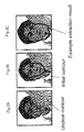
- Figs.2A ⁇ 2C are diagrams showing an example case where contour extraction performed for a human image ends in failure by the use of a conventional image-related device.
- Fig.2A is an original image equivalent to that shown in Fig.1A, but since there is a part that hinders contour extraction for the lower left-hand part of the image (e.g. a part where water vapor appears), Fig.2A is different from Fig.1A in that a part of the face contour is blurred.
- Fig.2B illustrates the case where an initial contour is specified
- processing intended for extracting a more precise contour results in a contour different from the real one.
- a part in the original image that hinders contour extraction there may occur a problem that an expected contour cannot be extracted.
- the present invention which is made in view of the above problems, aims at providing a variety of image processing methods to be employed according to local characteristics of an ultrasound image, as wells as providing automatic correction and contour extraction methods for images through such image processing methods.
- the image processing device and the ultrasonic diagnostic device divide an image into sub-areas and perform image processing appropriate to each of such sub-areas. Accordingly, it is possible for the present invention to overcome drawbacks of a conventional device such as that automatic image quality control does not function due to an image having a part which does not appear properly or having an unclear edge because contrast is low in some parts. Moreover, it is also possible for the present invention to overcome such a drawback of a conventional device as that contour/boundary extraction methods do not function properly due to the above reasons.
- the image processing device is an image processing device comprising: an image acquiring unit operable to acquire image data; an area dividing unit operable to divide an image represented by the acquired image data into a plurality of sub-areas; an area selecting unit operable to make a selection of one or more of the sub-areas; and an each area processing unit operable to perform image processing for each of said one or more selected sub-areas.
- the ultrasonic diagnostic device is an ultrasonic diagnostic device that displays an ultrasound image of an object subject to examination generated on the basis of a reflection of ultrasound and that comprises: an image acquiring unit operable to acquire image data; an area dividing unit operable to divide an ultrasound image represented by the acquired image data into a plurality of sub-areas; an area selecting unit operable to make a selection of one or more of the sub-areas; an each area processing unit operable to perform specific image processing for each of said one or more selected sub-areas; and a displaying unit operable to display an image of said one or more selected sub-areas for which the image processing is performed.
- the present invention may be implemented as a program which includes the characteristic units of the image processing device and the ultrasonic diagnostic device as its steps. Furthermore, it is also possible for such program not only to be stored in a ROM and the like in the image processing device and the ultrasonic diagnostic device but also be distributed through storage media such as CD-ROM, or over transmission media such as communications network.
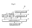
- Fig.3 is a block diagram showing an overview of a functional configuration of an ultrasonic diagnostic device 10 according to the present embodiment, which is one of the image processing devices according to the present invention.
- the ultrasonic diagnostic device 10 is capable of performing case-by-case processing for improving image quality even when a part of an ultrasound image is unclear or blurred.
- Such ultrasonic diagnostic device 10 is comprised of an ultrasonic search unit 11, a send/receive unit 12, a pulsation detecting unit 13, an operation unit 14, an image processing unit 15, and a data outputting unit 16.
- the ultrasonic search unit 11 which is generally called a probe, may be a probe that performs electronic scan based on the phased array method.
- the ultrasonic search unit 11 emits ultrasound (e.g. ultrasonic pulse) on the basis of a control signal sent by the send/receive unit 12. Furthermore, the ultrasonic search unit 11 converts the ultrasound (to be referred to as ultrasonic echo hereinafter) reflected from inside the living body of a subject into an electric signal, and sends it to the send/receive unit 12.
- the send/receive unit 12 which includes, for example, a CPU, a ROM, a RAM, or the like, has an overall control of the ultrasonic diagnostic device 10 as well as a function to send/receive ultrasound.
- Other constituent elements of the send/receive unit 12 include a sender/beam former for having the ultrasonic search unit 11 generate ultrasound and a receiver/beam former for receiving an electric signal sent from the ultrasonic search unit 11 that has detected an ultrasonic echo.
- the send/receive unit 12 performs processing such as amplification for the electric signal sent from the ultrasonic search unit 11, and sends such processed electric signal to the image processing unit 15. Furthermore, the send/receive unit 12 accepts an instruction from an operator via the operation unit 14.
- the pulsation detecting unit 13 an example of which is a pulsation sensor, converts the detected pulsation of the subject into an electric signal, and sends it to the image processing unit 15.
- the operation unit 14 which includes a switch, a touch panel and others, accepts from the operator operations performed on them, and sends to the send/receive unit 12 and the image processing unit 15 a control signal or the like corresponding to such operations.
- the image processing unit 15 generates image data of an ultrasound image based on the electric signal sent from the send/receive unit 12. Then, the image processing unit 15 divides the generated ultrasound image into sub-areas, and performs image processing for each sub-area. Furthermore, the image processing unit 15 reconstructs the ultrasound image on the basis of the processed image data, and sends the resulting image data to the data outputting unit 16.
- the data outputting unit 16 which is made up of a graphic accelerator, a scan converter and others, is capable of receiving image data of the ultrasound image reconstructed by the image processing unit 15 (e.g. B-mode ultrasound image) so as to show such image data on a liquid crystal display or the like serving as an observation monitor.
- image data of the ultrasound image reconstructed by the image processing unit 15 e.g. B-mode ultrasound image
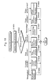
- Fig.4 is a block diagram showing a detailed functional configuration of the image processing unit 15 illustrated in Fig.3.
- image processing unit 15 is comprised of an image generating unit 110, a contour extracting unit 111, a controlling unit 112, an image memory 101, a general memory 102, and a computing unit 109.
- the computing unit 109 which features the present invention, is embodied by hardware like a specialized processor or the like, or software.
- Such computing unit 109 is made up of an area dividing unit 103, an evaluation value calculating unit 104, an each area processing unit 105, an area selecting unit 106, and an image reconstructing unit 107.
- the image generating unit 110 generates image data by performing A/D conversion or the like for an electric signal sent from the send/receive unit 12. Furthermore, the image generating unit 110 sends such generated image data to the controlling unit 112.
- Image data here refers to 2D brightness data or the like that is generated each time scanning is performed by the ultrasonic search unit 11 and that is to be displayed in B-mode and the like.
- the contour extracting unit 111 extracts a contour of such an object as the left ventricle (LV) of a heart on the basis of image data stored in the image memory 101, and generates contour data.
- a rough initial contour is extracted by performing "binarization” and "degeneracy” for an ultrasound image of a target object.
- SNAKES dynamic contour model
- Contour data here refers to data including coordinate (X axis and Y axis) data of a plurality of pixels making up a contour line of an examined object that is extracted on the basis of image data in one frame.
- the controlling unit 112 an example of which is a microcomputer having a ROM, a RAM and others, gives instructions mainly to the units in the image processing unit 15 to have them execute their own processing, and controls timing of such processing.
- the image memory 101 (e.g. a RAM) stores the image data of the ultrasound image generated by the image generating unit 110 and image data for which image processing has been performed by the below-described each area processing unit 105.
- the general memory 102 (e.g. a RAM) stores data other than image data of the ultrasound image generated by the image generating unit 110 (i.e. data stored in the image memory 101) such as data related to area division, data associated with a contour, data related to evaluation value calculation, and data related image processing).
- the area dividing unit 103 divides the ultrasound image generated by the image generating unit 110 into a plurality of sub-areas.
- Fig.5 explains an example of the method 1 ⁇ described above.
- a rectangular frame 200 indicates the outer edge of an area which can be displayed on the observation monitor of the data outputting unit 16, while a fan-shaped area enclosed by a bold line 201 indicates an area in the ultrasound image to be actually displayed on the observation monitor.
- Fig.5 shows eight divided sub-areas 310 ⁇ 380.
- an initial contour 210 is specified through automatic extraction or an operation of the operator, and then a gravity center G211 of such initial contour 210 is calculated. Then, a top T212 serving as a reference point on the initial contour 210 (i.e. the point indicating the biggest Y axis value in the initial contour 210) is identified, and then a point P213 and a point C214 are determined which intersect with the bold line 201 when a straight line between the gravity center G211 and the top T212 is extended.
- two straight lines 202 and 203 are determined that form angles of ( ⁇ /2) and (- ⁇ /4) between the straight line PC connecting the point P213 and the point C214. Then, points at which such two straight lines 202 and 203 intersect with the initial contour 210 are defined respectively as a point I215 and a point E217, and points at which such two straight lines 202 and 203 intersect with the bold line 201 are defined respectively as a point R216 and a point Q218.
- a closed area to be formed by connecting the point 1215, the point R216, the point Q218 and the point E217 indicates the sub-area 310, which is one of the divided eight sub-areas.
- the other sub-areas 320 ⁇ 380 are determined in the same manner.
- Fig.6 explains a variation of the method 1 ⁇ described above. While Fig.5 illustrates the case where the area between the initial contour 210 and the bold line 201 is the target of division (only the area to be actually displayed on the monitor is the target), Fig.6 illustrates the case where a target area to be divided is extended to the rectangular frame 200. Accordingly, a disclosed area to be formed by connecting the point I215, a point RR 219, a point V221, a point QQ 220, and the point E217 (the diagonally shaded area in Fig.6) indicates a determined sub-area 410 in this case.
- Fig.7 explains an example of the method 2 ⁇ described above. While the area between the initial contour 210 and the bold line 201 is the target of division in the method 1 ⁇ shown in Fig.5, Fig.7 illustrates the case where a boundary 501 is set at a position which is distant from the initial contour 210 by a certain number of pixels (e.g. 50 pixels) in the outward direction, and the doughnut-shaped area between the initial contour 210 and the boundary 501 is divided into eight sub-areas as in the above case. Accordingly, a disclosed area to be formed by connecting the point I215, a point J502, a point F503, and the point E217 (the diagonally shaded area in Fig.7) indicates a sub-area 510 determined by this method.
- a disclosed area to be formed by connecting the point I215, a point J502, a point F503, and the point E217 indicates a sub-area 510 determined by this method.
- Fig.8 explains a variation of the method 2 ⁇ described above. While Fig.7 illustrates the case where a target area of division is the doughnut-shaped area between the initial contour 210 and the boundary 501, Fig.8 illustrates the case where a boundary 601 is further set at a position which is distant from the initial contour 210 by a certain number of pixels (e.g. 12 pixels) in the inward direction, and the doughnut-shaped area between the boundary 601 and the boundary 501 is divided into eight sub-areas as in the above case. Accordingly, a disclosed area to be formed by connecting a point H602, the point J502, the point F503, and a point D603 (the diagonally shaded area in Fig.8) indicates a sub-area 610 determined by this method.
- a disclosed area to be formed by connecting a point H602, the point J502, the point F503, and a point D603 indicates a sub-area 610 determined by this method.
- Fig.9 explains an example of the method 3 ⁇ described above. While 1 ⁇ and 2 ⁇ are methods with which an ultrasound image is divided in a radial pattern with the gravity center G211 of the initial contour 210 as the starting point, Fig.9 illustrates an example case where sub-areas are generated by respectively dividing into quarters the lengths of the X axis and the Y axis within the area which can be displayed on the observation monitor.
- the rectangular frame 200 which is the area displayable on the monitor is divided into 16 sub-areas, each of which is equivalent to a rectangular sub-area 710 made up of "a" pixels in the X direction and "b" pixels in the Y direction.
- division methods illustrated in Figs.5 ⁇ 9 are only examples and therefore that an arbitrary existing division method (e.g. the straight line connecting the gravity center G211 and the point T212 illustrated in Fig.5 is set as a reference line, and an ultrasound image is divided into equal parts in a counterclockwise direction, each forming an angle of ⁇ /3) may be employed by the area dividing unit 103, without being limited to such example methods.
- an arbitrary existing division method e.g. the straight line connecting the gravity center G211 and the point T212 illustrated in Fig.5 is set as a reference line, and an ultrasound image is divided into equal parts in a counterclockwise direction, each forming an angle of ⁇ /3
- the evaluation value calculating unit 104 calculates an evaluation value used to quantitatively ascertain the quality, characteristics and the like of the ultrasound image for each sub-area divided by the area dividing unit 103.
- the maximum difference to be determined by deducting the minimum brightness value from the maximum brightness value is used as an evaluation value.
- an evaluation value may be either "the brightness distribution within a sub-area” or “the range width of brightness values occupying 80% of the entire brightness value histogram” that extends from the average value of the brightness values as its center.
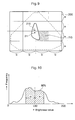
- Fig.10 illustrates the case where brightness values of a certain sub-area are distributed between 0 ⁇ 255 and the brightness average value is "120".
- the brightness values in the sub-area are sampled so as to determine " ⁇ ” when brightness values in 80% of the all pixels (800 pixels if a sub-area is made up of 1000 pixels) satisfy "120 ⁇ ( ⁇ : natural number), and "2 ⁇ " is used an evaluation value in this case.
- the above-listed evaluation value calculation methods (1) ⁇ (6) are only examples and therefore that an arbitrary existing expression and image processing may be employed by the evaluation value calculating unit 104 in order to calculate an evaluation value, without being limited to such example methods.
- the each area processing unit 105 performs image processing for each sub-area divided by the area dividing unit 103.
- Image processing here mainly refers to processing for improving image quality of each sub-area.
- processing may be one that facilitates evaluation processing performed by the evaluation value calculating unit 104 (e.g. normalization for controlling variations in the size of evaluation values among sub-areas), processing intended for enhancing performance of a post-connected apparatus, stabilizing its operations and improving its image quality, and other processing when the image is reconstructed by the image reconstructing unit 107 described later.
- the above-mentioned processing for improving image quality includes binarization, contrast controller, bias controller, noise reduction, Morphology process, edge extraction, edge enhancement, some of which, of course, may be combined for use.
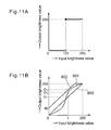
- Fig.11A is a diagram showing values of input brightness and output brightness when binarization is performed. As illustrated in Fig.11A, letting that the threshold value for the input brightness values is "128", an output brightness value varies between 0 and 255 inclusive, when an input brightness value is 128 or over.
- Fig.11B is a diagram showing a relationship between input brightness values and output brightness values when contrast controller and bias controller are performed.
- a curve 901 illustrated in Fig.11B indicates that input brightness values and output brightness values have a nonlinear relationship as a result of contrast controller.
- a curve 902 illustrated in Fig.11B shows an output brightness value being outputted which is an input brightness value added (biased) with a certain brightness value, as a result of bias controller. In this case, brightness value to be biased is "60".
- Morphology process which is a kind of nonlinear filtering processing, refers to filtering to be performed on the basis of such operations as “dilation” and "erosion” which are intended for extracting features from a given binary image or a contrast image. Note that detailed information for such Morphology process is described in "Kobatake H. Morphology (Corona Publishing Co., Ltd.)".
- Edge extraction refers to processing for extracting edge indicating area boundaries in an image (e.g. subject and background). There are variations including one using first differential filter and second differential filter.
- Edge enhancement refers to processing for enhancing the difference in the contrast level between the edge and other parts in an ultrasound image. Its variations include a method for transforming the distribution of brightness values.
- Fig.12 is a diagram showing an example method for transforming the distribution of brightness values.
- Fig.12 illustrates the case where a curve 1001 indicating that brightness values are centered around the average value (e.g. 120) of the brightness values is transformed into a curve 1002 indicating a less concentrated distribution.
- the area selecting unit 106 determines an arbitrary number of sub-areas from the sub-areas divided by the area dividing unit 103.
- a specified number of sub-areas may be selected from sub-areas with bigger evaluation values calculated by the evaluation value calculating unit 104 in descending order, or from sub-areas with smaller evaluation values in ascending order.
- "2 ⁇ " is used as an evaluation value determined on the basis of brightness values is taken as an example.
- sub-areas with bigger "2 ⁇ " in decreasing size order sub-areas with a clearer contrast (i.e. a wider contrast range) are selected.
- sub-areas with smaller "2 ⁇ " in increasing size order sub-areas with a more unclear contrast (i.e. a narrower contrast range) are selected.
- the image reconstructing unit 107 generates new image data by putting together ( i ) image data of the sub-areas which are divided by the area dividing unit 103 and for which image processing is performed by the each area processing unit 105, and (ii) the image data of the ultrasound image generated by the image generating unit 110.
- the image reconstructing unit 107 reconstructs the image by using only images within sub-areas specified by the area selecting unit 106 (in this case, one or more sub-areas do not appear as an image).
- the image reconstructing unit 107 it is also possible for the image reconstructing unit 107 to override an image of each sub-area on the original ultrasound image and to replace an image of each sub-area with the original image.
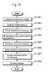
- Fig.15 is a flowchart showing an example flow of the entire processing performed by the ultrasonic diagnostic device 10.
- the image generating unit 110 generates an ultrasound image on the basis of an ultrasonic echo received via the ultrasonic search unit 11 and the send/receive unit 12 (S1301).
- the area dividing unit 103 divides the ultrasound image displayed on the observation monitor into a plurality of sub-areas (S1303).
- the evaluation value calculating unit 104 calculates an evaluation value for each sub-area divided in the above mentioned manner (S1304), and the each area processing unit 105 then performs image processing for such sub-areas on a per sub-area basis (S1305).
- the image reconstructing unit 107 reconstructs the ultrasound image on the observation monitor based on images of the selected sub-areas (S1307). Such reconstructed ultrasound image is then outputted to the data outputting unit 16 to be displayed on the observation monitor or the like.
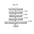
- Fig.16 is a flowchart showing an example of "Area division processing (S1303)" illustrated in Fig.15.
- the area dividing unit 103 calculates a gravity center G of the initial contour specified as above (S1401), so as to determine a central line running on such gravity center G (S1402).
- the area dividing unit 103 specifies a division method (e.g. the above mentioned method 1 ⁇ ) (S1403), and divides the ultrasound image into a plurality of sub-areas according to the specified division method (S1404).
- a division method e.g. the above mentioned method 1 ⁇
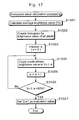
- Fig.17 is a flowchart showing an example of "Evaluation value calculation processing" illustrated in Fig.15. Note that Fig.17 illustrates the case where an evaluation value "2 ⁇ " related to the distribution of brightness values is calculated.
- the evaluation value calculating unit 104 calculates the average (YA) of brightness values of all pixels included as a target of evaluation value calculation (S1501). Then, the evaluation value calculating unit 104 creates a brightness value histogram that extends from the calculated average value for all the pixels (S1502).
- the evaluation value calculating unit 104 counts the number of pixels whose brightness value is "YA ⁇ " (S1504). Then, the evaluation value calculating unit 104 updates " ⁇ " by adding "1" to it (S1505), and judges whether the number of the counted pixels exceeds 80% of all the pixels, i.e. whether "YA ⁇ ⁇ >80%" (" ⁇ " in this inequality is the pre-updated value) is satisfied or not (S1506). If such condition is satisfied, the evaluation value calculating unit 104 sets "2 ⁇ " as an evaluation value (S1507).
- Fig.18 is a detailed flowchart showing "area-by-area processing" illustrated in Fig.15.
- the each area processing unit 105 accepts the contents of image processing to be carried out from the operator via the operation unit 14 (S1601).
- image processing includes the following processes: binarization, contrast controller, bias controller, noise reduction, Morphology process, edge extraction and edge enhancement.
- the each area processing unit 105 executes a specified process (S1602 ⁇ S1609). Note that at least one of the above processes (e.g. edge enhancement) may be executed as a default.
- Fig.19 is a flowchart showing the details of "Image reconstruction processing (S1307)" illustrated in Fig.15.
- the controlling unit 112 accepts via the operation unit 14 an operator's instruction as to the selection of sub-areas to be reconstructed as an image (S1701) and as to whether such sub-areas are overwritten over the original image or not (S1702). If an instruction indicating that overwriting is to be performed is accepted (S1702: Yes), the controlling unit 112 overwrites the ultrasound image generated by the image generating unit 110 with images of the selected sub-areas (S1703), and stores the resulting image in the image memory 101 (S1704).
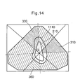
- Figs.13 and 14 are diagrams showing, in a simplified manner, the ultrasound image before and after image processing is performed by the each area processing unit 105.
- Fig.13 of the eight sub-areas divided by the area dividing unit 103, since brightness values of the entire sub-areas 310 and 330 are equally low (i.e. the entire images are blackish), a contour 1110 of an object is partly unclear.
- brightness values of the image of the sub-area 360 are equally high (i.e. the entire images are whitish)
- the contour 1110 of the object is partly unclear.
- Fig.14 depicts the ultrasound image shown in Fig.13 for which image processing is performed by the each area processing unit 105.
- image quality of the sub-areas 310, 330 and 360 is improved and the entire contour 1110 of the object has become clear.
- the ultrasonic diagnostic device As described above, with the ultrasonic diagnostic device according to the present embodiment, it is possible to reliably perform such processing as contour extraction of an object (e.g. LV) even for an image which is partly unclear or blurred.
- contour extraction of an object e.g. LV
- the image processing unit 15 is configured to be an integral part of the ultrasonic diagnostic device, it is also possible that the image generating unit 110 of the image processing unit 15 is replaced by a data inputting unit capable of accepting image data from outside the device so that the image processing unit 15 can serve as an image processing device having the functions described above.
- the image processing unit 15 is also capable of processing image data to be successively inputted in real time (moving image data). In this case, each unit of the image processing unit 15 performs processing on a per frame basis.
- the operator when extracting a contour of an object in an ultrasound image while tracking such object (e.g. when wishing to trace the internal wall of an LV for extracting its contour, while tracking the mitral valve annulus that separates the LV and the left atrium), the operator performs tracking as processing for the inside of sub-areas while performing processing for improving image quality for sub-areas with unclear contours. Then, after such tracking, by notifying from the area selecting unit the position of a sub-area in which the mitral valve annulus exists, it is possible to track and extract its contour in the image for which a conventional ultrasonic diagnostic device cannot perform contour extraction.
- Imaging quality includes contrast improvement by the use of an histogram equalizer or through noise cut, edge enhancement, or the like, but an arbitrary method may be used without being limited to such examples.
- tracking indicates, for example, pattern matching, inter-frame autocorrelation, methods for detecting a motion vector and the like, but an arbitrary method may be used without being limited to such examples.
- the first embodiment explains the case where the present invention is applied to an ultrasound image generated by the ultrasonic diagnostic device
- the second embodiment describes the case where the present invention is applied to an image generated by an image processing device such as a camera-equipped mobile phone.
- Fig.20 is a block diagram showing a functional configuration of an image processing device 20 according to the present embodiment.
- the image processing device 20 is capable of performing case-by-case processing for improving image quality even when a part of an image is unclear or blurred.
- Such image processing device 20 is comprised of a camera unit 21, a general controlling unit 22, the operation unit 14, the image processing unit 15, and the data outputting unit 16 (for convenience of explanation, functions of a general camera-equipped mobile phone such as communication capabilities and memory function are omitted in the image processing device 20).
- the image processing device 20 is equivalent to the ultrasonic diagnostic device 10 according to the first embodiment excluding that the image processing device 20 includes the camera unit 21 and the general controlling unit 22 instead of the ultrasonic search unit 11 and the send/receive unit 12 respectively. Note therefore that the following provides explanations focused especially on points that are different from the ultrasonic diagnostic device 10 according to the first embodiment.
- the camera unit 21, which includes a CCD and others, is a unit that takes a picture according to an operation of the operator inputted via the operation unit 14 (e.g. photoelectric conversion) and that generates image data.
- the general controlling unit 22 has an overall control of the image processing device 20, and includes a CPU, a ROM, a RAM or the like. Furthermore, the general controlling unit 22 receives image data generated by the camera unit 21 to store it to the RAM or the like, and sends to the image processing unit 15 the received image data as it is or image data read out from the RAM or the like, depending on an operator's operation inputted via the operation unit 14. Note that functions of the operation unit 14, the image processing unit 15 and the data outputting unit 16 are equivalent to corresponding units of the ultrasonic diagnostic device 10 according to the first embodiment.
- Figs.21A ⁇ 21C are diagrams showing an original image taken by a camera-equipped mobile phone or the like until when area division is performed for such original image.
- Fig.21A is an example original image.
- Fig.21B is a diagram showing the original image in Fig.21A for which an initial contour has been specified by a method equivalent to the one used in the ultrasonic diagnostic device 10 according to the first embodiment.
- Fig.21C is a diagram showing the original image in Fig.21B for which area division has been performed through the same method as used in the first embodiment.
- Figs.22A and 22B are diagrams showing the original image in which image processing is performed for sub-areas 23 and 24 selected from among divided sub-areas. Such sub-areas 23 and 24 shown in Fig.22A are two sub-areas selected using the same method presented in the first embodiment.
- Fig.22B is a diagram showing the original image for which image processing (e.g. contrast controller) has been performed for the sub-areas 23 and 24, as a result of which an improved face contour comes up.
- image processing e.g. contrast controller
- Fig.23A and 23B are diagrams showing that the initial contour is specified again and contour extraction is performed for the image including the sub-areas for which image processing has been performed in the present embodiment.
- Fig.23A is a diagram showing that the initial contour is specified again for the image including the sub-areas for which image processing has been performed.
- Fig.23B is a diagram showing a result of more precise contour extraction performed for the image illustrated in Fig.23A for which the initial contour is specified. As shown in Fig.23B, a desirable contour which is approximately the same as the real one is extracted in this case.
- Figs.24A ⁇ 24C are diagrams intended to explain an example function added to the image processing device 20.
- Fig.24B illustrates a result of performing contour extraction for the original image shown in Fig.24A.
- the image processing device 20, as illustrated in Fig.24D is capable of making the face contour "smaller” and "slimmer” on the basis of the extracted contour.
- a face contour can be made "smaller” or "slimmer", as shown in Fig.24C for example, by setting the scaling factor for the horizontal size (e.g. 0.7) lower than that for the vertical size (e.g. 0.9).
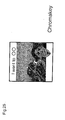
- Fig.25 is a diagram intended to explain another example function added to the image processing device 20.
- the image processing device 20 is capable of extracting a part of the image on the basis of the extracted contour and combining such extracted image with another image (e.g. a scenic image) so as to generate a new image (e.g. chromakey)
- another image e.g. a scenic image
- a new image e.g. chromakey
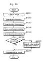
- Fig.26 is a flowchart showing an overall flow of processing performed by the image processing device 20.
- the image generating unit 15 generates an image on the basis of image data received via the camera unit 21 and the general controlling unit 22 (S2301).
- the general controlling unit 22 identifies an initial contour of a subject according to an operator' operation or through automatic extraction (S1302). Subsequently, the area dividing unit 103 divides the image shown on the display into a plurality of sub-areas (S1303). Then, the general controlling unit 22 accepts the selection of sub-areas from the operator (S1306), and gives an instruction to the each area processing unit 105 to perform image processing on a per sub-area basis (S1305).
- the general controlling unit 22 gives an instruction to each unit so as to have each unit specify the initial contour and extract the contour of the subject as described above (S2303).
- the image processing unit 15 performs processing and overlay for the obtained image at the instruction of the general controlling until 22 (S2304).
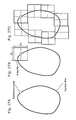
- an image including the contour line may be divided in a manner in which an area tile which is "2C" on a side is defined with the reference point as its starting point and other area tiles are placed in the same manner. Accordingly, as illustrated in Fig.27C, the image can be divided in accordance with eight area tiles by tracing the contour line. In this case, the area tiles are placed with their center being on the contour line.
- FIGs.28A and 28B Another division method is illustrated in Figs.28A and 28B, in which the area between an external rectangle and an internal rectangle is divided into sub-areas (area tiles).
- values of c (see Fig.27B), W1 ⁇ W6, and H1 ⁇ H6 may be changed to other values according to an instruction from the operator accepted via the operation unit 14 and that such changed values are used in corresponding methods for area division. Also note that the above dimensions are just examples and therefore that other dimensions are employed for image division.
- the image processing device As described above, with the image processing device according to the present embodiment, it is possible to extract from an image the contour of a face or the like whose contour appears unclear or blurred (i.e. improve image quality) by the use of the same method employed in the ultrasonic diagnostic device according to the first embodiment.
- the explanation provided in the present embodiment focuses on a face, it should be understood that the present invention is also applicable to the extraction of a contour of an arbitrary object.
Landscapes
- Engineering & Computer Science (AREA)
- Health & Medical Sciences (AREA)
- Life Sciences & Earth Sciences (AREA)
- Physics & Mathematics (AREA)
- Theoretical Computer Science (AREA)
- General Physics & Mathematics (AREA)
- General Health & Medical Sciences (AREA)
- Medical Informatics (AREA)
- Computer Vision & Pattern Recognition (AREA)
- Animal Behavior & Ethology (AREA)
- Public Health (AREA)
- Veterinary Medicine (AREA)
- Surgery (AREA)
- Molecular Biology (AREA)
- Heart & Thoracic Surgery (AREA)
- Biomedical Technology (AREA)
- Pathology (AREA)
- Biophysics (AREA)
- Software Systems (AREA)
- Oral & Maxillofacial Surgery (AREA)
- Multimedia (AREA)
- Radiology & Medical Imaging (AREA)
- Nuclear Medicine, Radiotherapy & Molecular Imaging (AREA)
- Human Computer Interaction (AREA)
- Computing Systems (AREA)
- Databases & Information Systems (AREA)
- Dentistry (AREA)
- Artificial Intelligence (AREA)
- Evolutionary Computation (AREA)
- Image Analysis (AREA)
- Image Processing (AREA)
- Ultra Sonic Daignosis Equipment (AREA)
Applications Claiming Priority (2)
| Application Number | Priority Date | Filing Date | Title |
|---|---|---|---|
| JP2002070562 | 2002-03-14 | ||
| JP2002070562 | 2002-03-14 |
Publications (1)
| Publication Number | Publication Date |
|---|---|
| EP1400920A2 true EP1400920A2 (de) | 2004-03-24 |
Family
ID=28035067
Family Applications (1)
| Application Number | Title | Priority Date | Filing Date |
|---|---|---|---|
| EP20030005341 Withdrawn EP1400920A2 (de) | 2002-03-14 | 2003-03-12 | Bildverarbeitungsvorrichtung und Ultraschalldiagnostikvorrichtung |
Country Status (5)
| Country | Link |
|---|---|
| US (1) | US20030174890A1 (de) |
| EP (1) | EP1400920A2 (de) |
| KR (1) | KR20030074414A (de) |
| CN (1) | CN1444907A (de) |
| CA (1) | CA2421468A1 (de) |
Cited By (1)
| Publication number | Priority date | Publication date | Assignee | Title |
|---|---|---|---|---|
| CN112508913A (zh) * | 2020-12-10 | 2021-03-16 | 国网江西省电力有限公司电力科学研究院 | 基于图像检测的电缆截面边沿检测方法 |
Families Citing this family (48)
| Publication number | Priority date | Publication date | Assignee | Title |
|---|---|---|---|---|
| KR100750424B1 (ko) * | 2004-03-03 | 2007-08-21 | 닛본 덴끼 가부시끼가이샤 | 화상 유사도 산출 시스템, 화상 검색 시스템, 화상 유사도산출 방법 및 화상 유사도 산출용 프로그램 |
| CN100522070C (zh) * | 2004-03-15 | 2009-08-05 | 株式会社日立医药 | 医用图像诊断装置 |
| US20050249429A1 (en) * | 2004-04-22 | 2005-11-10 | Fuji Photo Film Co., Ltd. | Method, apparatus, and program for image processing |
| JP4299189B2 (ja) * | 2004-05-27 | 2009-07-22 | アロカ株式会社 | 超音波診断装置及び画像処理方法 |
| WO2006044996A2 (en) * | 2004-10-15 | 2006-04-27 | The Trustees Of Columbia University In The City Of New York | System and method for automated boundary detection of body structures |
| US10687785B2 (en) | 2005-05-12 | 2020-06-23 | The Trustees Of Columbia Univeristy In The City Of New York | System and method for electromechanical activation of arrhythmias |
| EP1937151A4 (de) * | 2005-09-19 | 2011-07-06 | Univ Columbia | Systeme und verfahren zur öffnung der blut-hirn-schranke einer person mit ultraschall |
| WO2007052184A2 (en) * | 2005-11-02 | 2007-05-10 | Koninklijke Philips Electronics N. V. | Image processing system and method for silhouette rendering and display of images during interventional procedures |
| WO2007067987A2 (en) * | 2005-12-09 | 2007-06-14 | The Trustees Of Columbia University In The City Ofnew York | Systems and methods for elastography imaging |
| US8369645B2 (en) * | 2006-05-17 | 2013-02-05 | Sony Corporation | Image correction circuit, image correction method and image display |
| US7600151B2 (en) * | 2007-01-25 | 2009-10-06 | Inventec Corporation | RAID capacity expansion interruption recovery handling method and system |
| US20080317355A1 (en) * | 2007-06-21 | 2008-12-25 | Trw Automotive U.S. Llc | Method and apparatus for determining characteristics of an object from a contour image |
| KR100861991B1 (ko) * | 2008-02-25 | 2008-10-07 | (주)태성종합기술 | 이미지분석법에 의한 슬러지 침전상태 감지방법 |
| WO2011035312A1 (en) | 2009-09-21 | 2011-03-24 | The Trustees Of Culumbia University In The City Of New York | Systems and methods for opening of a tissue barrier |
| JP5016541B2 (ja) * | 2008-04-01 | 2012-09-05 | 富士フイルム株式会社 | 画像処理装置および方法並びにプログラム |
| WO2010014977A1 (en) | 2008-08-01 | 2010-02-04 | The Trustees Of Columbia University In The City Of New York | Systems and methods for matching and imaging tissue characteristics |
| JP5115398B2 (ja) * | 2008-08-27 | 2013-01-09 | セイコーエプソン株式会社 | 画像処理装置、画像処理方法および画像処理プログラム |
| WO2010030819A1 (en) | 2008-09-10 | 2010-03-18 | The Trustees Of Columbia University In The City Of New York | Systems and methods for opening a tissue |
| KR101028718B1 (ko) * | 2008-09-30 | 2011-04-14 | 주식회사 바이오넷 | 초음파 진단 장치에서의 관심 영역에 대한 고해상도 표현방법 |
| CN101822550B (zh) * | 2009-03-06 | 2012-01-04 | 复旦大学 | 超声彩色血流成像中基于动态区域划分的杂波抑制方法 |
| EP2417913A4 (de) * | 2009-04-06 | 2014-07-23 | Hitachi Medical Corp | Diagnosevorrichtung zur anzeige medizinischer bilder, verfahren zur einstellung von interessenbereichen, vorrichtung zur verarbeitung medizinischer bilder und programm zur einstellung von interessenbereichen |
| JP5596938B2 (ja) * | 2009-06-02 | 2014-09-24 | キヤノン株式会社 | 画像処理装置、画像処理方法、及びプログラム |
| JP5586203B2 (ja) * | 2009-10-08 | 2014-09-10 | 株式会社東芝 | 超音波診断装置、超音波画像処理装置及び超音波画像処理プログラム |
| KR101124084B1 (ko) * | 2010-06-17 | 2012-03-20 | 삼성전기주식회사 | 초음파 영상 장치 및 초음파 영상 생성 방법 |
| KR101124153B1 (ko) * | 2010-08-20 | 2012-03-22 | 삼성전기주식회사 | 초음파 영상 장치 및 초음파 영상 생성 방법 |
| JP5594282B2 (ja) * | 2011-03-31 | 2014-09-24 | カシオ計算機株式会社 | 画像処理装置 |
| WO2012162664A1 (en) | 2011-05-26 | 2012-11-29 | The Trustees Of Columbia University In The City Of New York | Systems and methods for opening of a tissue barrier in primates |
| KR101501516B1 (ko) * | 2012-01-09 | 2015-03-11 | 삼성메디슨 주식회사 | 촬영된 영상의 확대 영상과 휘도 정보를 이용하여 촬영된 대상체를 메저링하기 위한 방법 및 그 장치 |
| WO2014059170A1 (en) | 2012-10-10 | 2014-04-17 | The Trustees Of Columbia University In The City Of New York | Systems and methods for mechanical mapping of cardiac rhythm |
| US9247921B2 (en) | 2013-06-07 | 2016-02-02 | The Trustees Of Columbia University In The City Of New York | Systems and methods of high frame rate streaming for treatment monitoring |
| US10322178B2 (en) | 2013-08-09 | 2019-06-18 | The Trustees Of Columbia University In The City Of New York | Systems and methods for targeted drug delivery |
| US10028723B2 (en) | 2013-09-03 | 2018-07-24 | The Trustees Of Columbia University In The City Of New York | Systems and methods for real-time, transcranial monitoring of blood-brain barrier opening |
| KR101599891B1 (ko) | 2014-09-19 | 2016-03-04 | 삼성전자주식회사 | 초음파 진단장치, 방법 및 컴퓨터 판독 가능한 저장매체 |
| WO2016088758A1 (ja) * | 2014-12-01 | 2016-06-09 | 国立研究開発法人産業技術総合研究所 | 超音波検査システム及び超音波検査方法 |
| CN104461009B (zh) * | 2014-12-22 | 2018-01-09 | 百度在线网络技术(北京)有限公司 | 物体的测量方法和智能设备 |
| KR101946576B1 (ko) * | 2016-12-23 | 2019-02-11 | 삼성전자주식회사 | 의료 영상 장치 및 의료 영상 처리 방법 |
| JP6829437B2 (ja) * | 2017-03-03 | 2021-02-10 | 国立大学法人 東京大学 | 生体内運動追跡装置 |
| CN108464845A (zh) * | 2018-01-22 | 2018-08-31 | 苏州佳世达电通有限公司 | 一种超声波探头的异常侦测方法和超声波诊断系统 |
| CN113556979B (zh) * | 2019-03-19 | 2025-02-11 | 奥林巴斯株式会社 | 超声波观测装置、超声波观测装置的工作方法以及超声波观测装置的工作程序 |
| CN110879985B (zh) * | 2019-11-18 | 2022-11-11 | 西南交通大学 | 一种抗噪声数据的人脸识别模型训练方法 |
| CN110931130B (zh) * | 2019-12-30 | 2023-06-09 | 南京大学 | 一种基于b超信号评估呼吸和心动周期的方法 |
| CN111242869B (zh) * | 2020-01-17 | 2023-04-28 | 广东驰行电力设备有限公司 | 对照片进行背景过滤的方法 |
| CN111353958B (zh) * | 2020-02-28 | 2023-07-25 | 北京东软医疗设备有限公司 | 图像处理方法、装置及系统 |
| CN114259257B (zh) * | 2020-09-16 | 2025-03-11 | 深圳迈瑞生物医疗电子股份有限公司 | 确定面积的方法、超声装置及计算机存储介质 |
| CN113916979A (zh) * | 2021-09-17 | 2022-01-11 | 秒针信息技术有限公司 | 工件缺陷检测方法、装置、系统及计算机可读存储介质 |
| CN113838029B (zh) * | 2021-09-24 | 2024-04-30 | 南京中赢医疗科技有限公司 | 医疗影像评价方法及系统 |
| CN114757950B (zh) * | 2022-06-15 | 2022-11-01 | 深圳瀚维智能医疗科技有限公司 | 超声图像处理方法、装置以及计算机可读存储介质 |
| CN117243637B (zh) * | 2023-10-19 | 2024-04-19 | 河北港口集团有限公司秦皇岛中西医结合医院 | 一种超声心动图图像识别方法 |
Family Cites Families (9)
| Publication number | Priority date | Publication date | Assignee | Title |
|---|---|---|---|---|
| WO1995015537A1 (en) * | 1993-11-30 | 1995-06-08 | Arch Development Corporation | Automated method and system for the alignment and correlation of images from two different modalities |
| US5797844A (en) * | 1995-08-23 | 1998-08-25 | Kabushiki Kaisha Toshiba | Method and apparatus for ultrasonic imaging and ultrasonic image processing |
| WO1999005640A1 (en) * | 1997-07-25 | 1999-02-04 | Arch Development Corporation | Method and system for the segmentation of lung regions in lateral chest radiographs |
| JP3809742B2 (ja) * | 1999-03-29 | 2006-08-16 | コニカミノルタビジネステクノロジーズ株式会社 | コントラスト補正を行う画像処理装置および方法 |
| JP4407985B2 (ja) * | 1999-09-02 | 2010-02-03 | キヤノン株式会社 | 画像処理方法及び装置並びに記憶媒体 |
| US6907144B1 (en) * | 1999-10-06 | 2005-06-14 | Eastman Kodak Company | Noise reduction method, apparatus, and program for digital image processing |
| EP1111909A1 (de) * | 1999-12-23 | 2001-06-27 | Philips Patentverwaltung GmbH | Vorrichtung und Verfahren zur Darstellung eines aus mehreren Teilbereichen zusammengesetzten Bildes |
| US6829382B2 (en) * | 2001-06-13 | 2004-12-07 | Shih-Jong J. Lee | Structure-guided automatic alignment for image processing |
| US7218772B2 (en) * | 2002-06-10 | 2007-05-15 | Ut-Battelle Llc | Method for non-referential defect characterization using fractal encoding and active contours |
-
2003
- 2003-03-11 US US10/384,555 patent/US20030174890A1/en not_active Abandoned
- 2003-03-11 CA CA 2421468 patent/CA2421468A1/en not_active Abandoned
- 2003-03-12 EP EP20030005341 patent/EP1400920A2/de not_active Withdrawn
- 2003-03-13 KR KR10-2003-0015642A patent/KR20030074414A/ko not_active Withdrawn
- 2003-03-14 CN CN03119985A patent/CN1444907A/zh active Pending
Cited By (1)
| Publication number | Priority date | Publication date | Assignee | Title |
|---|---|---|---|---|
| CN112508913A (zh) * | 2020-12-10 | 2021-03-16 | 国网江西省电力有限公司电力科学研究院 | 基于图像检测的电缆截面边沿检测方法 |
Also Published As
| Publication number | Publication date |
|---|---|
| CA2421468A1 (en) | 2003-09-14 |
| CN1444907A (zh) | 2003-10-01 |
| KR20030074414A (ko) | 2003-09-19 |
| US20030174890A1 (en) | 2003-09-18 |
Similar Documents
| Publication | Publication Date | Title |
|---|---|---|
| EP1400920A2 (de) | Bildverarbeitungsvorrichtung und Ultraschalldiagnostikvorrichtung | |
| US12329570B2 (en) | Ultrasound system with an artificial neural network for guided liver imaging | |
| US8270696B2 (en) | Image slice segmentation using midpoints of contour anchor points | |
| US6055295A (en) | Method and apparatus for automatic collimation in x-ray peripheral imaging | |
| EP2016905B1 (de) | Diagnostische Ultraschallvorrichtung | |
| US9119559B2 (en) | Method and system of generating a 3D visualization from 2D images | |
| US7110583B2 (en) | Ultrasonic diagnostic device and image processing device | |
| CN100563578C (zh) | 用于形成3d超声图像的设备和方法 | |
| CN105913432B (zh) | 基于ct序列图像的主动脉提取方法及装置 | |
| US20030095121A1 (en) | Vessel detection by mean shift based ray propagation | |
| JPH1023452A (ja) | 画像抽出装置および方法 | |
| JP2005334317A (ja) | 超音波診断装置及び画像処理方法 | |
| US7817837B2 (en) | Image processing device and method | |
| EP3933759B1 (de) | Bildverarbeitungsverfahren, vorrichtung und system sowie elektronische vorrichtung und speichermedium | |
| CN101467892B (zh) | 超声波诊断装置、超声波图像处理装置及方法 | |
| US20060184021A1 (en) | Method of improving the quality of a three-dimensional ultrasound doppler image | |
| US7460701B2 (en) | Nodule detection | |
| EP2016906A2 (de) | Diagnostisches Ultraschallgerät | |
| JP2003334194A (ja) | 画像処理装置及び超音波診断装置 | |
| EP1225542A2 (de) | Segmentierung von tomographischen Daten | |
| US8280125B2 (en) | Method and system for segmentation of tubular structures using pearl strings | |
| US8073232B2 (en) | Method and system for diaphragm segmentation in chest X-ray radiographs | |
| EP1796037B1 (de) | Bildverarbeitungssystem und Verfahren zur Verstärkungsregelung für Farbdopplerbilder | |
| JP4679095B2 (ja) | 画像処理装置、画像処理方法、及びプログラム | |
| US20240062439A1 (en) | Display processing apparatus, method, and program |
Legal Events
| Date | Code | Title | Description |
|---|---|---|---|
| PUAI | Public reference made under article 153(3) epc to a published international application that has entered the european phase |
Free format text: ORIGINAL CODE: 0009012 |
|
| AK | Designated contracting states |
Kind code of ref document: A2 Designated state(s): AT BE BG CH CY CZ DE DK EE ES FI FR GB GR HU IE IT LI LU MC NL PT SE SI SK TR |
|
| AX | Request for extension of the european patent |
Extension state: AL LT LV MK RO |
|
| RAP1 | Party data changed (applicant data changed or rights of an application transferred) |
Owner name: PANASONIC CORPORATION |
|
| STAA | Information on the status of an ep patent application or granted ep patent |
Free format text: STATUS: THE APPLICATION HAS BEEN WITHDRAWN |
|
| 18W | Application withdrawn |
Effective date: 20090115 |