EP1400690A2 - Rückschlagventil für Vakuumpumpen - Google Patents
Rückschlagventil für Vakuumpumpen Download PDFInfo
- Publication number
- EP1400690A2 EP1400690A2 EP03255709A EP03255709A EP1400690A2 EP 1400690 A2 EP1400690 A2 EP 1400690A2 EP 03255709 A EP03255709 A EP 03255709A EP 03255709 A EP03255709 A EP 03255709A EP 1400690 A2 EP1400690 A2 EP 1400690A2
- Authority
- EP
- European Patent Office
- Prior art keywords
- ball
- valve
- valve seat
- insert
- passage
- Prior art date
- Legal status (The legal status is an assumption and is not a legal conclusion. Google has not performed a legal analysis and makes no representation as to the accuracy of the status listed.)
- Withdrawn
Links
- 239000012530 fluid Substances 0.000 claims abstract description 26
- 239000013536 elastomeric material Substances 0.000 claims abstract description 12
- 239000002184 metal Substances 0.000 claims description 14
- 229910052751 metal Inorganic materials 0.000 claims description 14
- 239000000463 material Substances 0.000 claims description 12
- 230000005484 gravity Effects 0.000 claims description 8
- 238000011144 upstream manufacturing Methods 0.000 claims description 6
- 238000000034 method Methods 0.000 claims description 4
- 229920006169 Perfluoroelastomer Polymers 0.000 claims description 3
- 238000005266 casting Methods 0.000 claims description 3
- 229920001973 fluoroelastomer Polymers 0.000 claims description 3
- 239000000919 ceramic Substances 0.000 claims description 2
- 229920000642 polymer Polymers 0.000 claims 1
- 239000007789 gas Substances 0.000 description 27
- 150000001875 compounds Chemical class 0.000 description 14
- YCKRFDGAMUMZLT-UHFFFAOYSA-N Fluorine atom Chemical compound [F] YCKRFDGAMUMZLT-UHFFFAOYSA-N 0.000 description 5
- 229920001971 elastomer Polymers 0.000 description 5
- 239000000806 elastomer Substances 0.000 description 5
- 229910052731 fluorine Inorganic materials 0.000 description 5
- 239000011737 fluorine Substances 0.000 description 5
- 229920001343 polytetrafluoroethylene Polymers 0.000 description 4
- 239000004810 polytetrafluoroethylene Substances 0.000 description 4
- 239000007787 solid Substances 0.000 description 4
- -1 for example Polymers 0.000 description 3
- 238000005086 pumping Methods 0.000 description 3
- 229920002449 FKM Polymers 0.000 description 2
- 238000012986 modification Methods 0.000 description 2
- 230000004048 modification Effects 0.000 description 2
- 238000000465 moulding Methods 0.000 description 2
- 238000007789 sealing Methods 0.000 description 2
- 230000003213 activating effect Effects 0.000 description 1
- 229910010293 ceramic material Inorganic materials 0.000 description 1
- 239000011248 coating agent Substances 0.000 description 1
- 238000000576 coating method Methods 0.000 description 1
- 230000006835 compression Effects 0.000 description 1
- 238000007906 compression Methods 0.000 description 1
- 238000005260 corrosion Methods 0.000 description 1
- 230000007797 corrosion Effects 0.000 description 1
- 238000003780 insertion Methods 0.000 description 1
- 230000037431 insertion Effects 0.000 description 1
- 238000004519 manufacturing process Methods 0.000 description 1
- 238000005058 metal casting Methods 0.000 description 1
- 150000002739 metals Chemical class 0.000 description 1
- 229910001220 stainless steel Inorganic materials 0.000 description 1
- 239000010935 stainless steel Substances 0.000 description 1
- 239000000126 substance Substances 0.000 description 1
Images

Classifications
-
- F—MECHANICAL ENGINEERING; LIGHTING; HEATING; WEAPONS; BLASTING
- F04—POSITIVE - DISPLACEMENT MACHINES FOR LIQUIDS; PUMPS FOR LIQUIDS OR ELASTIC FLUIDS
- F04B—POSITIVE-DISPLACEMENT MACHINES FOR LIQUIDS; PUMPS
- F04B39/00—Component parts, details, or accessories, of pumps or pumping systems specially adapted for elastic fluids, not otherwise provided for in, or of interest apart from, groups F04B25/00 - F04B37/00
- F04B39/10—Adaptations or arrangements of distribution members
- F04B39/1006—Adaptations or arrangements of distribution members the members being ball valves
-
- F—MECHANICAL ENGINEERING; LIGHTING; HEATING; WEAPONS; BLASTING
- F16—ENGINEERING ELEMENTS AND UNITS; GENERAL MEASURES FOR PRODUCING AND MAINTAINING EFFECTIVE FUNCTIONING OF MACHINES OR INSTALLATIONS; THERMAL INSULATION IN GENERAL
- F16K—VALVES; TAPS; COCKS; ACTUATING-FLOATS; DEVICES FOR VENTING OR AERATING
- F16K15/00—Check valves
- F16K15/02—Check valves with guided rigid valve members
- F16K15/04—Check valves with guided rigid valve members shaped as balls
- F16K15/048—Ball features
-
- F—MECHANICAL ENGINEERING; LIGHTING; HEATING; WEAPONS; BLASTING
- F16—ENGINEERING ELEMENTS AND UNITS; GENERAL MEASURES FOR PRODUCING AND MAINTAINING EFFECTIVE FUNCTIONING OF MACHINES OR INSTALLATIONS; THERMAL INSULATION IN GENERAL
- F16K—VALVES; TAPS; COCKS; ACTUATING-FLOATS; DEVICES FOR VENTING OR AERATING
- F16K25/00—Details relating to contact between valve members and seats
- F16K25/005—Particular materials for seats or closure elements
Definitions
- the invention relates to non-return valves for vacuum pumps.
- Non-return valves sometimes referred to as check valves, are commonly used with vacuum pumps.
- a non-return valve is most often used on the exhaust side of a dry vacuum pump and is arranged to permit gas/vapour to exhaust from the pump and prevent backflow of the gas/vapour.
- a known non-return valve makes use of a ball working against gravity.
- the ball seats against a valve seat until such time as the exhaust pressure is sufficient to lift the ball from the seat against gravity.
- the valve is open to permit the passage of gas/vapour from the pump. If the exhaust pressure falls to the extent it cannot support the ball against gravity, the ball falls back against the valve seat to prevent backflow of gas/vapour into the pump.
- the valve seat of the known non-return valve is made of metal and in order to provide good gas sealing properties, the ball is either made of elastomeric material, or comprises a metal former coated with an elastomeric material.
- the elastomer is required to be sufficiently compliant to provide a good gas seal.
- the known non-return valve works well, but there are problems encountered when corrosive gases/vapours are pumped.
- An example of such a gas vapour is one containing fluorine.
- the elastomeric compounds normally used in vacuum pump sealing such as fluoroelastomers, for example, Viton (Trade Name), are prone to attack by the fluorine content of vacuum pump exhaust.
- the metal components are also attacked by these corrosive gases/vapours, but are typically much more resistant than the elastomeric compounds normally used.
- elastomers having an increased resistance to attack can be used.
- elastomers with increased resistance to fluorine attack are perfluoroelastomers, such as Chemraz (Registered Trade Mark) and Kalrez (Registered Trade Mark).
- Chemraz Registered Trade Mark
- Kalrez Registered Trade Mark
- these materials are significantly more expensive than the more commonly used materials such as Viton and while a satisfactory ball made of solid Chemraz or Kelraz can be produced, this adds enormously to the cost of producing a non-return valve.
- An object of the invention is to at least partially overcome one or more of the above-described problems and/or provide a useful choice.
- the invention provides a vacuum pump non-return valve comprising a valve body that defines a through-passage having an inlet end and an outlet end, characterised by an annular elastomeric insert located on the valve body intermediate the inlet and outlet ends and defining a valve seat and a ball arranged to seat against the valve seat to prevent passage of gaseous fluids from the outlet end to the inlet end and being displaceable, in use, from the valve seat by pressurised gaseous fluid in the inlet end to permit passage of the gaseous fluid from the inlet end to the outlet end.
- the invention also provides a vacuum pump non-return valve comprising a valve body that defines a through-passage having an inlet end and an outlet end, a valve seat disposed intermediate said inlet and outlet ends defined by an insert made of an elastomeric material, and a ball arranged to seat against said valve seat to prevent passage of gaseous fluids from said outlet end to said inlet end and being displaceable, in use, from said valve seat by pressurised gaseous fluid in said inlet end to permit passage of said gaseous fluid from said inlet end to said outlet end.
- the ball is made of metal.
- the ball may be coated with a non-stick material to prevent sticking to the valve seat.
- the ball may be made of an inert, polymeric material, such as PTFE.
- the ball may be made of a ceramic material.
- the insert is preferably an O-ring.
- the insert may be made of a fluoroelastomer, or a perfluoroelastomer.
- the valve body is preferably a casting.
- the invention also includes a vacuum pump non-return valve, the valve comprising a cast body part having an inlet, an outlet and a location for receiving an insert, an insert made of an elastomeric material located at the location and a ball, the insert defining a valve seat and the ball being arranged to seat on the valve seat to prevent passage of gaseous fluids from the outlet to the inlet and being displaceable, in use, from the valve seat by gas pressure acting on an upstream facing side thereof to permit the gaseous fluid to pass from the inlet to the outlet.
- a vacuum pump non-return valve the valve comprising a cast body part having an inlet, an outlet and a location for receiving an insert, an insert made of an elastomeric material located at the location and a ball, the insert defining a valve seat and the ball being arranged to seat on the valve seat to prevent passage of gaseous fluids from the outlet to the inlet and being displaceable, in use, from the valve seat by gas pressure acting on an upstream facing side thereof to permit
- the invention extends to a vacuum pump, preferably a dry vacuum pump, provided with a non-return valve as aforementioned.
- the invention also includes a vacuum pump having a part defining a flowpath for gaseous fluids and a non-return valve in said flowpath, said non-return valve comprising a valve seat insert and a ball, said valve seat insert being made of an elastomeric material and being positioned relative to said flowpath such that when, in use, said ball is seated on the valve seat, the flow of gaseous fluids in said flowpath is prevented and when there is a predetermined gas pressure in said flowpath upstream of the non-return valve, the ball is moved from said valve seat by gas pressure so that the gaseous fluid can flow to positions of the flow path downstream of the non-return valve.
- the invention also includes a vacuum pump comprising a non-return valve in a flowpath for gaseous fluids exhausted from the pump, the valve comprising a valve seat insert and a ball characterised in that said valve seat insert is made of an elastomeric material and is positioned relative to said flowpath such that when, in use, said ball is seated on the valve seat insert, the flow of gaseous fluids in said flowpath is prevented and when there is a predetermined gas pressure in said flowpath upstream of the ball, the ball is moved from said valve seat insert by gas pressure so that the gaseous fluid can flow in said flowpath downstream of the ball.
- the invention also includes a method of preventing backflow of exhaust gas to a vacuum pump, said method comprising providing a valve seat consisting of an insert made of an elastomeric material in a flowpath for said exhaust gas and providing a ball on said valve seat to prevent passage of said exhaust gas, the ball being arranged such that it seats against said valve seat under the influence of gravity and is displaceable against gravity by gas pressure upstream of said ball valve.
- valve seat is to be exposed to gases/vapours containing aggressive media such as fluorine
- elastomeric material is advantageously selected from a compound having improved resistance to chemical attack.
- suitable compounds are Chemraz, Kalrez or Simriz.
- the invention is not to be taken as limited to these compounds and valve seats made from elastomeric materials having the desired properties for a particular pumping environment can readily be substituted as required.
- a non-return valve 10 comprises a valve body 12.
- the valve body is typically a hollow metal casting.
- the valve body 12 defines a through-passage having an inlet side 14i and an outlet side 14e. Between the inlet side 14i and the outlet side 14e, there is a valve seat 16 defined by an O-ring on which is seated a ball 18. Above the valve seat 16 on the outlet side 14e side of the non-return valve, there is a chamber 20 into which the ball can rise.
- the chamber 20 is open at its outer end to permit the insertion and removal of a core during the casting process.
- the open end of the chamber 20 is closed by a plate 22 that is secured to the valve body by means of cap-head socket screws or the like.
- the plate 22 seals against a seal 24 that is provided between the valve body 12 and the plate to provide a gas-tight seal.
- a flange 26 is provided at the outer end of the inlet side 14i of the through-passage, i.e. the end that is remote from the valve seat 16.
- the flange is provided with suitable through-holes (not shown) through which screws can pass to allow the non-return valve to be secured to a vacuum pump 28.
- a recess 30 is provided in the flange 26 to receive a seal, such as an O-ring, to provide a gas-tight seal between a vacuum pump 28 and the flange 26.
- the outer end of the outlet side 14e of the through-passage is provided with a flange 32 and a recess 34 to permit a gas-tight connection to be made to downstream apparatus, or a conduit leading to such apparatus.
- An example of apparatus that might be connected downstream of the non-return valve is an abatement system.
- the valve body 12 defines a shoulder in which the O-ring 16 seats.
- the O-ring comprises any suitable elastomeric compound. If the non-return valve is to be used to pump aggressive fluorine containing gases/vapours, the O-ring should be made of a suitably resistant compound, such as Chemraz or Kalrez.
- the ball may be made from a metal, such as a stainless steel or other suitable metal, which will usually be selected for its resistance to corrosion. However, a metal ball will require a certain amount of pressure to be built up behind it before moving and thus activating the valve.
- an inert polymeric material such as solid polytetrafluoroethylene (PTFE) may be used to form the ball.
- PTFE solid polytetrafluoroethylene
- a ball formed from such a material will be significantly lighter than the equivalent metal ball such that the pressure required to lift the ball is reduced. In this way a valve is provided that is more sensitive to pressure fluctuations and, consequently, the magnitude of the back pressure seen by the pump exhaust will be reduced. Further advantages are provided by such an approach in that a polymeric ball will not only be lighter but will be cheaper and easier to manufacture and in use will result in a significantly quieter device.
- ceramic may be used to form the ball.
- valve body 12 may take many forms.
- the chamber 20 could define the outlet end of the through-passage, by removing the plate 22.
- the non-return valve 10 has advantages over the known valve provided with a solid elastomeric ball.
- compounds such as Chemraz and Kalrez are expensive and it is estimated that a valve seat 16 in the form of an O-ring made from such materials will cost in the region of 7% of the cost of a solid ball made from the same material.
- a further advantage of the non-return valve shown in Figure 1, as compared with a valve using a ball comprising a metal former coated with a compound, is that it is not limited to using compounds that are capable of being moulded onto a metal former.
- the freedom of the designer is enhanced
- valve seat 16 is conveniently defined by an O-ring as shown in Figure 1, the valve seat can be defined by insert seals having a different configuration, should this be required and/or desirable.
- the ball while made of metals may be coated with a non-stick material to prevent it from sticking to the valve seat 16.
- a non-stick material is polytrifluorochloroethylene (PTFE).
- valve body could be provided with threading so that the valve could be screwed directly to cooperating threading on a vacuum pump.
- non-return valve may be provided by fitting the insert valve seat 16 and ball 18 into a passage defined in a pump and in this case, the pump, or a part of the pump, will define the valve body 12.
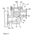
- FIG. 2 A possible modification to the non-return valve 10 is shown in Figure 2.
- the modification comprises the provision of a compression spring 40 between the ball 18 and the plate 22.
- the spring 40 is arranged to bias the ball to a position in which it engages the valve seat 16 defined by the O-ring.
- spring can be selected such that the ball will not lift from the valve seat until the pressure of the gas/vapour in the inlet side 14i of the through-passage at least reaches a predetermined threshold and the presence of the spring will ensure that if the pressure in the inlet side falls below that threshold pressure, the ball will promptly be pressed back against the valve seat to prevent the backflow of gas/vapour from the outlet side 14e to the inlet side 14i.
- a vacuum pump non-return valve comprises a valve body (12) that defines a through-passage having an inlet side (14i) and an outlet side (14e).
- a valve seat (16) is disposed intermediate said inlet and outlet sides of the through-passage.
- the valve seat (16) is defined by an insert made of an elastomeric material.
- the non-return valve has a ball (18) arranged to seat against the valve seat to prevent the passage of gaseous fluids from the outlet side (14e) to the inlet side (14i).
- the ball is displaceable, in use, from the valve seat by pressurised gaseous fluid in the inlet side of the through-passage to permit passage of gaseous fluid from the inlet side to the outlet side of the through-passage.
Landscapes
- Engineering & Computer Science (AREA)
- General Engineering & Computer Science (AREA)
- Mechanical Engineering (AREA)
- Check Valves (AREA)
- Taps Or Cocks (AREA)
Applications Claiming Priority (4)
| Application Number | Priority Date | Filing Date | Title |
|---|---|---|---|
| GB0221918A GB0221918D0 (en) | 2002-09-20 | 2002-09-20 | Non-return valves for vacuum pumps |
| GB0221918 | 2002-09-20 | ||
| GB0321051 | 2003-09-08 | ||
| GB0321051A GB0321051D0 (en) | 2003-09-08 | 2003-09-08 | Non-return valves for vacuum pumps |
Publications (1)
| Publication Number | Publication Date |
|---|---|
| EP1400690A2 true EP1400690A2 (de) | 2004-03-24 |
Family
ID=31948046
Family Applications (1)
| Application Number | Title | Priority Date | Filing Date |
|---|---|---|---|
| EP03255709A Withdrawn EP1400690A2 (de) | 2002-09-20 | 2003-09-12 | Rückschlagventil für Vakuumpumpen |
Country Status (4)
| Country | Link |
|---|---|
| US (1) | US20040120838A1 (de) |
| EP (1) | EP1400690A2 (de) |
| JP (1) | JP3100586U (de) |
| DE (1) | DE20314499U1 (de) |
Cited By (2)
| Publication number | Priority date | Publication date | Assignee | Title |
|---|---|---|---|---|
| FR2899947A1 (fr) * | 2006-04-18 | 2007-10-19 | Jeantet Elastomeres Sa | Element d'obturation pour la regulation de la circulation d'un fluide dans une installation hydraulique |
| EP2363606A3 (de) * | 2009-05-18 | 2012-07-18 | Borsig Compressor Parts GmbH | Kompressorventil zum Steuern einer Kolbenmaschine |
Families Citing this family (5)
| Publication number | Priority date | Publication date | Assignee | Title |
|---|---|---|---|---|
| JP4611673B2 (ja) * | 2004-06-28 | 2011-01-12 | 藤倉ゴム工業株式会社 | リリーフ弁およびその製造方法 |
| EP3374637B1 (de) * | 2015-11-11 | 2021-03-17 | Graco Minnesota Inc. | Kugelkäfig mit gerichteten strömungswegen für eine kugelpumpe |
| US11572876B2 (en) | 2017-08-30 | 2023-02-07 | Graco Minnesota Inc. | Pump piston |
| KR102321303B1 (ko) * | 2020-05-15 | 2021-11-02 | 주식회사 포스코 | 압력조절밸브 |
| CN117396693A (zh) * | 2021-05-26 | 2024-01-12 | 沃特世科技公司 | 具有球形加载元件的止回阀 |
Family Cites Families (10)
| Publication number | Priority date | Publication date | Assignee | Title |
|---|---|---|---|---|
| US3346008A (en) * | 1964-03-16 | 1967-10-10 | Scaramucci Domer | Ball check valve |
| US4781213A (en) * | 1987-11-16 | 1988-11-01 | Kilayko Enrique L | Ball check valve |
| US5243816A (en) * | 1992-06-19 | 1993-09-14 | Fuel Systems Textron, Inc. | Self purging fuel injector |
| US5370507A (en) * | 1993-01-25 | 1994-12-06 | Trebor Incorporated | Reciprocating chemical pumps |
| US5478216A (en) * | 1993-09-08 | 1995-12-26 | Neward; Theodore C. | Vacuum limiter for pump |
| US5542450A (en) * | 1994-06-10 | 1996-08-06 | The Lubrizol Corporation | Apparatus for metering fluids |
| US5749394A (en) * | 1996-10-09 | 1998-05-12 | Vernay Laboratories, Inc. | Check valve including molded valve seat |
| US6165313A (en) * | 1999-04-14 | 2000-12-26 | Advanced Micro Devices, Inc. | Downstream plasma reactor system with an improved plasma tube sealing configuration |
| FR2807477B1 (fr) * | 2000-04-06 | 2002-07-12 | Cit Alcatel | Systeme de refroidissement de pompe a vide, et procede pour sa realisation |
| FR2815691B1 (fr) * | 2000-10-20 | 2003-08-15 | Valois Sa | Bille de clapet |
-
2003
- 2003-09-12 EP EP03255709A patent/EP1400690A2/de not_active Withdrawn
- 2003-09-17 DE DE20314499U patent/DE20314499U1/de not_active Expired - Lifetime
- 2003-09-17 US US10/664,335 patent/US20040120838A1/en not_active Abandoned
- 2003-09-22 JP JP2003271342U patent/JP3100586U/ja not_active Expired - Fee Related
Cited By (3)
| Publication number | Priority date | Publication date | Assignee | Title |
|---|---|---|---|---|
| FR2899947A1 (fr) * | 2006-04-18 | 2007-10-19 | Jeantet Elastomeres Sa | Element d'obturation pour la regulation de la circulation d'un fluide dans une installation hydraulique |
| WO2007118951A1 (fr) * | 2006-04-18 | 2007-10-25 | Jeantet Elastomeres Sa | Element d'obturation pour la regulation de la circulation d'un fluide dans une installation hydraulique |
| EP2363606A3 (de) * | 2009-05-18 | 2012-07-18 | Borsig Compressor Parts GmbH | Kompressorventil zum Steuern einer Kolbenmaschine |
Also Published As
| Publication number | Publication date |
|---|---|
| DE20314499U1 (de) | 2004-03-11 |
| JP3100586U (ja) | 2004-05-20 |
| US20040120838A1 (en) | 2004-06-24 |
Similar Documents
| Publication | Publication Date | Title |
|---|---|---|
| EP1596107B1 (de) | Membranventil für vakuumevakuierungssystem | |
| US7988130B2 (en) | Valve for vacuum exhaustion system | |
| US20190316685A1 (en) | Pump valve with seal retaining structure | |
| US7481238B2 (en) | Automatic degassing valve | |
| JPH07167307A (ja) | 取外し可能な加熱式絞り弁 | |
| EP1400690A2 (de) | Rückschlagventil für Vakuumpumpen | |
| US20070056636A1 (en) | Spring actuated check valve | |
| CN112105855B (zh) | 球式止回阀以及隔膜泵 | |
| US20170298601A1 (en) | Anti-air lock negative and/or vacuum pressure air admittance connector | |
| JP2009527712A (ja) | シール | |
| JP2007526975A (ja) | 流体を受け取りかつ排出するシールコーティングを有する装置 | |
| JP4237032B2 (ja) | 開閉弁及びこれを用いた半導体製造設備用排気装置 | |
| US10794505B2 (en) | Spring seat for an internal valve | |
| US20230296183A1 (en) | Non-return check valve and check valve apparatus for vacuum system | |
| JP2005140260A (ja) | 真空比例開閉弁 | |
| JP6944178B2 (ja) | バルブ | |
| JP2005140295A (ja) | 制御弁の分解方法及びそれに使用する制御弁 | |
| DE60334851D1 (de) | Ventil, insbesondere für ein turboladersystem | |
| JP2008103754A (ja) | 真空排気系用バルブの使用方法 | |
| JP2009138817A (ja) | 弁構造 | |
| JPH09324865A (ja) | フラッシュバルブ |
Legal Events
| Date | Code | Title | Description |
|---|---|---|---|
| PUAI | Public reference made under article 153(3) epc to a published international application that has entered the european phase |
Free format text: ORIGINAL CODE: 0009012 |
|
| AK | Designated contracting states |
Kind code of ref document: A2 Designated state(s): AT BE BG CH CY CZ DE DK EE ES FI FR GB GR HU IE IT LI LU MC NL PT RO SE SI SK TR |
|
| AX | Request for extension of the european patent |
Extension state: AL LT LV MK |
|
| STAA | Information on the status of an ep patent application or granted ep patent |
Free format text: STATUS: THE APPLICATION HAS BEEN WITHDRAWN |
|
| 18W | Application withdrawn |
Effective date: 20060721 |