EP1400664A1 - Verfahren und Vorrichtung zur Reinigung von Abgas - Google Patents
Verfahren und Vorrichtung zur Reinigung von Abgas Download PDFInfo
- Publication number
- EP1400664A1 EP1400664A1 EP03020642A EP03020642A EP1400664A1 EP 1400664 A1 EP1400664 A1 EP 1400664A1 EP 03020642 A EP03020642 A EP 03020642A EP 03020642 A EP03020642 A EP 03020642A EP 1400664 A1 EP1400664 A1 EP 1400664A1
- Authority
- EP
- European Patent Office
- Prior art keywords
- exhaust gas
- gas purifying
- temperature
- accumulated
- hydrocarbon
- Prior art date
- Legal status (The legal status is an assumption and is not a legal conclusion. Google has not performed a legal analysis and makes no representation as to the accuracy of the status listed.)
- Granted
Links
Images


Classifications
-
- B—PERFORMING OPERATIONS; TRANSPORTING
- B01—PHYSICAL OR CHEMICAL PROCESSES OR APPARATUS IN GENERAL
- B01D—SEPARATION
- B01D53/00—Separation of gases or vapours; Recovering vapours of volatile solvents from gases; Chemical or biological purification of waste gases, e.g. engine exhaust gases, smoke, fumes, flue gases, aerosols
- B01D53/34—Chemical or biological purification of waste gases
- B01D53/92—Chemical or biological purification of waste gases of engine exhaust gases
- B01D53/94—Chemical or biological purification of waste gases of engine exhaust gases by catalytic processes
- B01D53/9445—Simultaneously removing carbon monoxide, hydrocarbons or nitrogen oxides making use of three-way catalysts [TWC] or four-way-catalysts [FWC]
- B01D53/9454—Simultaneously removing carbon monoxide, hydrocarbons or nitrogen oxides making use of three-way catalysts [TWC] or four-way-catalysts [FWC] characterised by a specific device
-
- B—PERFORMING OPERATIONS; TRANSPORTING
- B01—PHYSICAL OR CHEMICAL PROCESSES OR APPARATUS IN GENERAL
- B01D—SEPARATION
- B01D53/00—Separation of gases or vapours; Recovering vapours of volatile solvents from gases; Chemical or biological purification of waste gases, e.g. engine exhaust gases, smoke, fumes, flue gases, aerosols
- B01D53/34—Chemical or biological purification of waste gases
- B01D53/92—Chemical or biological purification of waste gases of engine exhaust gases
- B01D53/94—Chemical or biological purification of waste gases of engine exhaust gases by catalytic processes
- B01D53/944—Simultaneously removing carbon monoxide, hydrocarbons or carbon making use of oxidation catalysts
-
- B—PERFORMING OPERATIONS; TRANSPORTING
- B01—PHYSICAL OR CHEMICAL PROCESSES OR APPARATUS IN GENERAL
- B01D—SEPARATION
- B01D53/00—Separation of gases or vapours; Recovering vapours of volatile solvents from gases; Chemical or biological purification of waste gases, e.g. engine exhaust gases, smoke, fumes, flue gases, aerosols
- B01D53/34—Chemical or biological purification of waste gases
- B01D53/92—Chemical or biological purification of waste gases of engine exhaust gases
- B01D53/94—Chemical or biological purification of waste gases of engine exhaust gases by catalytic processes
- B01D53/9495—Controlling the catalytic process
-
- F—MECHANICAL ENGINEERING; LIGHTING; HEATING; WEAPONS; BLASTING
- F01—MACHINES OR ENGINES IN GENERAL; ENGINE PLANTS IN GENERAL; STEAM ENGINES
- F01N—GAS-FLOW SILENCERS OR EXHAUST APPARATUS FOR MACHINES OR ENGINES IN GENERAL; GAS-FLOW SILENCERS OR EXHAUST APPARATUS FOR INTERNAL COMBUSTION ENGINES
- F01N13/00—Exhaust or silencing apparatus characterised by constructional features ; Exhaust or silencing apparatus, or parts thereof, having pertinent characteristics not provided for in, or of interest apart from, groups F01N1/00 - F01N5/00, F01N9/00, F01N11/00
- F01N13/009—Exhaust or silencing apparatus characterised by constructional features ; Exhaust or silencing apparatus, or parts thereof, having pertinent characteristics not provided for in, or of interest apart from, groups F01N1/00 - F01N5/00, F01N9/00, F01N11/00 having two or more separate purifying devices arranged in series
- F01N13/0097—Exhaust or silencing apparatus characterised by constructional features ; Exhaust or silencing apparatus, or parts thereof, having pertinent characteristics not provided for in, or of interest apart from, groups F01N1/00 - F01N5/00, F01N9/00, F01N11/00 having two or more separate purifying devices arranged in series the purifying devices are arranged in a single housing
-
- F—MECHANICAL ENGINEERING; LIGHTING; HEATING; WEAPONS; BLASTING
- F01—MACHINES OR ENGINES IN GENERAL; ENGINE PLANTS IN GENERAL; STEAM ENGINES
- F01N—GAS-FLOW SILENCERS OR EXHAUST APPARATUS FOR MACHINES OR ENGINES IN GENERAL; GAS-FLOW SILENCERS OR EXHAUST APPARATUS FOR INTERNAL COMBUSTION ENGINES
- F01N3/00—Exhaust or silencing apparatus having means for purifying, rendering innocuous, or otherwise treating exhaust
- F01N3/02—Exhaust or silencing apparatus having means for purifying, rendering innocuous, or otherwise treating exhaust for cooling, or for removing solid constituents of, exhaust
- F01N3/021—Exhaust or silencing apparatus having means for purifying, rendering innocuous, or otherwise treating exhaust for cooling, or for removing solid constituents of, exhaust by means of filters
- F01N3/023—Exhaust or silencing apparatus having means for purifying, rendering innocuous, or otherwise treating exhaust for cooling, or for removing solid constituents of, exhaust by means of filters using means for regenerating the filters, e.g. by burning trapped particles
- F01N3/0231—Exhaust or silencing apparatus having means for purifying, rendering innocuous, or otherwise treating exhaust for cooling, or for removing solid constituents of, exhaust by means of filters using means for regenerating the filters, e.g. by burning trapped particles using special exhaust apparatus upstream of the filter for producing nitrogen dioxide, e.g. for continuous filter regeneration systems [CRT]
-
- F—MECHANICAL ENGINEERING; LIGHTING; HEATING; WEAPONS; BLASTING
- F01—MACHINES OR ENGINES IN GENERAL; ENGINE PLANTS IN GENERAL; STEAM ENGINES
- F01N—GAS-FLOW SILENCERS OR EXHAUST APPARATUS FOR MACHINES OR ENGINES IN GENERAL; GAS-FLOW SILENCERS OR EXHAUST APPARATUS FOR INTERNAL COMBUSTION ENGINES
- F01N3/00—Exhaust or silencing apparatus having means for purifying, rendering innocuous, or otherwise treating exhaust
- F01N3/08—Exhaust or silencing apparatus having means for purifying, rendering innocuous, or otherwise treating exhaust for rendering innocuous
- F01N3/0807—Exhaust or silencing apparatus having means for purifying, rendering innocuous, or otherwise treating exhaust for rendering innocuous by using absorbents or adsorbents
- F01N3/0828—Exhaust or silencing apparatus having means for purifying, rendering innocuous, or otherwise treating exhaust for rendering innocuous by using absorbents or adsorbents characterised by the absorbed or adsorbed substances
- F01N3/0835—Hydrocarbons
-
- F—MECHANICAL ENGINEERING; LIGHTING; HEATING; WEAPONS; BLASTING
- F01—MACHINES OR ENGINES IN GENERAL; ENGINE PLANTS IN GENERAL; STEAM ENGINES
- F01N—GAS-FLOW SILENCERS OR EXHAUST APPARATUS FOR MACHINES OR ENGINES IN GENERAL; GAS-FLOW SILENCERS OR EXHAUST APPARATUS FOR INTERNAL COMBUSTION ENGINES
- F01N3/00—Exhaust or silencing apparatus having means for purifying, rendering innocuous, or otherwise treating exhaust
- F01N3/08—Exhaust or silencing apparatus having means for purifying, rendering innocuous, or otherwise treating exhaust for rendering innocuous
- F01N3/0807—Exhaust or silencing apparatus having means for purifying, rendering innocuous, or otherwise treating exhaust for rendering innocuous by using absorbents or adsorbents
- F01N3/0871—Regulation of absorbents or adsorbents, e.g. purging
-
- F—MECHANICAL ENGINEERING; LIGHTING; HEATING; WEAPONS; BLASTING
- F02—COMBUSTION ENGINES; HOT-GAS OR COMBUSTION-PRODUCT ENGINE PLANTS
- F02D—CONTROLLING COMBUSTION ENGINES
- F02D41/00—Electrical control of supply of combustible mixture or its constituents
- F02D41/02—Circuit arrangements for generating control signals
- F02D41/021—Introducing corrections for particular conditions exterior to the engine
- F02D41/0235—Introducing corrections for particular conditions exterior to the engine in relation with the state of the exhaust gas treating apparatus
- F02D41/027—Introducing corrections for particular conditions exterior to the engine in relation with the state of the exhaust gas treating apparatus to purge or regenerate the exhaust gas treating apparatus
- F02D41/029—Introducing corrections for particular conditions exterior to the engine in relation with the state of the exhaust gas treating apparatus to purge or regenerate the exhaust gas treating apparatus the exhaust gas treating apparatus being a particulate filter
-
- F—MECHANICAL ENGINEERING; LIGHTING; HEATING; WEAPONS; BLASTING
- F02—COMBUSTION ENGINES; HOT-GAS OR COMBUSTION-PRODUCT ENGINE PLANTS
- F02D—CONTROLLING COMBUSTION ENGINES
- F02D41/00—Electrical control of supply of combustible mixture or its constituents
- F02D41/02—Circuit arrangements for generating control signals
- F02D41/14—Introducing closed-loop corrections
- F02D41/1438—Introducing closed-loop corrections using means for determining characteristics of the combustion gases; Sensors therefor
- F02D41/1444—Introducing closed-loop corrections using means for determining characteristics of the combustion gases; Sensors therefor characterised by the characteristics of the combustion gases
- F02D41/1448—Introducing closed-loop corrections using means for determining characteristics of the combustion gases; Sensors therefor characterised by the characteristics of the combustion gases the characteristics being an exhaust gas pressure
-
- F—MECHANICAL ENGINEERING; LIGHTING; HEATING; WEAPONS; BLASTING
- F02—COMBUSTION ENGINES; HOT-GAS OR COMBUSTION-PRODUCT ENGINE PLANTS
- F02D—CONTROLLING COMBUSTION ENGINES
- F02D41/00—Electrical control of supply of combustible mixture or its constituents
- F02D41/30—Controlling fuel injection
- F02D41/38—Controlling fuel injection of the high pressure type
- F02D41/40—Controlling fuel injection of the high pressure type with means for controlling injection timing or duration
- F02D41/402—Multiple injections
- F02D41/403—Multiple injections with pilot injections
-
- B—PERFORMING OPERATIONS; TRANSPORTING
- B01—PHYSICAL OR CHEMICAL PROCESSES OR APPARATUS IN GENERAL
- B01D—SEPARATION
- B01D2255/00—Catalysts
- B01D2255/90—Physical characteristics of catalysts
- B01D2255/912—HC-storage component incorporated in the catalyst
-
- F—MECHANICAL ENGINEERING; LIGHTING; HEATING; WEAPONS; BLASTING
- F01—MACHINES OR ENGINES IN GENERAL; ENGINE PLANTS IN GENERAL; STEAM ENGINES
- F01N—GAS-FLOW SILENCERS OR EXHAUST APPARATUS FOR MACHINES OR ENGINES IN GENERAL; GAS-FLOW SILENCERS OR EXHAUST APPARATUS FOR INTERNAL COMBUSTION ENGINES
- F01N2250/00—Combinations of different methods of purification
- F01N2250/14—Combinations of different methods of purification absorption or adsorption, and filtering
-
- F—MECHANICAL ENGINEERING; LIGHTING; HEATING; WEAPONS; BLASTING
- F01—MACHINES OR ENGINES IN GENERAL; ENGINE PLANTS IN GENERAL; STEAM ENGINES
- F01N—GAS-FLOW SILENCERS OR EXHAUST APPARATUS FOR MACHINES OR ENGINES IN GENERAL; GAS-FLOW SILENCERS OR EXHAUST APPARATUS FOR INTERNAL COMBUSTION ENGINES
- F01N2330/00—Structure of catalyst support or particle filter
- F01N2330/06—Ceramic, e.g. monoliths
-
- F—MECHANICAL ENGINEERING; LIGHTING; HEATING; WEAPONS; BLASTING
- F01—MACHINES OR ENGINES IN GENERAL; ENGINE PLANTS IN GENERAL; STEAM ENGINES
- F01N—GAS-FLOW SILENCERS OR EXHAUST APPARATUS FOR MACHINES OR ENGINES IN GENERAL; GAS-FLOW SILENCERS OR EXHAUST APPARATUS FOR INTERNAL COMBUSTION ENGINES
- F01N2330/00—Structure of catalyst support or particle filter
- F01N2330/10—Fibrous material, e.g. mineral or metallic wool
-
- F—MECHANICAL ENGINEERING; LIGHTING; HEATING; WEAPONS; BLASTING
- F01—MACHINES OR ENGINES IN GENERAL; ENGINE PLANTS IN GENERAL; STEAM ENGINES
- F01N—GAS-FLOW SILENCERS OR EXHAUST APPARATUS FOR MACHINES OR ENGINES IN GENERAL; GAS-FLOW SILENCERS OR EXHAUST APPARATUS FOR INTERNAL COMBUSTION ENGINES
- F01N2430/00—Influencing exhaust purification, e.g. starting of catalytic reaction, filter regeneration, or the like, by controlling engine operating characteristics
- F01N2430/06—Influencing exhaust purification, e.g. starting of catalytic reaction, filter regeneration, or the like, by controlling engine operating characteristics by varying fuel-air ratio, e.g. by enriching fuel-air mixture
-
- F—MECHANICAL ENGINEERING; LIGHTING; HEATING; WEAPONS; BLASTING
- F01—MACHINES OR ENGINES IN GENERAL; ENGINE PLANTS IN GENERAL; STEAM ENGINES
- F01N—GAS-FLOW SILENCERS OR EXHAUST APPARATUS FOR MACHINES OR ENGINES IN GENERAL; GAS-FLOW SILENCERS OR EXHAUST APPARATUS FOR INTERNAL COMBUSTION ENGINES
- F01N2430/00—Influencing exhaust purification, e.g. starting of catalytic reaction, filter regeneration, or the like, by controlling engine operating characteristics
- F01N2430/08—Influencing exhaust purification, e.g. starting of catalytic reaction, filter regeneration, or the like, by controlling engine operating characteristics by modifying ignition or injection timing
- F01N2430/085—Influencing exhaust purification, e.g. starting of catalytic reaction, filter regeneration, or the like, by controlling engine operating characteristics by modifying ignition or injection timing at least a part of the injection taking place during expansion or exhaust stroke
-
- F—MECHANICAL ENGINEERING; LIGHTING; HEATING; WEAPONS; BLASTING
- F01—MACHINES OR ENGINES IN GENERAL; ENGINE PLANTS IN GENERAL; STEAM ENGINES
- F01N—GAS-FLOW SILENCERS OR EXHAUST APPARATUS FOR MACHINES OR ENGINES IN GENERAL; GAS-FLOW SILENCERS OR EXHAUST APPARATUS FOR INTERNAL COMBUSTION ENGINES
- F01N2510/00—Surface coverings
- F01N2510/06—Surface coverings for exhaust purification, e.g. catalytic reaction
- F01N2510/065—Surface coverings for exhaust purification, e.g. catalytic reaction for reducing soot ignition temperature
-
- F—MECHANICAL ENGINEERING; LIGHTING; HEATING; WEAPONS; BLASTING
- F01—MACHINES OR ENGINES IN GENERAL; ENGINE PLANTS IN GENERAL; STEAM ENGINES
- F01N—GAS-FLOW SILENCERS OR EXHAUST APPARATUS FOR MACHINES OR ENGINES IN GENERAL; GAS-FLOW SILENCERS OR EXHAUST APPARATUS FOR INTERNAL COMBUSTION ENGINES
- F01N2550/00—Monitoring or diagnosing the deterioration of exhaust systems
- F01N2550/03—Monitoring or diagnosing the deterioration of exhaust systems of sorbing activity of adsorbents or absorbents
-
- F—MECHANICAL ENGINEERING; LIGHTING; HEATING; WEAPONS; BLASTING
- F01—MACHINES OR ENGINES IN GENERAL; ENGINE PLANTS IN GENERAL; STEAM ENGINES
- F01N—GAS-FLOW SILENCERS OR EXHAUST APPARATUS FOR MACHINES OR ENGINES IN GENERAL; GAS-FLOW SILENCERS OR EXHAUST APPARATUS FOR INTERNAL COMBUSTION ENGINES
- F01N3/00—Exhaust or silencing apparatus having means for purifying, rendering innocuous, or otherwise treating exhaust
- F01N3/08—Exhaust or silencing apparatus having means for purifying, rendering innocuous, or otherwise treating exhaust for rendering innocuous
- F01N3/0807—Exhaust or silencing apparatus having means for purifying, rendering innocuous, or otherwise treating exhaust for rendering innocuous by using absorbents or adsorbents
- F01N3/0821—Exhaust or silencing apparatus having means for purifying, rendering innocuous, or otherwise treating exhaust for rendering innocuous by using absorbents or adsorbents combined with particulate filters
-
- F—MECHANICAL ENGINEERING; LIGHTING; HEATING; WEAPONS; BLASTING
- F01—MACHINES OR ENGINES IN GENERAL; ENGINE PLANTS IN GENERAL; STEAM ENGINES
- F01N—GAS-FLOW SILENCERS OR EXHAUST APPARATUS FOR MACHINES OR ENGINES IN GENERAL; GAS-FLOW SILENCERS OR EXHAUST APPARATUS FOR INTERNAL COMBUSTION ENGINES
- F01N9/00—Electrical control of exhaust gas treating apparatus
- F01N9/002—Electrical control of exhaust gas treating apparatus of filter regeneration, e.g. detection of clogging
-
- F—MECHANICAL ENGINEERING; LIGHTING; HEATING; WEAPONS; BLASTING
- F02—COMBUSTION ENGINES; HOT-GAS OR COMBUSTION-PRODUCT ENGINE PLANTS
- F02D—CONTROLLING COMBUSTION ENGINES
- F02D2200/00—Input parameters for engine control
- F02D2200/02—Input parameters for engine control the parameters being related to the engine
- F02D2200/04—Engine intake system parameters
- F02D2200/0404—Throttle position
-
- F—MECHANICAL ENGINEERING; LIGHTING; HEATING; WEAPONS; BLASTING
- F02—COMBUSTION ENGINES; HOT-GAS OR COMBUSTION-PRODUCT ENGINE PLANTS
- F02D—CONTROLLING COMBUSTION ENGINES
- F02D2200/00—Input parameters for engine control
- F02D2200/02—Input parameters for engine control the parameters being related to the engine
- F02D2200/08—Exhaust gas treatment apparatus parameters
- F02D2200/0802—Temperature of the exhaust gas treatment apparatus
-
- F—MECHANICAL ENGINEERING; LIGHTING; HEATING; WEAPONS; BLASTING
- F02—COMBUSTION ENGINES; HOT-GAS OR COMBUSTION-PRODUCT ENGINE PLANTS
- F02D—CONTROLLING COMBUSTION ENGINES
- F02D2200/00—Input parameters for engine control
- F02D2200/50—Input parameters for engine control said parameters being related to the vehicle or its components
- F02D2200/501—Vehicle speed
-
- F—MECHANICAL ENGINEERING; LIGHTING; HEATING; WEAPONS; BLASTING
- F02—COMBUSTION ENGINES; HOT-GAS OR COMBUSTION-PRODUCT ENGINE PLANTS
- F02D—CONTROLLING COMBUSTION ENGINES
- F02D41/00—Electrical control of supply of combustible mixture or its constituents
- F02D41/30—Controlling fuel injection
- F02D41/38—Controlling fuel injection of the high pressure type
- F02D41/40—Controlling fuel injection of the high pressure type with means for controlling injection timing or duration
- F02D41/402—Multiple injections
-
- F—MECHANICAL ENGINEERING; LIGHTING; HEATING; WEAPONS; BLASTING
- F02—COMBUSTION ENGINES; HOT-GAS OR COMBUSTION-PRODUCT ENGINE PLANTS
- F02M—SUPPLYING COMBUSTION ENGINES IN GENERAL WITH COMBUSTIBLE MIXTURES OR CONSTITUENTS THEREOF
- F02M26/00—Engine-pertinent apparatus for adding exhaust gases to combustion-air, main fuel or fuel-air mixture, e.g. by exhaust gas recirculation [EGR] systems
- F02M26/13—Arrangement or layout of EGR passages, e.g. in relation to specific engine parts or for incorporation of accessories
-
- Y—GENERAL TAGGING OF NEW TECHNOLOGICAL DEVELOPMENTS; GENERAL TAGGING OF CROSS-SECTIONAL TECHNOLOGIES SPANNING OVER SEVERAL SECTIONS OF THE IPC; TECHNICAL SUBJECTS COVERED BY FORMER USPC CROSS-REFERENCE ART COLLECTIONS [XRACs] AND DIGESTS
- Y02—TECHNOLOGIES OR APPLICATIONS FOR MITIGATION OR ADAPTATION AGAINST CLIMATE CHANGE
- Y02T—CLIMATE CHANGE MITIGATION TECHNOLOGIES RELATED TO TRANSPORTATION
- Y02T10/00—Road transport of goods or passengers
- Y02T10/10—Internal combustion engine [ICE] based vehicles
- Y02T10/12—Improving ICE efficiencies
-
- Y—GENERAL TAGGING OF NEW TECHNOLOGICAL DEVELOPMENTS; GENERAL TAGGING OF CROSS-SECTIONAL TECHNOLOGIES SPANNING OVER SEVERAL SECTIONS OF THE IPC; TECHNICAL SUBJECTS COVERED BY FORMER USPC CROSS-REFERENCE ART COLLECTIONS [XRACs] AND DIGESTS
- Y02—TECHNOLOGIES OR APPLICATIONS FOR MITIGATION OR ADAPTATION AGAINST CLIMATE CHANGE
- Y02T—CLIMATE CHANGE MITIGATION TECHNOLOGIES RELATED TO TRANSPORTATION
- Y02T10/00—Road transport of goods or passengers
- Y02T10/10—Internal combustion engine [ICE] based vehicles
- Y02T10/40—Engine management systems
Definitions
- the present invention relates to an exhaust gas purifying method and an exhaust gas purifying system for purifying the exhaust gas of an internal combustion engine by using an oxidation catalyst. More particularly, the present invention relates to an exhaust gas purifying method and an exhaust gas purifying system capable of preventing an unburnt hydrocarbon accumulated in an oxidation catalyst due to a long-time idling operation from being exhausted into the atmosphere.
- the quantity of a particulate matter (hereafter referred to as PM) exhausted from a diesel internal combustion engine has been more strictly regulated year by year together with NOx, CO, and HC. Therefore, a technique has been developed which reduces the quantity of PM to be exhausted to the outside of the system by collecting the PM with a filter referred to as a diesel particulate filter (hereafter referred to as DPF).
- DPF diesel particulate filter
- a PM-collecting DPF includes a ceramic such types as a monolith-honeycomb wall-flow filter and a fibrous filter formed by fibrous ceramic or metal.
- An exhaust gas purifying system using one of these DPFs is set in the middle of the exhaust passage of an internal combustion engine the same as the case of other exhaust gas purifying systems to purify and exhaust the exhaust gas produced in the internal combustion engine.
- DPF systems include a continuous regenerating DPF type referred to as a CRT (Continuously Regenerating Trap) provided with an oxidation catalyst (DOC: Diesel Oxidation Catalyst) on the upstream side of a DPF system and a DPF type referred to as a CSF (Catalyst Soot Filter) for burning PM with an exhaust gas by lowering the combustion temperature of the PM in accordance with the action of a catalyst carried by a filter.
- CTR Continuous Regenerating Trap
- DOC Diesel Oxidation Catalyst
- CSF Catalyst Soot Filter
- the CRT-type continuous regenerating DPF system uses the fact that PM is oxidized with NO 2 (nitrogen dioxide) at a lower temperature than oxidizing the PM with oxygen in an exhaust gas, which is constituted of an oxidation catalyst and a filter.
- the PM is removed by oxidizing NO (nitrogen monoxide) in an exhaust gas to produce NO 2 on the upstream-side oxidation catalyst carrying platinum and oxidizing the PM collected in a downstream-side filter with the NO 2 to produce CO 2 (carbon dioxide).
- the CSF-type continuous regenerating DPF system is constituted of a catalyst-provided filter with such a catalyst as cerium oxide (CeO 2 ). Furthermore, at a low temperature (300°C to 600°C), PM is oxidized utilizing a reaction such as (4CeO 2 +C ⁇ 2Ce 2 O 3 +CO 2 , 2CeO 3 +O 2 ⁇ 4CeO 2 ) using O 2 (oxygen) in the exhaust gas in the catalyst-provided filter.
- a reaction such as (4CeO 2 +C ⁇ 2Ce 2 O 3 +CO 2 , 2CeO 3 +O 2 ⁇ 4CeO 2 ) using O 2 (oxygen) in the exhaust gas in the catalyst-provided filter.
- O 2 oxygen
- PM is oxidized and removed by setting an oxidation catalyst on the upstream side of the system, oxidizing unburnt HC and CO in exhaust gas, and raising an exhaust gas temperature while preventing the HC and CO from being exhausted into the atmosphere.
- regeneration control for oxidizing and removing PM collected in a filter is performed by estimating a deposited PM quantity in accordance with the differential pressure between a upstream and a downstream of a DPF when regenerating the filter, changing the present operation state of an internal combustion engine to a regenerating-mode operation when the differential pressure exceeds a predetermined judgment value, and forcibly raising the exhaust temperature or increasing the quantity of NO or NO 2 .
- the present invention is made to solve the above problems and its object is to provide a exhaust gas purifying method and a exhaust gas purifying system capable of preventing white fume from being produced after a low-exhaust-temperature state of the idling operation or the like continues for a long time by raising an exhaust gas temperature when the estimated accumulated unburnt-HC quantity adsorbed by the oxidation catalyst carrier exceeds a predetermined judgment value and oxidizing and removing the HC on the oxidation catalyst in an exhaust gas purifying system having an oxidation catalyst on the exhaust passage of an internal combustion engine.
- the exhaust gas purifying method for achieving the above object is an exhaust gas purifying method for purifying the exhaust gas of an internal combustion engine in an exhaust gas purifying system provided with an oxidation catalyst, in which a quantity of unburnt hydrocarbon accumulated in an oxidation catalyst carrier is estimated, the oxidation catalyst is activated by performing a hydrocarbon removal control and thereby raising an exhaust gas temperature to activate the oxidation catalyst when an estimated accumulated unburnt hydrocarbon quantity exceeds a predetermined judgment value, and the accumulated unburnt hydrocarbon is oxidized to be removed.
- an exhaust gas purifying method of the present invention when the quantity of unburnt HC accumulated due to a long-time idling operation or a low-exhaust-temperature state of a small-load and low-engine-speed operation or the like increases, accumulated unburnt HC is oxidized and removed by an oxidation catalyst activated by performing a hydrocarbon removal control and forcibly raising an exhaust gas temperature. Therefore, a white fume produced during a high-load operation after a low-exhaust-temperature operation is prevented from being produced.
- the exhaust gas purifying method uses the catalyst action of an oxidation catalyst and a temperature of an exhaust gas is required to raise up equal to or higher than an activation temperature (approx. 250°C) for an oxidation catalyst, therefore an unburnt HC can be oxidized at a comparatively low energy.
- a low exhaust temperature state denotes an operation state at a low exhaust temperature in which unburnt HC is accumulated in an oxidation catalyst without being oxidized.
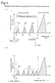
- the hydrocarbon removal control raises an exhaust gas temperature by performing a multistage fuel injection in an internal combustion engine. Thereby, it is not necessary to use another heating device such as an electric heater and it is possible to reduce the fuel cost without requiring a high energy produced by the electric heater.
- an exhaust gas purifying system for executing the above exhaust gas purifying method is an exhaust gas purifying system having an oxidation catalyst and purifying the exhaust gas of an internal combustion engine, which is constituted of an accumulated-hydrocarbon-quantity judgment means for estimating the quantity of unburnt hydrocarbon accumulated in the oxidation catalyst carrier and judging whether the estimated accumulation quantity of the unburnt hydrocarbon exceeds a predetermined judgment value and a hydrocarbon removal control means for activating the oxidation catalyst by raising an exhaust gas temperature to activate the oxidation catalyst when the accumulated-hydrocarbon-quantity judgment means judges that the estimated accumulation quantity exceeds the predetermined judgment value and oxidizing the accumulated unburnt hydrocarbon to remove.
- the accumulated-hydrocarbon-quantity judgment means judges whether an accumulated value of periods in which the internal combustion engine is kept in a low exhaust gas temperature state becomes a predetermined judgment value or more, instead of judging whether the estimated accumulation quantity of the unburnt hydrocarbon exceeds a predetermined judgment value.
- the hydrocarbon removal control means is constituted so as to perform a control for raising an exhaust gas temperature by performing a multistage fuel injection in an internal combustion engine.
- a continuous regenerating DPF system there are systems such as a system constituted by making a filter carry an oxidation catalyst, a system constituted by setting an oxidation catalyst to the upstream side of a filter, and a system constituted by making a filter carry a catalyst and setting an oxidation catalyst on the upstream side of a filter.
- an exhaust gas purifying method and an exhaust gas purifying system of the present invention make it possible to forcibly raise an exhaust gas temperature by performing an unburnt HC removal control when the quantity of unburnt HC accumulated in an oxidation catalyst increases affected by a low exhaust state of a long-time idling operation or low-load low-speed operation. Therefore, it is possible to oxidize and remove the accumulated unburnt HC by an oxidation catalyst heated and activated by a temperature-raised exhaust gas and to prevent a white fume produced during a high-load operation is started after a long-time low-exhaust-temperature operation from being produced.
- the exhaust gas purifying method and the exhaust gas purifying system use the catalyst action of an oxidation catalyst, it is possible to oxidize unburnt HC by a comparatively low energy. Therefore, it is only required to raise an exhaust gas temperature up to a temperature equal to or higher than an activation temperature (approx. 250°C) at which the oxidation catalyst is activated. Moreover, because the exhaust gas temperature is raised through a fuel injection control in an engine, another heating means such as a fuel electric heater is not required.
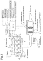
- Figs. 1 and 2 show a configuration of an exhaust gas purifying system 10 of an internal combustion engine of the above embodiment.
- the exhaust gas purifying system 10 of the internal combustion engine is constituted by including a continuous regenerating DPF system 3 which is set to an exhaust passage 2 connected to an exhaust manifold 13 of an engine (internal combustion engine) 1 and in which an oxidation catalyst 3a is set to the upstream side and a catalyst-provided filter 3b is set to the downstream side.
- the oxidation catalyst 3a is formed by making a porous ceramic carrier with such a structure as honeycomb type carry an oxidation catalyst such as platinum (Pt).
- the catalyst-provided filter 3b is formed by a monolith-honeycomb wall-flow filter obtained by alternately closing the inlet and outlet of a porous ceramic honeycomb channel or a pannose filter obtained by laminating inorganic fiber such as alumina at random.
- the filter portion carries a catalyst such as platinum or cerium oxide.
- a particulate matter (hereafter referred to as PM) contained in an exhaust gas is trapped by a porous ceramic wall.
- the PM is trapped by inorganic fiber of the filter.
- a differential-pressure sensor 6 is set to a conduction tube connected to the upstream and downstream of the continuous regenerating DPF system 3. Moreover, a temperature sensor 7 is set between the oxidation catalyst 3a and the catalyst-provided filter 3b for regeneration control of the catalyst-provided filter 3b.
- Outputs of these sensors are input to a controller (ECU: engine control unit) 5 which performs not only general control of operations of the engine 1 but also regeneration control of the catalyst-provided filter 3b.
- Control signals output from the controller 5 control a fuel injection system 4 of the engine 1, an intake valve 8 for adjusting an air quantity to be supplied to an intake manifold 12, and an EGR valve 9 for adjusting an EGR quantity.
- the fuel injection system 4 is connected to a common rail 41 for temporarily storing a high-pressure fuel boosted by a fuel pump 42.
- the controller 5 also receives the information on on/off of a PTO switch, on/off of a neutral switch, vehicle speed, cooling-water temperature Tw, engine speed Ne, and accelerator opening degree Q.
- an accumulated-HC-quantity judgment means (accumulated-hydrocarbon judgment means) 51C and HC removal control means (hydrocarbon removal control means) 51D are set to the DPF control means 51 of the controller 5 in addition to collected-PM-quantity estimation means 51A and regeneration control means 51B.
- the collected-PM-quantity estimation means 51A serves as means for estimating the PM quantity collected in the catalyst-provided filter 3b of the continuous regenerating DPF system 3.
- the collected PM quantity is estimated by using the differential pressure ⁇ P between the upstream and the downstream of the catalyst-provided filter 3b and relating the differential pressure ⁇ P with the collected PM quantity.
- the regeneration control means 51B is executed when the differential pressure ⁇ P is equal to or more than a predetermined regeneration judgment value ⁇ Pa.
- this means is slightly different in the way of controlling by the types of the continuous regenerating DPF system 3, it raises an exhaust gas temperature by delaying (retarding) the timing of the main fuel injection of the engine 1, performing a post fuel injection, or an intake throttling. Thereby, a temperature or an environment suitable for an oxidation and a removal of PM is realized to oxidize and remove the PM collected in the continuous regenerating DPF system 3.
- the accumulated-HC-quantity judgment means 51C serves as means for estimating the quantity of unburnt HC accumulated in the carrier of the oxidation catalyst 3a and judging whether the estimated accumulation quantity Vhc of the unburnt HC exceeds a predetermined judgment value Vhc0. This means judges whether the accumulated value of periods in which an internal combustion engine is kept in a low-exhaust-temperature state becomes a predetermined judgment value (accumulation time) tm1 or more, instead of judging whether the estimated accumulation quantity Vhc of the unburnt HC exceeds the predetermined judgment value Vhc0.
- the temperature of the exhaust gas passing through the oxidation catalyst 3a is measured by the temperature sensor 7.
- the accumulation time tm of the low exhaust gas temperature state in which the filter-inlet exhaust gas temperature T is lower than a predetermined temperature Tc is measured by a timer.
- the measured time tm exceeds a predetermined accumulation time tm1
- the estimated accumulation quantity Vhc of the unburnt HC exceeds the predetermined judgment value Vhc0.
- the predetermined temperature e.g.
- Tc is a temperature relating to a filter-inlet exhaust gas temperature Ts at which the temperature of the oxidation catalyst 3a becomes an activation temperature, which is decided by considering a relation between the temperature of the oxidation catalyst 3a and the filter-inlet exhaust gas temperature or a response speed for a control.
- the HC removal control means 51D raises the temperature of the exhaust gas when the accumulated-HC-quantity judgment means 51C judges that the estimated accumulation quantity of unburnt HC exceeds the predetermined judgment value Vhc0, continues a state in which the filter-inlet exhaust gas temperature T is higher than the predetermined temperature Tc for a predetermined judgment value (removal time) tm2 or longer and the oxidation catalyst 3a is activate, and the accumulated unburnt HC is oxidized to be removed.
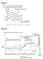
- the continuous regenerating DPF system 3 performs unburnt-HC related control in terms of an accumulation, an oxidation and a removal of an unburnt HC in the oxidation catalyst 3a in accordance with the flow shown in Fig. 4.
- the unburnt-HC related control is performed simultaneously with the normal filter-regenerating control for regenerating a filter when the collected-PM-quantity estimation means 51A or regeneration control means 51B judges that an estimated collected PM quantity exceeds a predetermined value.
- the accumulated-HC-quantity judgment means 51C judges an accumulated HC quantity first and then, the HC removal control means 51D removes the HC.
- step S11 When the unburnt-HC related control starts, judgment on an accumulated HC quantity is started and it is judged in step S11 whether the filter-inlet exhaust gas temperature T is lower than the predetermined temperature Tc.
- a timer operation is started in step S12, measurement of the accumulation time tm is started, and step S14 is started.
- the timer operation is stopped in step S13 to restart step S11.
- step S14 it is judged whether the accumulation time tm when the filter-inlet exhaust gas temperature T is lower than the predetermined temperature Tc exceeds the predetermined accumulation time tm1.
- step S11 is restarted to measure the accumulation time tm in which the filter-inlet exhaust gas temperature T is lower than the predetermined temperature Tc.
- the time tm exceeds the time tm1
- the timer is reset in step S15, and then the HC removal starts.
- an exhaust-gas-temperature-raising-control operation is executed in step S21.
- the exhaust-gas-temperature-raising-control operation is an operation for raising an exhaust gas temperature by performing an idling-up operation or multistage-fuel-injection-mode operation.
- the multistage-fuel-injection-mode operation is performed to raise the exhaust gas temperature.
- the multistage-fuel-injection-mode operation is performed to raise the exhaust gas temperature.
- the multistage-fuel-injection-mode operation is a fuel injection control operation capable of greatly raising an exhaust gas temperature even under an engine operating condition in which an exhaust gas temperature is low such as an idling operation or very low-load operation.
- a fuel injection control operation capable of greatly raising an exhaust gas temperature even under an engine operating condition in which an exhaust gas temperature is low such as an idling operation or very low-load operation.
- retarding the fuel injection period of the main fuel injection auxiliary fuel injection in the period before the main fuel injection period is performed twice or more in order to maintain a combustion flame up to the main fuel injection period.
- the auxiliary fuel injection is performed at multistage (e.g. three stages).
- An exhaust-gas-temperature-raising control operation is not restricted to the multistage fuel injection mode operation but it is allowed to use other fuel injection method or a method other than fuel injection. Moreover, it is possible to use a control same as the exhaust-gas-temperature-raising control in the regeneration control operation.
- step S22 it is judged whether the filter-inlet exhaust gas temperature T is lower than the predetermined temperature Tc.
- step S21 is restarted to repeat the exhaust-gas-temperature-control operation in step S21 until the temperature T becomes higher than the temperature Tc.
- step S23 an operation of the timer is started in step S23, measurement of the continuous time tm is started, and then an exhaust-gas-temperature-raising-control operation is performed in step S24 and step S25 is started.
- step S25 it is judged whether a continuous time tm' in which the filter-inlet exhaust gas temperature T is higher than the predetermined temperature Tc exceeds a predetermined removal time tm2.
- step S24 is restarted.
- the time tm' exceeds the time tm2 as a result of the above judgment, it is judged that removal of unburnt HC is completed to complete the exhaust-gas-temperature-raising-control operation in step S26 and the timer is reset in step S27 for return.
- the unburnt-HC removal control is called again and started to repeat steps S11 to S27.
- the repetition is performed while an internal combustion engine is operated to monitor accumulation of unburnt HC in the oxidation catalyst 3a and remove the unburnt HC.
Applications Claiming Priority (2)
| Application Number | Priority Date | Filing Date | Title |
|---|---|---|---|
| JP2002274750A JP2004108320A (ja) | 2002-09-20 | 2002-09-20 | 排気ガス浄化方法及びそのシステム |
| JP2002274750 | 2002-09-20 |
Publications (2)
| Publication Number | Publication Date |
|---|---|
| EP1400664A1 true EP1400664A1 (de) | 2004-03-24 |
| EP1400664B1 EP1400664B1 (de) | 2005-06-15 |
Family
ID=31944596
Family Applications (1)
| Application Number | Title | Priority Date | Filing Date |
|---|---|---|---|
| EP03020642A Expired - Fee Related EP1400664B1 (de) | 2002-09-20 | 2003-09-11 | Verfahren und Vorrichtung zur Reinigung von Abgas |
Country Status (4)
| Country | Link |
|---|---|
| US (1) | US7115237B2 (de) |
| EP (1) | EP1400664B1 (de) |
| JP (1) | JP2004108320A (de) |
| DE (1) | DE60300845T2 (de) |
Cited By (5)
| Publication number | Priority date | Publication date | Assignee | Title |
|---|---|---|---|---|
| EP1582710A1 (de) * | 2004-03-30 | 2005-10-05 | Isuzu Motors Limited | Verfahren und Vorrichtung zur Steuerung einer Abgasreinigungsanlage |
| US7115237B2 (en) * | 2002-09-20 | 2006-10-03 | Isuzu Motors Limited | Exhaust gas purifying method and exhaust gas purifying system |
| WO2010089038A1 (de) * | 2009-02-06 | 2010-08-12 | Daimler Ag | Verfahren zum betreiben einer brennkraftmaschine mit einer abgasreinigungsanlage |
| EP3112628A4 (de) * | 2014-02-28 | 2017-12-20 | Isuzu Motors Limited | Abgasreinigungsvorrichtung für einen verbrennungsmotor |
| GB2579079A (en) * | 2018-11-19 | 2020-06-10 | Perkins Engines Co Ltd | Method of controlling operation of an exhaust gas treatment apparatus |
Families Citing this family (19)
| Publication number | Priority date | Publication date | Assignee | Title |
|---|---|---|---|---|
| JP4049193B2 (ja) * | 2006-06-13 | 2008-02-20 | いすゞ自動車株式会社 | 排気ガス浄化システムの制御方法及び排気ガス浄化システム |
| JP4055808B2 (ja) | 2006-06-13 | 2008-03-05 | いすゞ自動車株式会社 | 排気ガス浄化システムの制御方法及び排気ガス浄化システム |
| DE102007046158B4 (de) * | 2007-09-27 | 2014-02-13 | Umicore Ag & Co. Kg | Verwendung eines katalytisch aktiven Partikelfilters zur Entfernung von Partikeln aus dem Abgas von mit überwiegend stöchiometrischem Luft/Kraftstoff-Gemisch betriebenen Verbrennungsmotoren |
| US20100050757A1 (en) * | 2008-08-28 | 2010-03-04 | Detroit Diesel Corporation | Method and system to determine the efficiency of a diesel oxidation catalyst |
| US8281571B2 (en) * | 2009-03-06 | 2012-10-09 | Detroit Diesel Corporation | Method for three zone diesel oxidation catalyst light off control system |
| US20110000193A1 (en) * | 2009-07-02 | 2011-01-06 | Woodward Governor Company | System and method for detecting diesel particulate filter conditions based on thermal response thereof |
| JP5348001B2 (ja) * | 2010-02-09 | 2013-11-20 | 三菱自動車工業株式会社 | 内燃機関の排気浄化装置 |
| US8857152B2 (en) * | 2010-12-21 | 2014-10-14 | GM Global Technology Operations LLC | System and method for unloading hydrocarbon emissions from an exhaust after-treatment device |
| DE102012211717A1 (de) * | 2012-07-05 | 2014-01-09 | Robert Bosch Gmbh | Verfahren zum Betreiben einer Abgasanlage für eine Brennkraftmaschine |
| US9003777B2 (en) | 2013-02-05 | 2015-04-14 | Ford Global Technologies, Llc | Methods and systems for an exhaust gas treatment system |
| JP6650675B2 (ja) * | 2014-02-26 | 2020-02-19 | エフピーティー インダストリアル エス ピー エー | 内燃機関の排気ガス後処理システムの管路内の未燃焼炭化水素の蓄積を防ぐシステム |
| DE102014214620A1 (de) * | 2014-07-25 | 2016-01-28 | Robert Bosch Gmbh | Vorrichtung zur Gasanalyse mit thermisch aktivierbarem Konversionselement |
| US10502136B2 (en) * | 2014-10-06 | 2019-12-10 | Bha Altair, Llc | Filtration system for use in a gas turbine engine assembly and method of assembling thereof |
| DE102014016447B4 (de) * | 2014-11-06 | 2023-05-11 | Andreas Döring | Verfahren und Steuerungseinrichtung zum Betreiben einer Brennkraftmaschine |
| GB2533376A (en) * | 2014-12-18 | 2016-06-22 | Gm Global Tech Operations Llc | A method of operating an internal combustion engine |
| JP6350505B2 (ja) * | 2015-12-14 | 2018-07-04 | 株式会社デンソー | 燃料噴射制御装置 |
| JP2019196735A (ja) * | 2018-05-09 | 2019-11-14 | ロベルト・ボッシュ・ゲゼルシャフト・ミト・ベシュレンクテル・ハフツングRobert Bosch Gmbh | 酸化触媒再生方法及び酸化触媒再生制御装置 |
| CN108825342B (zh) * | 2018-05-22 | 2019-09-24 | 庆铃汽车(集团)有限公司 | 一种消除发动机碳氢化合物沉积的控制方法 |
| CN108798920B (zh) * | 2018-06-29 | 2023-07-14 | 郑州精益达汽车零部件有限公司 | 一种主动喷油燃烧再生dpf控制策略 |
Citations (7)
| Publication number | Priority date | Publication date | Assignee | Title |
|---|---|---|---|---|
| US5772972A (en) * | 1995-01-09 | 1998-06-30 | Ford Global Technologies, Inc. | Catalyst/hydrocarbon trap hybrid system |
| US5887422A (en) * | 1992-12-06 | 1999-03-30 | Ngk Insulators, Ltd. | Exhaust gas purification method and apparatus therefor |
| EP0947236A1 (de) * | 1998-03-20 | 1999-10-06 | Engelhard Corporation | Katalisiertes Material für eine Kohlenwasserstofffalle und Verfahren zur Herstellung desselben |
| EP0980967A2 (de) * | 1998-08-19 | 2000-02-23 | Toyota Jidosha Kabushiki Kaisha | Katalysatorverschlechterungsdetektor und Verfahren zum Feststellen der Verschlechterung eines Katalysators |
| US6168764B1 (en) * | 1996-12-12 | 2001-01-02 | Daimlerchrysler Ag | Method and catalyst for reducing pollutants in gases |
| US6274107B1 (en) * | 1992-11-19 | 2001-08-14 | Engelhard Corporation | Zeolite-containing oxidation catalyst and method of use |
| US6334306B1 (en) * | 1998-05-29 | 2002-01-01 | Nissan Motor Co., Ltd. | Exhaust gas purification apparatus in combustion engine |
Family Cites Families (6)
| Publication number | Priority date | Publication date | Assignee | Title |
|---|---|---|---|---|
| US3872666A (en) * | 1972-10-04 | 1975-03-25 | Questor Corp | Method, system and apparatus for controlling temperatures of exhaust gases in emission control systems |
| US5451385A (en) * | 1991-08-01 | 1995-09-19 | Air Products And Chemicals, Inc. | Control of exhaust emissions from methane-fueled internal combustion engines |
| DE4208151C2 (de) * | 1992-03-13 | 1994-03-17 | Hench Automatik App Masch | Verfahren zur Verringerung der Betriebsmittelverschmutzung bei Vakuumpumpen bei der Reinigung von Abgasen, insbesondere aus Vakuumpyrolyseanlagen |
| JP3374782B2 (ja) * | 1999-04-28 | 2003-02-10 | トヨタ自動車株式会社 | 内燃機関の触媒劣化検出装置 |
| JP2000352303A (ja) | 1999-06-09 | 2000-12-19 | Isuzu Motors Ltd | エンジンの排気ガス浄化装置 |
| JP2004108320A (ja) * | 2002-09-20 | 2004-04-08 | Isuzu Motors Ltd | 排気ガス浄化方法及びそのシステム |
-
2002
- 2002-09-20 JP JP2002274750A patent/JP2004108320A/ja active Pending
-
2003
- 2003-09-11 DE DE60300845T patent/DE60300845T2/de not_active Expired - Lifetime
- 2003-09-11 US US10/659,252 patent/US7115237B2/en not_active Expired - Fee Related
- 2003-09-11 EP EP03020642A patent/EP1400664B1/de not_active Expired - Fee Related
Patent Citations (7)
| Publication number | Priority date | Publication date | Assignee | Title |
|---|---|---|---|---|
| US6274107B1 (en) * | 1992-11-19 | 2001-08-14 | Engelhard Corporation | Zeolite-containing oxidation catalyst and method of use |
| US5887422A (en) * | 1992-12-06 | 1999-03-30 | Ngk Insulators, Ltd. | Exhaust gas purification method and apparatus therefor |
| US5772972A (en) * | 1995-01-09 | 1998-06-30 | Ford Global Technologies, Inc. | Catalyst/hydrocarbon trap hybrid system |
| US6168764B1 (en) * | 1996-12-12 | 2001-01-02 | Daimlerchrysler Ag | Method and catalyst for reducing pollutants in gases |
| EP0947236A1 (de) * | 1998-03-20 | 1999-10-06 | Engelhard Corporation | Katalisiertes Material für eine Kohlenwasserstofffalle und Verfahren zur Herstellung desselben |
| US6334306B1 (en) * | 1998-05-29 | 2002-01-01 | Nissan Motor Co., Ltd. | Exhaust gas purification apparatus in combustion engine |
| EP0980967A2 (de) * | 1998-08-19 | 2000-02-23 | Toyota Jidosha Kabushiki Kaisha | Katalysatorverschlechterungsdetektor und Verfahren zum Feststellen der Verschlechterung eines Katalysators |
Cited By (10)
| Publication number | Priority date | Publication date | Assignee | Title |
|---|---|---|---|---|
| US7115237B2 (en) * | 2002-09-20 | 2006-10-03 | Isuzu Motors Limited | Exhaust gas purifying method and exhaust gas purifying system |
| EP1582710A1 (de) * | 2004-03-30 | 2005-10-05 | Isuzu Motors Limited | Verfahren und Vorrichtung zur Steuerung einer Abgasreinigungsanlage |
| WO2010089038A1 (de) * | 2009-02-06 | 2010-08-12 | Daimler Ag | Verfahren zum betreiben einer brennkraftmaschine mit einer abgasreinigungsanlage |
| RU2482309C1 (ru) * | 2009-02-06 | 2013-05-20 | Даймлер Аг | Способ для запуска двигателя внутреннего сгорания с установкой нейтрализации отработавших газов |
| US9322351B2 (en) | 2009-02-06 | 2016-04-26 | Daimler Ag | Method for operating an internal combustion engine with an emission control system |
| EP3112628A4 (de) * | 2014-02-28 | 2017-12-20 | Isuzu Motors Limited | Abgasreinigungsvorrichtung für einen verbrennungsmotor |
| US10054027B2 (en) | 2014-02-28 | 2018-08-21 | Isuzu Motors Limited | Exhaust purification apparatus for internal combustion engine |
| GB2579079A (en) * | 2018-11-19 | 2020-06-10 | Perkins Engines Co Ltd | Method of controlling operation of an exhaust gas treatment apparatus |
| GB2579079B (en) * | 2018-11-19 | 2021-05-19 | Perkins Engines Co Ltd | Method of controlling operation of an exhaust gas treatment apparatus |
| US11585251B2 (en) | 2018-11-19 | 2023-02-21 | Perkins Engines Company Limited | Method of controlling operation of an exhaust gas treatment apparatus |
Also Published As
| Publication number | Publication date |
|---|---|
| EP1400664B1 (de) | 2005-06-15 |
| US7115237B2 (en) | 2006-10-03 |
| DE60300845D1 (de) | 2005-07-21 |
| US20040105801A1 (en) | 2004-06-03 |
| JP2004108320A (ja) | 2004-04-08 |
| DE60300845T2 (de) | 2006-05-18 |
Similar Documents
| Publication | Publication Date | Title |
|---|---|---|
| EP1400664B1 (de) | Verfahren und Vorrichtung zur Reinigung von Abgas | |
| EP1905992B1 (de) | Verfahren zur steuerung eines abgasreinigungsystems und abgasreinigungssystem | |
| US7721534B2 (en) | Control method for an exhaust gas purification system and an exhaust gas purification system | |
| JP3933172B2 (ja) | 排気ガス浄化システムの制御方法及び排気ガス浄化システム | |
| US7086220B2 (en) | Regeneration control method for continuously regenerating diesel particulate filter device | |
| US7207171B2 (en) | Exhaust gas purifying method and exhaust gas purifying system | |
| EP1627998B1 (de) | Abgasreinigungssystem | |
| EP1491735B1 (de) | Abgasentgiftungssystem und verfahren zu dessen steuerung | |
| EP1538311A1 (de) | Verfahren und Vorrichtung zum Entfernen von Schwefeloxiden in einem Abgasreinigungsystem | |
| EP1998015B1 (de) | Verfahren zur steuerung eines abgasreinigungssystems und abgasreinigungssystem | |
| US20050044845A1 (en) | Exhaust gas purifying system | |
| US20050217245A1 (en) | Control method for an exhaust gas purification system and an exhaust gas purification system | |
| WO2007060785A1 (ja) | 排気ガス浄化システムの制御方法及び排気ガス浄化システム | |
| US7210285B2 (en) | Internal combustion engine exhaust gas purifying system | |
| WO2007049406A1 (ja) | 排気ガス浄化システムの制御方法及び排気ガス浄化システム | |
| JP2003020933A (ja) | 内燃機関の排気浄化装置 | |
| JP2007023876A (ja) | 排気ガス浄化システムの制御方法及び排気ガス浄化システム | |
| JP4292861B2 (ja) | 排気ガス浄化方法及びそのシステム |
Legal Events
| Date | Code | Title | Description |
|---|---|---|---|
| PUAI | Public reference made under article 153(3) epc to a published international application that has entered the european phase |
Free format text: ORIGINAL CODE: 0009012 |
|
| AK | Designated contracting states |
Kind code of ref document: A1 Designated state(s): AT BE BG CH CY CZ DE DK EE ES FI FR GB GR HU IE IT LI LU MC NL PT RO SE SI SK TR |
|
| AX | Request for extension of the european patent |
Extension state: AL LT LV MK |
|
| 17P | Request for examination filed |
Effective date: 20040529 |
|
| 17Q | First examination report despatched |
Effective date: 20040629 |
|
| GRAP | Despatch of communication of intention to grant a patent |
Free format text: ORIGINAL CODE: EPIDOSNIGR1 |
|
| AKX | Designation fees paid |
Designated state(s): DE FR GB IT |
|
| GRAS | Grant fee paid |
Free format text: ORIGINAL CODE: EPIDOSNIGR3 |
|
| GRAA | (expected) grant |
Free format text: ORIGINAL CODE: 0009210 |
|
| AK | Designated contracting states |
Kind code of ref document: B1 Designated state(s): DE FR GB IT |
|
| REG | Reference to a national code |
Ref country code: GB Ref legal event code: FG4D |
|
| REF | Corresponds to: |
Ref document number: 60300845 Country of ref document: DE Date of ref document: 20050721 Kind code of ref document: P |
|
| ET | Fr: translation filed | ||
| PLBE | No opposition filed within time limit |
Free format text: ORIGINAL CODE: 0009261 |
|
| STAA | Information on the status of an ep patent application or granted ep patent |
Free format text: STATUS: NO OPPOSITION FILED WITHIN TIME LIMIT |
|
| 26N | No opposition filed |
Effective date: 20060316 |
|
| PGFP | Annual fee paid to national office [announced via postgrant information from national office to epo] |
Ref country code: IT Payment date: 20090916 Year of fee payment: 7 |
|
| PG25 | Lapsed in a contracting state [announced via postgrant information from national office to epo] |
Ref country code: IT Free format text: LAPSE BECAUSE OF NON-PAYMENT OF DUE FEES Effective date: 20100911 |
|
| REG | Reference to a national code |
Ref country code: FR Ref legal event code: PLFP Year of fee payment: 14 |
|
| PGFP | Annual fee paid to national office [announced via postgrant information from national office to epo] |
Ref country code: DE Payment date: 20160907 Year of fee payment: 14 Ref country code: GB Payment date: 20160907 Year of fee payment: 14 |
|
| PGFP | Annual fee paid to national office [announced via postgrant information from national office to epo] |
Ref country code: FR Payment date: 20160816 Year of fee payment: 14 |
|
| REG | Reference to a national code |
Ref country code: DE Ref legal event code: R119 Ref document number: 60300845 Country of ref document: DE |
|
| GBPC | Gb: european patent ceased through non-payment of renewal fee |
Effective date: 20170911 |
|
| REG | Reference to a national code |
Ref country code: FR Ref legal event code: ST Effective date: 20180531 |
|
| PG25 | Lapsed in a contracting state [announced via postgrant information from national office to epo] |
Ref country code: DE Free format text: LAPSE BECAUSE OF NON-PAYMENT OF DUE FEES Effective date: 20180404 Ref country code: GB Free format text: LAPSE BECAUSE OF NON-PAYMENT OF DUE FEES Effective date: 20170911 |
|
| PG25 | Lapsed in a contracting state [announced via postgrant information from national office to epo] |
Ref country code: FR Free format text: LAPSE BECAUSE OF NON-PAYMENT OF DUE FEES Effective date: 20171002 |