EP1400632B1 - Bewegliche Strassenverkehrssperre - Google Patents
Bewegliche Strassenverkehrssperre Download PDFInfo
- Publication number
- EP1400632B1 EP1400632B1 EP03425476A EP03425476A EP1400632B1 EP 1400632 B1 EP1400632 B1 EP 1400632B1 EP 03425476 A EP03425476 A EP 03425476A EP 03425476 A EP03425476 A EP 03425476A EP 1400632 B1 EP1400632 B1 EP 1400632B1
- Authority
- EP
- European Patent Office
- Prior art keywords
- moving element
- barrier according
- barrier
- base element
- motor
- Prior art date
- Legal status (The legal status is an assumption and is not a legal conclusion. Google has not performed a legal analysis and makes no representation as to the accuracy of the status listed.)
- Expired - Lifetime
Links
- 230000004888 barrier function Effects 0.000 title claims abstract description 52
- 230000005540 biological transmission Effects 0.000 claims abstract description 9
- 230000000284 resting effect Effects 0.000 claims description 4
- 238000005034 decoration Methods 0.000 claims description 3
- 230000002596 correlated effect Effects 0.000 claims description 2
- ORQBXQOJMQIAOY-UHFFFAOYSA-N nobelium Chemical compound [No] ORQBXQOJMQIAOY-UHFFFAOYSA-N 0.000 description 10
- 230000008901 benefit Effects 0.000 description 3
- 230000009467 reduction Effects 0.000 description 3
- 229910000831 Steel Inorganic materials 0.000 description 1
- 239000004809 Teflon Substances 0.000 description 1
- 229920006362 Teflon® Polymers 0.000 description 1
- 230000008878 coupling Effects 0.000 description 1
- 238000010168 coupling process Methods 0.000 description 1
- 238000005859 coupling reaction Methods 0.000 description 1
- 238000009434 installation Methods 0.000 description 1
- 230000000670 limiting effect Effects 0.000 description 1
- 239000000463 material Substances 0.000 description 1
- 230000007246 mechanism Effects 0.000 description 1
- 239000002184 metal Substances 0.000 description 1
- 230000036961 partial effect Effects 0.000 description 1
- 230000001681 protective effect Effects 0.000 description 1
- 230000001105 regulatory effect Effects 0.000 description 1
- 230000003014 reinforcing effect Effects 0.000 description 1
- 230000002441 reversible effect Effects 0.000 description 1
- 229910001220 stainless steel Inorganic materials 0.000 description 1
- 239000010935 stainless steel Substances 0.000 description 1
- 239000010959 steel Substances 0.000 description 1
- 230000000007 visual effect Effects 0.000 description 1
- 239000002023 wood Substances 0.000 description 1
Images


Classifications
-
- E—FIXED CONSTRUCTIONS
- E01—CONSTRUCTION OF ROADS, RAILWAYS, OR BRIDGES
- E01F—ADDITIONAL WORK, SUCH AS EQUIPPING ROADS OR THE CONSTRUCTION OF PLATFORMS, HELICOPTER LANDING STAGES, SIGNS, SNOW FENCES, OR THE LIKE
- E01F13/00—Arrangements for obstructing or restricting traffic, e.g. gates, barricades ; Preventing passage of vehicles of selected category or dimensions
- E01F13/04—Arrangements for obstructing or restricting traffic, e.g. gates, barricades ; Preventing passage of vehicles of selected category or dimensions movable to allow or prevent passage
- E01F13/06—Arrangements for obstructing or restricting traffic, e.g. gates, barricades ; Preventing passage of vehicles of selected category or dimensions movable to allow or prevent passage by swinging into open position about a vertical or horizontal axis parallel to the road direction, i.e. swinging gates
Definitions
- the present invention relates to a mobile traffic barrier, adapted to manage the vehicular traffic and particularly the access to limited traffic areas, as specified in the preamble of claim 1.
- a mobile traffic barrier is known eg from US-A-4 658 543 .
- a number of traffic barriers are known, generally comprising a moving element, that can be positioned in at least two positions to open or close the barrier itself.
- the moving element can slide perpendicularly to the road, being associated to a fixed base element comprising a linear guide, or swing around a vertical axis of rotation.
- US-A-4 658 543 discloses a mobile traffic barrier comprising a moving elongate element for being adapted to realize an obstacle to vehicles, said moving element comprising a ground rest to stop its swinging movement around a vertical axis of a base element, said moving element being also connected to said base element through means comprising a hinge with horizontal axis, allowing said moving element to tilt on a vertical plane.
- the moving element is an element for street furniture, which are very heavy.
- the moving element is often an element for street furniture, such a seat or a flower-holder.
- the considerable weight of these elements makes nearly indispensable to provide a ground rest, e.g. a ground wheel, at the end of the moving element.
- a known type of motorized mobile traffic barrier for example, essentially comprise a moving element swinging on a horizontal plane, having one end pivoted to a vertical axis and the other end provided with a ground wheel, driven by an electric motor housed in the moving element itself.
- barriers are not suited for roads with a roadbed that is not plane, but has some gradient, waving or bumps. As the moving element is resting on the ground, in fact, these may generate rather high stress on the pin of rotation or linear guide, or even stop the movement of the barrier.
- Another way to avoid the inconvenient could be to provide a rail-guide buried in the roadbed for the moving element, but such a solution is clearly very expensive and does not allow to move the barrier from one place to another according to the needs.
- the aim of the invention is to eliminate this and others disadvantages, realizing a traffic barrier adapted to compensate bumps and/or depressions of the roadbed, thus adapted to use on roads having a non-plane roadbed, without any inconvenience.
- the aim of the invention is also to realize a road barrier that is easy to install, without breaking the roadbed, adapted to be moved and positioned according to needs.
- Another aim is to realize a barrier that can be easily placed in historical centres or tourist resorts, with a good visual impact.
- the base element is conveniently substantially cylindrical or polygonal, said vertical axis passing at the center of the base element itself; the moving element is conveniently a main longitudinally extending element, for being adapted to realize an unsurmountable obstacle to vehicles.
- a first general embodiment of the invention refers to a manual barrier, comprising a fixed base element provided with a pin, and a moving element that comprise an arm with one end pivotally connected to said pin and the opposite end connected to the moving element by a hinge with horizontal axis.
- a second general embodiment of the invention refers to a motorized mobile traffic barrier wherein the ground rest is mobile and connected to motor means, and:
- the main advantage of the invention is that the swinging element can freely tilt on a vertical plane, following the profile of the roadbed. Therefore, the barrier can be used on any road even in case of considerable roughness of the roadbed, or when cross-section of the road is convex or concave for draining the rain.
- Another advantage is that all the control- and power electric connections of motorized barriers can be housed in the base element, that results in easier realization and on-site installation.
- Yet another advantage is that the invention allows to realize a road barrier aesthetically pleasant, suited for historical and tourist resorts.
- Fig. 1 is a schematical top view of a manual barrier according to the invention.
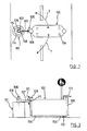
- Fig. 2 is a front view of the barrier of Fig. 1 .
- Fig. 3 is a top view of a barrier similar to that of Fig. 1 , further comprising a seat.
- Fig. 4 is a lateral view of a barrier similar to that of Fig. 1 , but comprising two moving elements connected to a single fixed element.
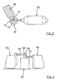
- Fig. 5 is a view of a motorized road barrier according to the invention, where thicker lines show the main internal mechanism.
- Fig. 6 and Fig. 7 are enlargements of some particulars of Fig. 5 .
- Fig 8a and Fig. 8b show the functioning of a position sensor for detecting the end of the stroke, that is provided in a preferred embodiment of the invention.
- Fig. 9 is a top view of the barrier of Fig. 5 in closed and open position, respectively with thick lines and thin lines.
- Fig. 10 is a perspective view of the barrier of Fig. 5 , where the cover of the base element is removed to show the motor and other internal components.
- the traffic barrier essentially comprise a base element 101 and a moving element 102, pivotally connected to the base element 101 by means of a hinge 103.
- Said hinge 103 allows the moving element 102 to swing along a substantially arc-shaped trajectory T.
- Both elements 101 and 102 are conveniently elements for urban decoration such as flower-holders, seats or others, made of wood or concrete.
- the moving element 102 comprise a ground rest, preferably obtained with pivoting wheels 104, and is connected to the fixed element 101 by means of a hinge 105 with a substantially horizontal axis, that allows the moving element 102 to tilt on a vertical plane, following the profile of the roadbed.
- the upper face of the base element 101 comprise a pin 106; the moving element 102 is connected to the base element 101 with an arm 107, having one end fitted with a collar 108 adapted to be freely inserted on said pin 106.
- the opposite end of the arm 107 is connected to the moving element 102 by said hinge 105.
- the moving element 102 comprise a support 109, for example a tubular made of stainless steel; two drilled plates 110 are fixed to said support 109, and the end of the arm 107 has a hole and is connected to said plates 110 by a pin 111, thus realizing the hinge 105.
- the moving element 102 may also comprise a plurality of supports 109, for easy connection to other elements for urban decoration, in a modular system.
- the moving element 102 is preferably fitted with stop means, realized for example with a further ground rest 112 that can be extracted with a screw drive, for avoiding undesired movement of the element 102, e.g. caused by its weight.
- the upper face of the base element 101 comprise a plate 114 with holes 115, that allows to connect other fixed element like a seat 116, by means of screws 117 or equivalent reversible connecting means.
- a plurality of moving elements 102 may be connected to the same base element 101, for regulating traffic on crossroads.
- the arms 107 of the various elements 102 are staggered as shown in fig. 4 .
- Fig. 5 to 10 is a motorized road barrier realized according to the invention, essentially comprising a moving element 201, which is main longitudinally extending, pivotally connected to a vertical axis 202 and provided with a mobile ground rest, realized by a wheel 203, connected to an electric motor 204.
- the motor 204 is housed in a base element 205, external to the moving element 201, and is supported by a frame structure 206 which is also rotating around the vertical axis 202.
- the moving element 201 is connected to said structure 206 by means of a hinge pin 207 having a substantially horizontal axis, thus realizing a hinge that allows the moving element to tilt on a vertical plane.
- the motor 204 is connected to the driving wheel 203 by a transmission shaft 208, that is provided with at least one articulated joint, advantageously a Cardan- or universal joint.
- the transmission shaft 208 is connected to the driving shaft of the motor 204 by a first universal joint 211, and is connected to the wheel 203 by a second universal joint 212.
- the transmission shaft is conveniently realized in two parts connected by a slip joint 213. A certain axial slip between the two parts of the shaft is therefore permitted to compensate for the variation of axial distance between motor 204 and wheel 203, that is caused by the inclination of the moving element 201 that can be induced by a roadbed with a considerable gradient.
- a reduction gear 210 is provided between the motor 204 and the transmission shaft 208, which in the preferred embodiment is an angular reduction gear, for allowing to install the motor 204 with vertical axis, thus reducing overall dimensions.
- the frame structure 206 is substantially realized with a casing that comprises vertical rods, reinforcing collars and a bottom platform, resting on a plate 214, this last being fixed with screws to a counter-plate 215 secured to the ground.
- the moving element 201 is connected to the pin 207 through a bracket 209, whose arms have one end fixed to said body and the opposite end engaging said pin.
- the bracket 209 is advantageously provided with a top cover, not shown, which is openable or removable. Said cover allows easy access to the universal joint 211, for disconnection of shaft 208 from reduction gear 210 and manual operation of the barrier in case of power failure.
- the universal joint 211 is conveniently of the kind with a locking ring, for quick coupling to the shaft.
- the top cover of the bracket 209 can be realized essentially with two metal sheets, positioned in contact one on the other, for leaving the element 201 free to tilt around the pin 207.
- the element 201 may be, for example, made of concrete, the wheel 203 being supported by a journal 218 fixed to a steel cross-member screwed to the bottom of the element 201 itself.
- mobile contacts with adjustable position activated by contact with a stationary element, are advantageously provided, to produce a signal that is correlated to the angular position of the moving element 201 on the horizontal plane, for example for automatic stop at the end of the stroke.
- said contacts may comprise a switch 220 fixed to a support 221, whose position is adjustable on a guide 222 associated to the frame structure 206.
- said switch 220 comprise a contact 223 and a flexible blade 224, adapted to cooperate with a stationary element 225, that is fixed, for example, to the plate 214.
- the barrier may also comprise some sensors, not shown, housed in the base 205 and rotating with the moving element 201, that detect obstacles on its trajectory and, if any, immediately stop the motor.
- the barrier is also equipped with a control panel 230, advantageously housed in the base 205.
- a key, badge or remote command system can be provided, as well as a temporized automatic command system for opening or closing at predetermined hours and for emergency and automatic stop.
- the moving element 201 is preferably a flower-holder, having the shape illustrated in the figures, substantially of a parallelepiped with rounded ends, that is nice-looking and easy to introduce even in historical centres.
- the moving element 201 may also be another element for street furniture, and may comprise light signals, road signs, information for tourists, and so on.
- the base element 205 is conveniently provided with a protective cover, and is shaped as a common cylindrical traffic barrier.
- the materials employed may be any according to requirements and to the state of the art.
Landscapes
- Engineering & Computer Science (AREA)
- Architecture (AREA)
- Civil Engineering (AREA)
- Structural Engineering (AREA)
- Refuge Islands, Traffic Blockers, Or Guard Fence (AREA)
- Road Signs Or Road Markings (AREA)
- Gyroscopes (AREA)
- Optical Communication System (AREA)
- Optical Modulation, Optical Deflection, Nonlinear Optics, Optical Demodulation, Optical Logic Elements (AREA)
- Traffic Control Systems (AREA)
Claims (14)
- Ortsveränderliche Verkehrsschranke bestehend aus einem beweglichen Element (102), (201), das um eine Hochachse schwingt und mindestens eine Bodenstütze (104), (203) umfasst, einem Grundelement (101), (205), an das genanntes bewegliches Element durch Einrichtungen (107), (209) verbunden ist, die ein Gelenk mit waagerechter Achse umfassen, sodass genanntes bewegliches Element an einer Hochachse schwenken kann, dadurch gekennzeichnet, dass genannte Bodenstütze mindestens ein Rad umfasst, das sich am Straßenbett während der Schwenkbewegung bewegt und das in Kooperation mit genanntem Gelenk mit waagerechter Achse ermöglicht, dass das bewegliche Element an einer senkrechten Ebene schwenkt, sodass das bewegliche Element dem Profil des Straßenbetts folgen kann.
- Verkehrsschranke nach Anspruch 1, dadurch gekennzeichnet, dass sich genanntes bewegliches Element (102), (201) hauptsächlich der Länge nach erstreckt, damit es in der Lage ist, zu einem Hindernis für die Fahrzeuge zu werden und dass genanntes Grundelement (101), (205) im wesentlichen zylindrisch oder polygonal ist.
- Verkehrsschranke nach Anspruch 1, dadurch gekennzeichnet, dass genannte Hochachse in der Mitte des genannten Grundelementes (101), (205) verläuft.
- Verkehrsschranke nach Anspruch 1, dadurch gekennzeichnet, dass sie einen abnehmbaren Hebel (113) für manuelle Eingriffe umfasst.
- Verkehrsschranke nach Anspruch 1, dadurch gekennzeichnet, dass sie Halteeinrichtungen (112) umfasst.
- Verkehrsschranke nach Anspruch 1, dadurch gekennzeichnet, dass genanntes Grundelement (101) Verbindungseinrichtungen (114) für weitere Elemente (116) zum Zwecke städtischer Dekoration oder anderer Nutzen umfasst.
- Verkehrsschranke nach Anspruch 1, dadurch gekennzeichnet, dass genanntes Grundelement (101) ortsgebunden ist und einen Stift (106) umfasst und dass die Einrichtungen zum Verbinden des beweglichen Elements (102) an das Grundelement (101) einen Arm (107) umfassen, der ein mit einem Bund (108) ausgerüstetes Ende hat, um auf genannten Stift (106) frei eingesetzt zu werden, während genannter Gelenkteil mit der waagerechten Achse (105) das andere Ende des Arms (107) an das bewegliche Element (102) verbindet.
- Verkehrsschranke nach Anspruch 1, in der die Bodenstütze (203) des beweglichen Elements (201) an Motoreinrichtungen (204) verbunden ist, dadurch gekennzeichnet, dass:- die Motoreinrichtungen (204) an genanntes Grundelement (205) verbunden und von einer Rahmenstruktur (206) getragen sind, die auch um genannte Hochachse rotiert;- die Bodenstütze (203) an genannte Motoreinrichtungen (204) durch eine mit mindestens einem Gelenk (211), (212) ausgerüstete Übertragungswelle (208) verbunden ist.
- Verkehrsschranke nach Anspruch 6, dadurch gekennzeichnet, dass das bewegliche Element (201) mit der Rahmenkonstruktion (206) durch eine Halterung (209) verbunden ist, bestehend aus Armen mit einem Ende, das am genannten Körper (1) befestigt ist und dem gegenüberliegenden Ende, das in einen Stift (207) eingreift, um genanntes Gelenk mit waagerechter Achse zu realisieren.
- Verkehrsschranke nach Anspruch 6, dadurch gekennzeichnet, dass die Übertragungswelle (208) mit einem ersten Kardangelenk (211) für die Verbindung an die Triebwelle des Motors (204) und einem zweiten Kardangelenk (212) für die Verbindung an die bewegliche Bodenstütze (203) ausgerüstet ist.
- Verkehrsschranke nach Anspruch 6, dadurch gekennzeichnet, dass die Übertragungswelle (208) aus mindestens zwei Teilen besteht, die durch ein axiales Schiebegelenk (213) miteinander verbunden sind.
- Verkehrsschranke nach Anspruch 6, dadurch gekennzeichnet, dass genannte Rahmenstruktur (206) auf einer Platte (214) aufliegt, die auf eine am Boden gesicherte Gegenplatte (215) befestigt werden kann.
- Verkehrsschranke nach Anspruch 6, dadurch gekennzeichnet, dass sie bewegliche Kontakte (224) umfasst, die mit dem beweglichen Element verbunden sind und mit standfesten Kontakten (225) zusammenwirken, um ein mit der Winkellage des genannten beweglichen Elements auf einer Horizontalebene korreliertes Signal zu geben.
- Verkehrsschranke nach Anspruch 6, dadurch gekennzeichnet, dass sie im Grundelement (205) untergebrachte Sensoren umfasst, die in der Lage sind, Hindernisse auf der Kurve des beweglichen Elements (201) zu ermitteln und den Motor (204) zu arretieren.
Applications Claiming Priority (4)
| Application Number | Priority Date | Filing Date | Title |
|---|---|---|---|
| IT000018A ITCR20020018A1 (it) | 2002-09-17 | 2002-09-17 | Barriera mobile per uso arredo urbano |
| ITCR20020018 | 2002-09-17 | ||
| ITCR20030007 ITCR20030007A1 (it) | 2003-05-28 | 2003-05-28 | Perfezionamento di barriera stradale mobile motorizzata. |
| ITCR20030007 | 2003-05-28 |
Publications (3)
| Publication Number | Publication Date |
|---|---|
| EP1400632A2 EP1400632A2 (de) | 2004-03-24 |
| EP1400632A3 EP1400632A3 (de) | 2004-10-27 |
| EP1400632B1 true EP1400632B1 (de) | 2010-04-21 |
Family
ID=31948109
Family Applications (1)
| Application Number | Title | Priority Date | Filing Date |
|---|---|---|---|
| EP03425476A Expired - Lifetime EP1400632B1 (de) | 2002-09-17 | 2003-07-16 | Bewegliche Strassenverkehrssperre |
Country Status (4)
| Country | Link |
|---|---|
| EP (1) | EP1400632B1 (de) |
| AT (1) | ATE465302T1 (de) |
| DE (1) | DE60332201D1 (de) |
| ES (1) | ES2343455T3 (de) |
Families Citing this family (2)
| Publication number | Priority date | Publication date | Assignee | Title |
|---|---|---|---|---|
| ES2327591B1 (es) * | 2007-04-16 | 2010-08-04 | Puertas Cubells, S.L. | Jardinera movil. |
| CN109989369A (zh) * | 2019-04-24 | 2019-07-09 | 浙江金华甬金高速公路有限公司 | 节能水平旋转栏杆机 |
Family Cites Families (5)
| Publication number | Priority date | Publication date | Assignee | Title |
|---|---|---|---|---|
| DE7406696U (de) * | 1974-05-30 | Koppers H Gmbh | Sicherheitsschranke | |
| US2309381A (en) * | 1940-03-02 | 1943-01-26 | Thomas E Brown | Gate |
| US3589066A (en) * | 1969-05-26 | 1971-06-29 | Faller & Cooper Inc | Barrier gate |
| US5035082A (en) * | 1985-07-02 | 1991-07-30 | Embassy Gates Associates, L.P. | Gate support and operating mechanism |
| US4658543A (en) | 1985-07-03 | 1987-04-21 | Carr Frederick J | Swinging lift gate |
-
2003
- 2003-07-16 ES ES03425476T patent/ES2343455T3/es not_active Expired - Lifetime
- 2003-07-16 EP EP03425476A patent/EP1400632B1/de not_active Expired - Lifetime
- 2003-07-16 AT AT03425476T patent/ATE465302T1/de not_active IP Right Cessation
- 2003-07-16 DE DE60332201T patent/DE60332201D1/de not_active Expired - Lifetime
Also Published As
| Publication number | Publication date |
|---|---|
| ES2343455T3 (es) | 2010-08-02 |
| EP1400632A2 (de) | 2004-03-24 |
| EP1400632A3 (de) | 2004-10-27 |
| ATE465302T1 (de) | 2010-05-15 |
| DE60332201D1 (de) | 2010-06-02 |
Similar Documents
| Publication | Publication Date | Title |
|---|---|---|
| JP2815717B2 (ja) | 交通用障壁 | |
| US4934097A (en) | Barrier post free of jamming points | |
| US5509753A (en) | Retractable speed bump | |
| US6299336B1 (en) | Low profile lift mounting arrangement for telescoping mast | |
| US6460292B1 (en) | Barrier gate arm assembly and methods for use thereof | |
| US5466088A (en) | Vehicle barrier having a pivotal vehicle barricade and a cooperating pivotal signal barrier | |
| EP2864546B1 (de) | Zusammenklappbare barrikadenvorrichtung | |
| US4354771A (en) | Motorized curb barrier traffic-way controller | |
| US5572837A (en) | Pneumatic telescoping mast | |
| US5248215A (en) | Road barricade | |
| US20220379851A1 (en) | Turntable rotation device for assisting with safe and controlled directional movement and pivoting of stationary motorcycles | |
| EP1400632B1 (de) | Bewegliche Strassenverkehrssperre | |
| US7561066B2 (en) | Railroad wayside signal system | |
| CN111691326B (zh) | 一种高度可调的市政道路限高杆 | |
| KR950000877B1 (ko) | 전륜구동자동차의 자체동력원과 일반운전방식을 이용한 방향전환장치 장착 자동차 | |
| US4637694A (en) | Auxiliary rear view mirror assembly and outboard mirror | |
| US6705798B2 (en) | Cold planer | |
| ES2346587T3 (es) | Procedimienmto de regulacion de la posicion de un quitanieves y conjunto quitanieves correspondiente. | |
| JPH0731490U (ja) | バスの乗降口用補助ステップ装置 | |
| KR20030052745A (ko) | 교량상판의 회전을 위한 회전수용받침장치 | |
| NZ230292A (en) | Two piece remotely controlled barrier with each piece connected together at their apexes by a hinge | |
| CN215629561U (zh) | 一种用于市政建设用安全防护装置 | |
| BE1032229B1 (nl) | Inrichting voor het openen of sluiten van een slagboom | |
| US20240001892A1 (en) | Optional center lift jacking system accessory for turntable rotation device for assisting with safe and controlled directional movement and pivoting of stationary motorcycles | |
| RU2198979C2 (ru) | Оборудование плужное |
Legal Events
| Date | Code | Title | Description |
|---|---|---|---|
| PUAI | Public reference made under article 153(3) epc to a published international application that has entered the european phase |
Free format text: ORIGINAL CODE: 0009012 |
|
| AK | Designated contracting states |
Kind code of ref document: A2 Designated state(s): AT BE BG CH CY CZ DE DK EE ES FI FR GB GR HU IE IT LI LU MC NL PT RO SE SI SK TR |
|
| AX | Request for extension of the european patent |
Extension state: AL LT LV MK |
|
| PUAL | Search report despatched |
Free format text: ORIGINAL CODE: 0009013 |
|
| AK | Designated contracting states |
Kind code of ref document: A3 Designated state(s): AT BE BG CH CY CZ DE DK EE ES FI FR GB GR HU IE IT LI LU MC NL PT RO SE SI SK TR |
|
| AX | Request for extension of the european patent |
Extension state: AL LT LV MK |
|
| 17P | Request for examination filed |
Effective date: 20050427 |
|
| AKX | Designation fees paid |
Designated state(s): AT BE BG CH CY CZ DE DK EE ES FI FR GB GR HU IE IT LI LU MC NL PT RO SE SI SK TR |
|
| R17P | Request for examination filed (corrected) |
Effective date: 20050426 |
|
| RBV | Designated contracting states (corrected) |
Designated state(s): AT BE BG CH CY CZ DE DK EE ES FI FR GB GR HU IE IT LI LU MC NL PT RO SE SI SK TR |
|
| 17Q | First examination report despatched |
Effective date: 20080110 |
|
| GRAP | Despatch of communication of intention to grant a patent |
Free format text: ORIGINAL CODE: EPIDOSNIGR1 |
|
| GRAS | Grant fee paid |
Free format text: ORIGINAL CODE: EPIDOSNIGR3 |
|
| GRAA | (expected) grant |
Free format text: ORIGINAL CODE: 0009210 |
|
| AK | Designated contracting states |
Kind code of ref document: B1 Designated state(s): AT BE BG CH CY CZ DE DK EE ES FI FR GB GR HU IE IT LI LU MC NL PT RO SE SI SK TR |
|
| REG | Reference to a national code |
Ref country code: GB Ref legal event code: FG4D |
|
| REG | Reference to a national code |
Ref country code: CH Ref legal event code: EP |
|
| REG | Reference to a national code |
Ref country code: IE Ref legal event code: FG4D |
|
| REF | Corresponds to: |
Ref document number: 60332201 Country of ref document: DE Date of ref document: 20100602 Kind code of ref document: P |
|
| REG | Reference to a national code |
Ref country code: CH Ref legal event code: NV Representative=s name: ROSENICH PAUL; GISLER CHRISTIAN PATENTBUERO PAUL R |
|
| REG | Reference to a national code |
Ref country code: ES Ref legal event code: FG2A Ref document number: 2343455 Country of ref document: ES Kind code of ref document: T3 |
|
| REG | Reference to a national code |
Ref country code: NL Ref legal event code: VDEP Effective date: 20100421 |
|
| PG25 | Lapsed in a contracting state [announced via postgrant information from national office to epo] |
Ref country code: NL Free format text: LAPSE BECAUSE OF FAILURE TO SUBMIT A TRANSLATION OF THE DESCRIPTION OR TO PAY THE FEE WITHIN THE PRESCRIBED TIME-LIMIT Effective date: 20100421 Ref country code: SE Free format text: LAPSE BECAUSE OF FAILURE TO SUBMIT A TRANSLATION OF THE DESCRIPTION OR TO PAY THE FEE WITHIN THE PRESCRIBED TIME-LIMIT Effective date: 20100421 |
|
| PG25 | Lapsed in a contracting state [announced via postgrant information from national office to epo] |
Ref country code: FI Free format text: LAPSE BECAUSE OF FAILURE TO SUBMIT A TRANSLATION OF THE DESCRIPTION OR TO PAY THE FEE WITHIN THE PRESCRIBED TIME-LIMIT Effective date: 20100421 Ref country code: SI Free format text: LAPSE BECAUSE OF FAILURE TO SUBMIT A TRANSLATION OF THE DESCRIPTION OR TO PAY THE FEE WITHIN THE PRESCRIBED TIME-LIMIT Effective date: 20100421 Ref country code: AT Free format text: LAPSE BECAUSE OF FAILURE TO SUBMIT A TRANSLATION OF THE DESCRIPTION OR TO PAY THE FEE WITHIN THE PRESCRIBED TIME-LIMIT Effective date: 20100421 |
|
| PG25 | Lapsed in a contracting state [announced via postgrant information from national office to epo] |
Ref country code: GR Free format text: LAPSE BECAUSE OF FAILURE TO SUBMIT A TRANSLATION OF THE DESCRIPTION OR TO PAY THE FEE WITHIN THE PRESCRIBED TIME-LIMIT Effective date: 20100722 Ref country code: CY Free format text: LAPSE BECAUSE OF FAILURE TO SUBMIT A TRANSLATION OF THE DESCRIPTION OR TO PAY THE FEE WITHIN THE PRESCRIBED TIME-LIMIT Effective date: 20100421 |
|
| PG25 | Lapsed in a contracting state [announced via postgrant information from national office to epo] |
Ref country code: EE Free format text: LAPSE BECAUSE OF FAILURE TO SUBMIT A TRANSLATION OF THE DESCRIPTION OR TO PAY THE FEE WITHIN THE PRESCRIBED TIME-LIMIT Effective date: 20100421 Ref country code: PT Free format text: LAPSE BECAUSE OF FAILURE TO SUBMIT A TRANSLATION OF THE DESCRIPTION OR TO PAY THE FEE WITHIN THE PRESCRIBED TIME-LIMIT Effective date: 20100823 Ref country code: DK Free format text: LAPSE BECAUSE OF FAILURE TO SUBMIT A TRANSLATION OF THE DESCRIPTION OR TO PAY THE FEE WITHIN THE PRESCRIBED TIME-LIMIT Effective date: 20100421 |
|
| PLBE | No opposition filed within time limit |
Free format text: ORIGINAL CODE: 0009261 |
|
| STAA | Information on the status of an ep patent application or granted ep patent |
Free format text: STATUS: NO OPPOSITION FILED WITHIN TIME LIMIT |
|
| PG25 | Lapsed in a contracting state [announced via postgrant information from national office to epo] |
Ref country code: SK Free format text: LAPSE BECAUSE OF FAILURE TO SUBMIT A TRANSLATION OF THE DESCRIPTION OR TO PAY THE FEE WITHIN THE PRESCRIBED TIME-LIMIT Effective date: 20100421 Ref country code: RO Free format text: LAPSE BECAUSE OF FAILURE TO SUBMIT A TRANSLATION OF THE DESCRIPTION OR TO PAY THE FEE WITHIN THE PRESCRIBED TIME-LIMIT Effective date: 20100421 Ref country code: MC Free format text: LAPSE BECAUSE OF NON-PAYMENT OF DUE FEES Effective date: 20100731 Ref country code: CZ Free format text: LAPSE BECAUSE OF FAILURE TO SUBMIT A TRANSLATION OF THE DESCRIPTION OR TO PAY THE FEE WITHIN THE PRESCRIBED TIME-LIMIT Effective date: 20100421 |
|
| GBPC | Gb: european patent ceased through non-payment of renewal fee |
Effective date: 20100721 |
|
| 26N | No opposition filed |
Effective date: 20110124 |
|
| PG25 | Lapsed in a contracting state [announced via postgrant information from national office to epo] |
Ref country code: IT Free format text: LAPSE BECAUSE OF NON-PAYMENT OF DUE FEES Effective date: 20100716 |
|
| PG25 | Lapsed in a contracting state [announced via postgrant information from national office to epo] |
Ref country code: IE Free format text: LAPSE BECAUSE OF NON-PAYMENT OF DUE FEES Effective date: 20100716 Ref country code: GB Free format text: LAPSE BECAUSE OF NON-PAYMENT OF DUE FEES Effective date: 20100721 |
|
| PG25 | Lapsed in a contracting state [announced via postgrant information from national office to epo] |
Ref country code: BG Free format text: LAPSE BECAUSE OF FAILURE TO SUBMIT A TRANSLATION OF THE DESCRIPTION OR TO PAY THE FEE WITHIN THE PRESCRIBED TIME-LIMIT Effective date: 20100421 Ref country code: LU Free format text: LAPSE BECAUSE OF NON-PAYMENT OF DUE FEES Effective date: 20100716 Ref country code: HU Free format text: LAPSE BECAUSE OF FAILURE TO SUBMIT A TRANSLATION OF THE DESCRIPTION OR TO PAY THE FEE WITHIN THE PRESCRIBED TIME-LIMIT Effective date: 20101022 |
|
| PG25 | Lapsed in a contracting state [announced via postgrant information from national office to epo] |
Ref country code: TR Free format text: LAPSE BECAUSE OF FAILURE TO SUBMIT A TRANSLATION OF THE DESCRIPTION OR TO PAY THE FEE WITHIN THE PRESCRIBED TIME-LIMIT Effective date: 20100421 |
|
| PG25 | Lapsed in a contracting state [announced via postgrant information from national office to epo] |
Ref country code: BG Free format text: LAPSE BECAUSE OF FAILURE TO SUBMIT A TRANSLATION OF THE DESCRIPTION OR TO PAY THE FEE WITHIN THE PRESCRIBED TIME-LIMIT Effective date: 20100721 |
|
| REG | Reference to a national code |
Ref country code: FR Ref legal event code: PLFP Year of fee payment: 14 |
|
| REG | Reference to a national code |
Ref country code: FR Ref legal event code: PLFP Year of fee payment: 15 |
|
| REG | Reference to a national code |
Ref country code: FR Ref legal event code: PLFP Year of fee payment: 16 |
|
| PGFP | Annual fee paid to national office [announced via postgrant information from national office to epo] |
Ref country code: DE Payment date: 20191029 Year of fee payment: 17 |
|
| PGFP | Annual fee paid to national office [announced via postgrant information from national office to epo] |
Ref country code: ES Payment date: 20191104 Year of fee payment: 17 Ref country code: BE Payment date: 20191028 Year of fee payment: 17 Ref country code: FR Payment date: 20191025 Year of fee payment: 17 |
|
| PGFP | Annual fee paid to national office [announced via postgrant information from national office to epo] |
Ref country code: CH Payment date: 20191029 Year of fee payment: 17 |
|
| REG | Reference to a national code |
Ref country code: CH Ref legal event code: PCAR Free format text: NEW ADDRESS: ROTENBODENSTRASSE 12, 9497 TRIESENBERG (LI) |
|
| REG | Reference to a national code |
Ref country code: DE Ref legal event code: R119 Ref document number: 60332201 Country of ref document: DE |
|
| REG | Reference to a national code |
Ref country code: DE Ref legal event code: R082 Ref document number: 60332201 Country of ref document: DE Representative=s name: KUHNEN & WACKER PATENT- UND RECHTSANWALTSBUERO, DE |
|
| REG | Reference to a national code |
Ref country code: CH Ref legal event code: PL |
|
| REG | Reference to a national code |
Ref country code: BE Ref legal event code: MM Effective date: 20200731 |
|
| PG25 | Lapsed in a contracting state [announced via postgrant information from national office to epo] |
Ref country code: FR Free format text: LAPSE BECAUSE OF NON-PAYMENT OF DUE FEES Effective date: 20200731 Ref country code: LI Free format text: LAPSE BECAUSE OF NON-PAYMENT OF DUE FEES Effective date: 20200731 Ref country code: CH Free format text: LAPSE BECAUSE OF NON-PAYMENT OF DUE FEES Effective date: 20200731 |
|
| PG25 | Lapsed in a contracting state [announced via postgrant information from national office to epo] |
Ref country code: DE Free format text: LAPSE BECAUSE OF NON-PAYMENT OF DUE FEES Effective date: 20210202 Ref country code: BE Free format text: LAPSE BECAUSE OF NON-PAYMENT OF DUE FEES Effective date: 20200731 |
|
| REG | Reference to a national code |
Ref country code: ES Ref legal event code: FD2A Effective date: 20211203 |
|
| PG25 | Lapsed in a contracting state [announced via postgrant information from national office to epo] |
Ref country code: ES Free format text: LAPSE BECAUSE OF NON-PAYMENT OF DUE FEES Effective date: 20200717 |