EP1400190A2 - Entraínement électromoteur pour meuble - Google Patents
Entraínement électromoteur pour meuble Download PDFInfo
- Publication number
- EP1400190A2 EP1400190A2 EP03019043A EP03019043A EP1400190A2 EP 1400190 A2 EP1400190 A2 EP 1400190A2 EP 03019043 A EP03019043 A EP 03019043A EP 03019043 A EP03019043 A EP 03019043A EP 1400190 A2 EP1400190 A2 EP 1400190A2
- Authority
- EP
- European Patent Office
- Prior art keywords
- spindle nut
- furniture drive
- drive according
- electromotive furniture
- spindle
- Prior art date
- Legal status (The legal status is an assumption and is not a legal conclusion. Google has not performed a legal analysis and makes no representation as to the accuracy of the status listed.)
- Granted
Links
Images


Classifications
-
- A—HUMAN NECESSITIES
- A47—FURNITURE; DOMESTIC ARTICLES OR APPLIANCES; COFFEE MILLS; SPICE MILLS; SUCTION CLEANERS IN GENERAL
- A47C—CHAIRS; SOFAS; BEDS
- A47C20/00—Head -, foot -, or like rests for beds, sofas or the like
- A47C20/04—Head -, foot -, or like rests for beds, sofas or the like with adjustable inclination
- A47C20/041—Head -, foot -, or like rests for beds, sofas or the like with adjustable inclination by electric motors
-
- F—MECHANICAL ENGINEERING; LIGHTING; HEATING; WEAPONS; BLASTING
- F16—ENGINEERING ELEMENTS AND UNITS; GENERAL MEASURES FOR PRODUCING AND MAINTAINING EFFECTIVE FUNCTIONING OF MACHINES OR INSTALLATIONS; THERMAL INSULATION IN GENERAL
- F16H—GEARING
- F16H25/00—Gearings comprising primarily only cams, cam-followers and screw-and-nut mechanisms
- F16H25/18—Gearings comprising primarily only cams, cam-followers and screw-and-nut mechanisms for conveying or interconverting oscillating or reciprocating motions
- F16H25/20—Screw mechanisms
- F16H25/24—Elements essential to such mechanisms, e.g. screws, nuts
- F16H25/2472—Safety nuts
Definitions
- the invention relates to an electromotive furniture drive with a spindle and a spindle nut placed on it.
- the electromotive furniture drive in question is available in many versions known. It can be equipped with a drive motor and a spindle, However, it can also be equipped with several spindles assigned by Drive motors or driven by a common drive motor. Such drives are referred to as single or double drives. Furthermore are also known designs in which the output member of the speed of the Drive motor lowering gear is driven and the spindle is fixed. The entire drive is then on when the drive motor is switched on Move the spindle.
- the furniture drives in question are mass-produced items view and should be as inexpensive to manufacture. To be favoured they are used as drives for couch elements and armchairs.
- the spindle is made of steel and the Spindle nut made from a plastic. Because of the properties of this The wear of the threads of the spindle nut is higher than that of the materials the spindle. In addition, the resilience is made of a plastic Component not as high as that of a steel one. Accordingly, must In the case of furniture drives, the spindle nut is considered a wearing part.
- this Safety spindle nut consists of a safety nut and a working nut. These two nuts can be fixed together, they can also be connected to one another via connecting elements, for example pins be connected, which shear when a certain torque is exceeded.
- Such solutions are unsatisfactory because the safety nut Function of the spindle nut takes over if this one due to wear Has reached a state in which the function is no longer guaranteed.
- the Furniture drive can then continue to be operated until the safety nut is no longer functional or breaks. This results in, that the operating time is only extended, but not in time for the user it is signaled that an exchange of the spindle nut is necessary. The As a result, suggestions made so far are not a solution to the problem.
- the invention has for its object an electromotive furniture drive of the type described in more detail at the beginning so that the user perceives can, if the threads of the spindle nut up to a certain Degrees are worn out so that it can be decided that the spindle nut is replaced or if the spindle nut breaks, if necessary that the connected component can still be lowered, but not on any If the operation of the furniture drive is enabled.
- the spindle nut has safety threads and motion threads and that the play of the safety threads against the threads the spindle is larger than that of the movement threads to the threads the spindle.
- the spindle nut can also be used as a safety spindle nut are called, since one can assume that normally no Breakage is possible, as will be explained.
- the safety threads of the spindle nut a braking or blocking device when in contact with the threads of the spindle form. If they form a braking device, they could be designed so that the component connected to the furniture drive is still lowered can, however, that lifting due to the higher force is not is more possible. If they are designed as a blocking device, one would be a method not possible anymore. In both cases the shutdown could be caused by the Overcurrent detection with which the furniture drive is normally equipped is.
- the braking or blocking effect could be designed accordingly
- the safety threads are made by, for example, the threads defining values can be changed.
- the safety threads consist of a material which has a higher strength compared to the movement threads.
- the motion threads are made of a plastic
- the safety threads could be made of a reinforced plastic, preferably a glass fiber reinforced plastic.
- the safety threads are made of the same material as the threads the spindle, usually the spindle is made of steel. It is coming then to the unusual combination of materials that would lead to squeaking, so that can be interpreted as a signal for a change of the spindle nut.
- the operation of the furniture drive would make this unusual Material combination lead to stiffness, so that overcurrent detection would be reactivated.
- the safety threads are part of a thread insert, which is in a driving connection with the spindle nut.
- the arrangement of the Threaded insert can be made in different ways, for example in which it inserted into a correspondingly designed recess of the spindle nut, preferably is positively inserted.
- This version is advantageous if the Furniture drive from the start with the safety threads Spindle nut is equipped.
- the thread insert is flanged to the spindle nut in a functional manner. This execution would for retrofitting furniture drives that are already in operation to offer.
- the threaded insert is expediently designed as a truncated cone in such a way that that when the safety threads come into contact with the threads the spindle has a perceptible noise, braking or blocking the spindle takes place. If the spindle is braked or blocked, overcurrent detection would be activated again.
- the frustoconical Thread insert could be designed and so be in contact with the spindle nut, that when the safety threads contact the threads of the Spindle the thread insert moves a little, so that from the outside Act forces that lead to a deformation, so that the braking or Blocking occurs.
- the thread insert has at least one longitudinal slot is provided, which engages over a web of the spindle nut. This is done a positive connection between the spindle nut and the threaded insert so that there is a non-rotatable connection. Also relieved the longitudinal slot the deformation of the thread insert for the purpose of bringing about the blockage or braking. So that the thread insert can deform, it is advantageous if, in addition to the longitudinal slot, one or more Slots are provided in the threaded insert. These slots extend but not over the entire length, but they are in a preferred embodiment longer than half the length of the thread insert.
- the thread insert is designed as a double truncated cone, so that the outer surface by two in opposite directions inclined conical surfaces is formed.
- the thread insert deformed when displaced in both directions, so that a Braking or blocking both when lifting and lowering the connected component.
- This thread insert could also be used with a Longitudinal slot be equipped.
- the threaded insert equipped spindle nut is formed from two half shells.
- the half-shells are useful connected by a film hinge so that the parts are not accidentally get lost. So there is no misalignment in the area of the parting line the thread flanks of the two half shells, it is advisable if centering pins on one half-shell and on the other half-shell are in the correct position corresponding center holes are provided. This will cause a shift a half shell in the longitudinal direction of the spindle avoided.
- the half shells could either be positively guided in a guide channel of the furniture drive or they could be connected to one another via connecting elements.
- the spindle nut is advantageously designed in the form of an annular cross section. To secure it against twisting, it is then on the outer surface with several Longitudinally extending guide webs equipped in guide grooves of the flange tube.
- the thread insert attached to an end face of the spindle nut preferably with a positive fit the spindle nut is connected.
- This version is for retrofitting furniture drives in operation. So that a sufficiently firm Connection is achieved, it is provided that the threaded insert in a sleeve is used, which is positively connected to the spindle.
- This sleeve points expediently segments on the end face facing the spindle nut which engage in correspondingly designed recesses in the spindle nut.
- the positive connection can also be designed as a snap-in connection. This expediently takes place in that the sleeve has spring tongues, the free ends formed as locking lugs, which are in a groove or in undercuts intervention.
- the thread insert as Double cone is formed.
- the thread insert at a distance from an end area of a two-part spindle nut is arranged. Since the thread insert in turn is at least a conical one Has the outer surface, the spindle nut is in the place of the threaded insert either equipped with a corresponding conical counter surface or it a corresponding inner cone sleeve is inserted into the spindle nut. Further Embodiments are conceivable. It is essential that the plastic manufactured spindle nut does not break. However, this break occurs only after the previous one Deformation or after a corresponding wear of the threads.
- a contact element is inserted into the spindle nut, based on the original condition of the spindle nut of an area of the Thread is standing.
- a contact element is inserted in at least one Thread of the threaded insert. This could also extend to a flank of the thread.
- the spindle contacted could either be displayed to the user be, for example by lighting up a light source or by an acoustic Signal that the spindle nut needs to be replaced.
- the drive is stopped.
- each spindle nut 10 is with one coupled to adjustable furniture component.
- the respective connection sets up depends on the type of drive and the design of the furniture component to be adjusted.
- the internal thread of each spindle nut is 10 a trapezoidal thread, so that the threaded spindles, not shown Trapezoidal screws are.
- the Threads can also be designed as pointed threads.
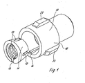
- each spindle nut 10 is equipped with a threaded insert, which is in a fixed connection with the spindle nut 10, i.e.
- the threaded insert 11 is designed as a truncated cone. It is in a corresponding conical shape of the spindle nut 10 used, as shown in Figure 3.
- the internal threads of the thread insert 11 are safety threads, while the threads of the spindle nut There are 10 movement threads, i.e.
- the threads of the thread insert 11 are designed so that they have a larger play on the threads of the spindle, not shown, have as the movement threads of the spindle nut 10.
- the safety threads of the thread insert come 11 in the normal operating state of the spindle nut 10 not in contact with the Threads of the spindle.
- the game between the Movement threads of the spindle nut 10 and the threads of the Spindle to the size of the game between the safety threads and the Threads of the spindle have grown, the safety threads come in contact with the threads of the spindle.
- the threaded insert 11 could consist of a material that has a higher strength than the material, from which the spindle nut 10 is made.
- the Spindle nut 10 made of a plastic, preferably POM, during the Thread insert 11 also made of a plastic, preferably a glass fiber reinforced Plastic, made of metal, for example a sintered metal, a non-ferrous metal or is also made of steel.
- a combination of materials should be aimed for that signals to the user that the safety threads Have come into contact with the threads of the spindle. For example indicated by noises. Will the motion threads However, the spindle nut 10 is worn even further, an increased driving torque required, which for switching off the drive, for example through overcurrent detection.
- the movement threads of the spindle nut 10 continue to wear out despite the contact of the safety threads, because the number of movement threads is significantly larger than the number of Security threads.
- the thread insert 11 with three slots arranged at the same angular distance from one another 12 provided that extend in the longitudinal direction, but not over the entire Length of the threaded insert 11. Because the outer surface of the threaded insert 11 is conical , the threaded insert 11 can be a little bit smaller than the spindle move so that it is compressed, albeit slightly. This will the friction between the safety threads and the threads of the Spindle increases, so that an increased power requirement is necessary, which can be used can to switch the furniture drive.
- the threaded insert is 11 still provided with a continuous longitudinal slot 13 through which the connection is created with the spindle nut 10, because in this longitudinal slot 13 Inner web 14 of the spindle nut 10 engages.
- the longitudinal slot 13 is at the top.
- the threaded insert 11 is also the conical receptacle designed according to the threaded insert 11 15 recognizable.
- FIG. 3 shows that the threaded insert 11 corresponds in analogy to the spindle nut 10 is inserted.
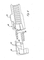
- Figure 4 shows a further embodiment.
- the main difference from that Execution according to Figures 1 to 3 consists in the differently designed thread insert 16, in this embodiment as a two-part truncated cone Is provided.
- the conical outer surfaces are inclined in opposite directions. Otherwise meet the explanations regarding the safety threads and the materials to, which are described in the threaded insert 11.
- This version offers the advantage that the thread insert 17a, 17b acts in both directions of force along the spindle nut 10 is obtained.
- One solution, one as a truncated cone insert the threaded insert into the spindle nut, show the figures 4 to 6.
- the threaded insert consists of the two threaded insert halves 17a and 17b.
- the spindle nut halves 17a and 17b are through Film hinges 18, 19 connected to each other. After inserting the threaded insert halves 17a, 17b in the corresponding receptacles are the two spindle nut halves 17a, 17b folded. So that they are not against each other move in the longitudinal direction, is the spindle nut half in the illustrated embodiment 17b provided with four protruding centering pins 20 which are brought together in the State of the two spindle nut halves 10a, 10b in corresponding Engage holes 21 of the spindle nut half 10 centering.
- the spindle nut 10 can in a correspondingly designed guide channel of the electromotive Furniture drive to be guided. However, you can also use suitable ones Connecting elements, preferably by positive and / or non-positive acting fasteners are held together.
- FIG. 4 also shows that a push tube or a lifting tube is placed on the spindle nut 10 22 is set.
- Figures 1 to 6 also show that the outer surface of each Threaded nut 10 with a plurality of longitudinally extending guide webs 23 is equipped, the corresponding grooves of the flange tube or one other adjacent component are guided so that the spindle nut 10 against Rotation is secured.
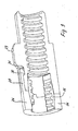
- a similar thread insert is again used 11 used, but which is fixed to an end face of the spindle nut 10 is.
- it is inserted into an inner cone sleeve 24.
- This is on the spindle nut 10 facing side equipped with projecting segments 25, 26, which engage in corresponding recesses 27, 28 of the spindle nut 10.
- This version is special Suitable for retrofitting furniture drives.
- two threaded inserts 16 are used, which as Double cones are designed. As FIG. 9 shows, the threaded insert 16 lies partially in the inner cone sleeve 24 and partially in the spindle nut 10.
- the apex of the two conical surfaces lies exactly in the parting plane between the Inner cone sleeve 24 and the spindle nut 10.
- the inner cone sleeve 24 is with the spindle nut 10 locked. To do this, it is spaced from one another by several standing spring tongues 29 equipped, the free ends of which are designed as locking lugs 30 are in the assembled state according to Figure 9 either in a Undercut or engage in a circumferential groove 31.
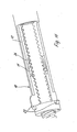
- Execution 10 is again equipped with a threaded insert 11, which as Truncated cone is designed. When merged, it is in one Inner cone sleeve 24. This is through a securing cage 32 with the spindle nut 10 connected.
- the thread insert 11 there is the thread insert 11 at a distance from the ends of the spindle nut 10.
- the truncated cone trained threaded insert 11 is supported with its conical surface on a Inner cone surface. This inner cone can be inserted into the spindle nut 10 or form an integral molded part with the spindle nut 10.
- Independent of the design and position of the threaded insert 11 and 16 are all designs equipped with the guide webs 23.
- the threaded insert 11 can be designed in many ways, but one is preferred annular training. This ring can be closed in a circular symmetry, he can be separated or formed as a ring section or as a segment. Furthermore, the threaded insert can be formed in one or more parts.
- the invention is not restricted to the exemplary embodiments shown.
- Essential is that the spindle nut 10 is equipped with non-load-bearing threads is what is derived when this contact with the threads of the Get spindle. This can be caused, for example, by noise or when there is a Stiffness occurs due to overcurrent detection to stop the Lead furniture drive.
Landscapes
- Engineering & Computer Science (AREA)
- General Engineering & Computer Science (AREA)
- Mechanical Engineering (AREA)
- Health & Medical Sciences (AREA)
- General Health & Medical Sciences (AREA)
- Nursing (AREA)
- Furniture Connections (AREA)
- Types And Forms Of Lifts (AREA)
- Control Of Electric Motors In General (AREA)
- Power-Operated Mechanisms For Wings (AREA)
- Elimination Of Static Electricity (AREA)
- Transmission Devices (AREA)
Applications Claiming Priority (2)
| Application Number | Priority Date | Filing Date | Title |
|---|---|---|---|
| DE20214565U DE20214565U1 (de) | 2002-09-20 | 2002-09-20 | Elektromotorischer Möbelantrieb |
| DE20214565U | 2002-09-20 |
Publications (3)
| Publication Number | Publication Date |
|---|---|
| EP1400190A2 true EP1400190A2 (fr) | 2004-03-24 |
| EP1400190A3 EP1400190A3 (fr) | 2004-08-04 |
| EP1400190B1 EP1400190B1 (fr) | 2008-09-03 |
Family
ID=31896431
Family Applications (1)
| Application Number | Title | Priority Date | Filing Date |
|---|---|---|---|
| EP03019043A Expired - Lifetime EP1400190B1 (fr) | 2002-09-20 | 2003-08-22 | Entraînement électromoteur pour meuble |
Country Status (4)
| Country | Link |
|---|---|
| EP (1) | EP1400190B1 (fr) |
| AT (1) | ATE406821T1 (fr) |
| DE (2) | DE20214565U1 (fr) |
| DK (1) | DK1400190T3 (fr) |
Cited By (2)
| Publication number | Priority date | Publication date | Assignee | Title |
|---|---|---|---|---|
| EP2594156B1 (fr) | 2011-11-16 | 2015-02-25 | Paul Hettich GmbH & Co. KG | Colonne élévatrice télescopique d'une partie de meuble |
| US10058910B2 (en) | 2014-11-27 | 2018-08-28 | Tkr Spezialwerkzeuge Gmbh | Riveting tool |
Families Citing this family (3)
| Publication number | Priority date | Publication date | Assignee | Title |
|---|---|---|---|---|
| DE102005017429A1 (de) * | 2005-04-15 | 2006-10-19 | Bosch Rexroth Mechatronics Gmbh | Gewindetrieb mit überwachter Sicherheitsmutter |
| DE102008062391A1 (de) * | 2008-12-17 | 2010-06-24 | BROSE SCHLIEßSYSTEME GMBH & CO. KG | Spindelantrieb für ein Verstellelement eines Kraftfahrzeugs |
| DE202011103745U1 (de) | 2010-07-27 | 2012-01-17 | Linak A/S | Linearantrieb |
Citations (3)
| Publication number | Priority date | Publication date | Assignee | Title |
|---|---|---|---|---|
| EP0311478A1 (fr) * | 1987-10-08 | 1989-04-12 | Rockwell Automotive Body Systems-France En Abrege:Rockwell Abs-France | Vérin à vis à sécurité de surcharge pour élément déplaçable, tel qu'un siège |
| WO1996020361A1 (fr) * | 1994-12-23 | 1996-07-04 | Linak A/S | Actuateur lineaire et procede de fabrication |
| EP0995714A1 (fr) * | 1998-10-23 | 2000-04-26 | Alltec GmbH | Dispositif de sécurité pour un mécanisme de taraud linéaire |
Family Cites Families (4)
| Publication number | Priority date | Publication date | Assignee | Title |
|---|---|---|---|---|
| SE461088B (sv) * | 1988-12-21 | 1990-01-08 | Alimak Ab | Anordning vid skruvhiss |
| DK171217B1 (da) * | 1992-09-01 | 1996-07-29 | Linak As | Lineær aktuator |
| DE4333335A1 (de) * | 1993-09-29 | 1995-03-30 | Bayerische Park Und Lagersyste | Unter Last stehende Tragmutter |
| DE29823115U1 (de) * | 1998-12-28 | 1999-03-25 | OKIN Gesellschaft für Antriebstechnik mbH & Co. KG, 51645 Gummersbach | Linearantrieb |
-
2002
- 2002-09-20 DE DE20214565U patent/DE20214565U1/de not_active Expired - Lifetime
-
2003
- 2003-08-22 AT AT03019043T patent/ATE406821T1/de not_active IP Right Cessation
- 2003-08-22 EP EP03019043A patent/EP1400190B1/fr not_active Expired - Lifetime
- 2003-08-22 DE DE50310430T patent/DE50310430D1/de not_active Expired - Lifetime
- 2003-08-22 DK DK03019043T patent/DK1400190T3/da active
Patent Citations (3)
| Publication number | Priority date | Publication date | Assignee | Title |
|---|---|---|---|---|
| EP0311478A1 (fr) * | 1987-10-08 | 1989-04-12 | Rockwell Automotive Body Systems-France En Abrege:Rockwell Abs-France | Vérin à vis à sécurité de surcharge pour élément déplaçable, tel qu'un siège |
| WO1996020361A1 (fr) * | 1994-12-23 | 1996-07-04 | Linak A/S | Actuateur lineaire et procede de fabrication |
| EP0995714A1 (fr) * | 1998-10-23 | 2000-04-26 | Alltec GmbH | Dispositif de sécurité pour un mécanisme de taraud linéaire |
Cited By (3)
| Publication number | Priority date | Publication date | Assignee | Title |
|---|---|---|---|---|
| EP2594156B1 (fr) | 2011-11-16 | 2015-02-25 | Paul Hettich GmbH & Co. KG | Colonne élévatrice télescopique d'une partie de meuble |
| US10058910B2 (en) | 2014-11-27 | 2018-08-28 | Tkr Spezialwerkzeuge Gmbh | Riveting tool |
| EP3025807B1 (fr) * | 2014-11-27 | 2019-07-03 | TKR Spezialwerkzeuge GmbH | Outil de rivetage |
Also Published As
| Publication number | Publication date |
|---|---|
| EP1400190A3 (fr) | 2004-08-04 |
| EP1400190B1 (fr) | 2008-09-03 |
| DK1400190T3 (da) | 2009-01-05 |
| DE20214565U1 (de) | 2004-03-04 |
| DE50310430D1 (de) | 2008-10-16 |
| ATE406821T1 (de) | 2008-09-15 |
Similar Documents
| Publication | Publication Date | Title |
|---|---|---|
| EP1659298B1 (fr) | Entraînement linéaire | |
| DE102005020184B4 (de) | Linearantrieb | |
| DE2831201A1 (de) | Vorrichtung zum verstellen zweier beweglicher teile zueinander unter ausgleich des zwischen den teilen bestehenden spiels | |
| DE202005002585U1 (de) | Elektromotorischer Linearantrieb | |
| DE102012013979A1 (de) | Linaearaktuator und Verfahren zum Herstellen eines Linearaktuators | |
| EP1881236B1 (fr) | Entraînement par vis à billes | |
| DE2913885A1 (de) | Lamellenjalousie mit senkrecht angeordneten lamellen | |
| EP0591574A1 (fr) | Outil à main électrique motorisé | |
| DE19811917B4 (de) | Andruckvorrichtung für eine Zahnstange und deren Antriebsritzel | |
| DE10157020A1 (de) | Riemenscheibeneinheit | |
| DE102019118338A1 (de) | Drehmoment-Antriebskopf | |
| EP1400190A2 (fr) | Entraínement électromoteur pour meuble | |
| DE4219844A1 (de) | In axialer Richtung zusammendrückbarer Wickelträger | |
| DE10326660A1 (de) | Bolzen-Scheiben-Anordnung und deren Elemente | |
| DE102018120998B4 (de) | Trennungsmechanismus für Nabe und Elektromotorausgangswelle | |
| DE69102559T2 (de) | Scharnier mit integriertem Feststeller für Fahrzeugtüre oder andere Flügel. | |
| EP1102909B1 (fr) | Mecanisme de couplage destine a relier un dispositif d'immobilisation de porte a une charniere de porte de vehicule | |
| DE102011111853A1 (de) | Verstellbeschlag mit einem Axialsperrsystem zur Ablaufsicherung | |
| DE19960932B4 (de) | Linearantrieb | |
| EP2150716B1 (fr) | Embrayage | |
| DE20214566U1 (de) | Elektromotorischer Linearantrieb | |
| DE102014103558B3 (de) | Selbstschließendes Rollentürband | |
| DE102019115868B4 (de) | Spindelantrieb | |
| EP0900952A2 (fr) | Transmission à courroie | |
| DE202004009839U1 (de) | Verstellantrieb |
Legal Events
| Date | Code | Title | Description |
|---|---|---|---|
| PUAI | Public reference made under article 153(3) epc to a published international application that has entered the european phase |
Free format text: ORIGINAL CODE: 0009012 |
|
| AK | Designated contracting states |
Kind code of ref document: A2 Designated state(s): AT BE BG CH CY CZ DE DK EE ES FI FR GB GR HU IE IT LI LU MC NL PT RO SE SI SK TR |
|
| AX | Request for extension of the european patent |
Extension state: AL LT LV MK |
|
| PUAL | Search report despatched |
Free format text: ORIGINAL CODE: 0009013 |
|
| AK | Designated contracting states |
Kind code of ref document: A3 Designated state(s): AT BE BG CH CY CZ DE DK EE ES FI FR GB GR HU IE IT LI LU MC NL PT RO SE SI SK TR |
|
| AX | Request for extension of the european patent |
Extension state: AL LT LV MK |
|
| 17P | Request for examination filed |
Effective date: 20040917 |
|
| AKX | Designation fees paid |
Designated state(s): AT BE BG CH CY CZ DE DK EE ES FI FR GB GR HU IE IT LI LU MC NL PT RO SE SI SK TR |
|
| 17Q | First examination report despatched |
Effective date: 20061019 |
|
| GRAP | Despatch of communication of intention to grant a patent |
Free format text: ORIGINAL CODE: EPIDOSNIGR1 |
|
| GRAS | Grant fee paid |
Free format text: ORIGINAL CODE: EPIDOSNIGR3 |
|
| GRAA | (expected) grant |
Free format text: ORIGINAL CODE: 0009210 |
|
| AK | Designated contracting states |
Kind code of ref document: B1 Designated state(s): AT BE BG CH CY CZ DE DK EE ES FI FR GB GR HU IE IT LI LU MC NL PT RO SE SI SK TR |
|
| REG | Reference to a national code |
Ref country code: GB Ref legal event code: FG4D Free format text: NOT ENGLISH |
|
| REG | Reference to a national code |
Ref country code: CH Ref legal event code: EP |
|
| REG | Reference to a national code |
Ref country code: IE Ref legal event code: FG4D Free format text: LANGUAGE OF EP DOCUMENT: GERMAN |
|
| REF | Corresponds to: |
Ref document number: 50310430 Country of ref document: DE Date of ref document: 20081016 Kind code of ref document: P |
|
| REG | Reference to a national code |
Ref country code: DK Ref legal event code: T3 |
|
| PG25 | Lapsed in a contracting state [announced via postgrant information from national office to epo] |
Ref country code: NL Free format text: LAPSE BECAUSE OF FAILURE TO SUBMIT A TRANSLATION OF THE DESCRIPTION OR TO PAY THE FEE WITHIN THE PRESCRIBED TIME-LIMIT Effective date: 20080903 Ref country code: ES Free format text: LAPSE BECAUSE OF FAILURE TO SUBMIT A TRANSLATION OF THE DESCRIPTION OR TO PAY THE FEE WITHIN THE PRESCRIBED TIME-LIMIT Effective date: 20081214 |
|
| REG | Reference to a national code |
Ref country code: GB Ref legal event code: 732E Free format text: REGISTERED BETWEEN 20090129 AND 20090204 |
|
| PG25 | Lapsed in a contracting state [announced via postgrant information from national office to epo] |
Ref country code: SI Free format text: LAPSE BECAUSE OF FAILURE TO SUBMIT A TRANSLATION OF THE DESCRIPTION OR TO PAY THE FEE WITHIN THE PRESCRIBED TIME-LIMIT Effective date: 20080903 Ref country code: FI Free format text: LAPSE BECAUSE OF FAILURE TO SUBMIT A TRANSLATION OF THE DESCRIPTION OR TO PAY THE FEE WITHIN THE PRESCRIBED TIME-LIMIT Effective date: 20080903 |
|
| NLV1 | Nl: lapsed or annulled due to failure to fulfill the requirements of art. 29p and 29m of the patents act | ||
| REG | Reference to a national code |
Ref country code: IE Ref legal event code: FD4D |
|
| PG25 | Lapsed in a contracting state [announced via postgrant information from national office to epo] |
Ref country code: IE Free format text: LAPSE BECAUSE OF FAILURE TO SUBMIT A TRANSLATION OF THE DESCRIPTION OR TO PAY THE FEE WITHIN THE PRESCRIBED TIME-LIMIT Effective date: 20080903 Ref country code: BG Free format text: LAPSE BECAUSE OF FAILURE TO SUBMIT A TRANSLATION OF THE DESCRIPTION OR TO PAY THE FEE WITHIN THE PRESCRIBED TIME-LIMIT Effective date: 20081203 |
|
| PG25 | Lapsed in a contracting state [announced via postgrant information from national office to epo] |
Ref country code: SK Free format text: LAPSE BECAUSE OF FAILURE TO SUBMIT A TRANSLATION OF THE DESCRIPTION OR TO PAY THE FEE WITHIN THE PRESCRIBED TIME-LIMIT Effective date: 20080903 Ref country code: CZ Free format text: LAPSE BECAUSE OF FAILURE TO SUBMIT A TRANSLATION OF THE DESCRIPTION OR TO PAY THE FEE WITHIN THE PRESCRIBED TIME-LIMIT Effective date: 20080903 Ref country code: PT Free format text: LAPSE BECAUSE OF FAILURE TO SUBMIT A TRANSLATION OF THE DESCRIPTION OR TO PAY THE FEE WITHIN THE PRESCRIBED TIME-LIMIT Effective date: 20090203 Ref country code: RO Free format text: LAPSE BECAUSE OF FAILURE TO SUBMIT A TRANSLATION OF THE DESCRIPTION OR TO PAY THE FEE WITHIN THE PRESCRIBED TIME-LIMIT Effective date: 20080903 |
|
| PLBE | No opposition filed within time limit |
Free format text: ORIGINAL CODE: 0009261 |
|
| STAA | Information on the status of an ep patent application or granted ep patent |
Free format text: STATUS: NO OPPOSITION FILED WITHIN TIME LIMIT |
|
| PG25 | Lapsed in a contracting state [announced via postgrant information from national office to epo] |
Ref country code: EE Free format text: LAPSE BECAUSE OF FAILURE TO SUBMIT A TRANSLATION OF THE DESCRIPTION OR TO PAY THE FEE WITHIN THE PRESCRIBED TIME-LIMIT Effective date: 20080903 |
|
| 26N | No opposition filed |
Effective date: 20090604 |
|
| PG25 | Lapsed in a contracting state [announced via postgrant information from national office to epo] |
Ref country code: IT Free format text: LAPSE BECAUSE OF FAILURE TO SUBMIT A TRANSLATION OF THE DESCRIPTION OR TO PAY THE FEE WITHIN THE PRESCRIBED TIME-LIMIT Effective date: 20080903 |
|
| REG | Reference to a national code |
Ref country code: FR Ref legal event code: TP Ref country code: FR Ref legal event code: CD |
|
| PGFP | Annual fee paid to national office [announced via postgrant information from national office to epo] |
Ref country code: DK Payment date: 20090821 Year of fee payment: 7 Ref country code: FR Payment date: 20090819 Year of fee payment: 7 |
|
| PGFP | Annual fee paid to national office [announced via postgrant information from national office to epo] |
Ref country code: GB Payment date: 20090821 Year of fee payment: 7 |
|
| PG25 | Lapsed in a contracting state [announced via postgrant information from national office to epo] |
Ref country code: SE Free format text: LAPSE BECAUSE OF FAILURE TO SUBMIT A TRANSLATION OF THE DESCRIPTION OR TO PAY THE FEE WITHIN THE PRESCRIBED TIME-LIMIT Effective date: 20081203 |
|
| BERE | Be: lapsed |
Owner name: DEWERT ANTRIEBS- UND SYSTEMTECHNIK G.M.B.H. & CO. Effective date: 20090831 |
|
| PG25 | Lapsed in a contracting state [announced via postgrant information from national office to epo] |
Ref country code: MC Free format text: LAPSE BECAUSE OF NON-PAYMENT OF DUE FEES Effective date: 20090831 |
|
| REG | Reference to a national code |
Ref country code: CH Ref legal event code: PL |
|
| PG25 | Lapsed in a contracting state [announced via postgrant information from national office to epo] |
Ref country code: LI Free format text: LAPSE BECAUSE OF NON-PAYMENT OF DUE FEES Effective date: 20090831 Ref country code: CH Free format text: LAPSE BECAUSE OF NON-PAYMENT OF DUE FEES Effective date: 20090831 |
|
| PG25 | Lapsed in a contracting state [announced via postgrant information from national office to epo] |
Ref country code: BE Free format text: LAPSE BECAUSE OF NON-PAYMENT OF DUE FEES Effective date: 20090831 |
|
| PG25 | Lapsed in a contracting state [announced via postgrant information from national office to epo] |
Ref country code: GR Free format text: LAPSE BECAUSE OF FAILURE TO SUBMIT A TRANSLATION OF THE DESCRIPTION OR TO PAY THE FEE WITHIN THE PRESCRIBED TIME-LIMIT Effective date: 20081204 |
|
| PG25 | Lapsed in a contracting state [announced via postgrant information from national office to epo] |
Ref country code: AT Free format text: LAPSE BECAUSE OF NON-PAYMENT OF DUE FEES Effective date: 20090822 |
|
| REG | Reference to a national code |
Ref country code: DK Ref legal event code: EBP |
|
| GBPC | Gb: european patent ceased through non-payment of renewal fee |
Effective date: 20100822 |
|
| PG25 | Lapsed in a contracting state [announced via postgrant information from national office to epo] |
Ref country code: LU Free format text: LAPSE BECAUSE OF NON-PAYMENT OF DUE FEES Effective date: 20090822 |
|
| REG | Reference to a national code |
Ref country code: FR Ref legal event code: ST Effective date: 20110502 |
|
| PG25 | Lapsed in a contracting state [announced via postgrant information from national office to epo] |
Ref country code: HU Free format text: LAPSE BECAUSE OF FAILURE TO SUBMIT A TRANSLATION OF THE DESCRIPTION OR TO PAY THE FEE WITHIN THE PRESCRIBED TIME-LIMIT Effective date: 20090304 |
|
| PG25 | Lapsed in a contracting state [announced via postgrant information from national office to epo] |
Ref country code: FR Free format text: LAPSE BECAUSE OF NON-PAYMENT OF DUE FEES Effective date: 20100831 |
|
| PG25 | Lapsed in a contracting state [announced via postgrant information from national office to epo] |
Ref country code: GB Free format text: LAPSE BECAUSE OF NON-PAYMENT OF DUE FEES Effective date: 20100822 Ref country code: DK Free format text: LAPSE BECAUSE OF NON-PAYMENT OF DUE FEES Effective date: 20100831 Ref country code: TR Free format text: LAPSE BECAUSE OF FAILURE TO SUBMIT A TRANSLATION OF THE DESCRIPTION OR TO PAY THE FEE WITHIN THE PRESCRIBED TIME-LIMIT Effective date: 20080903 |
|
| PG25 | Lapsed in a contracting state [announced via postgrant information from national office to epo] |
Ref country code: CY Free format text: LAPSE BECAUSE OF FAILURE TO SUBMIT A TRANSLATION OF THE DESCRIPTION OR TO PAY THE FEE WITHIN THE PRESCRIBED TIME-LIMIT Effective date: 20080903 |
|
| REG | Reference to a national code |
Ref country code: DE Ref legal event code: R082 Ref document number: 50310430 Country of ref document: DE Representative=s name: LOESENBECK UND KOLLEGEN, DE |
|
| REG | Reference to a national code |
Ref country code: DE Ref legal event code: R081 Ref document number: 50310430 Country of ref document: DE Owner name: DEWERTOKIN GMBH, DE Free format text: FORMER OWNER: DEWERT ANTRIEBS- UND SYSTEMTECHNIK GMBH, 32278 KIRCHLENGERN, DE Effective date: 20130729 Ref country code: DE Ref legal event code: R082 Ref document number: 50310430 Country of ref document: DE Representative=s name: LOESENBECK UND KOLLEGEN, DE Effective date: 20130729 |
|
| PGFP | Annual fee paid to national office [announced via postgrant information from national office to epo] |
Ref country code: DE Payment date: 20160819 Year of fee payment: 14 |
|
| REG | Reference to a national code |
Ref country code: DE Ref legal event code: R119 Ref document number: 50310430 Country of ref document: DE |
|
| PG25 | Lapsed in a contracting state [announced via postgrant information from national office to epo] |
Ref country code: DE Free format text: LAPSE BECAUSE OF NON-PAYMENT OF DUE FEES Effective date: 20180301 |