EP1399247B1 - Verbessertes verfahren und vorrichtung zum belüften von flüssigkeiten - Google Patents
Verbessertes verfahren und vorrichtung zum belüften von flüssigkeiten Download PDFInfo
- Publication number
- EP1399247B1 EP1399247B1 EP02732962A EP02732962A EP1399247B1 EP 1399247 B1 EP1399247 B1 EP 1399247B1 EP 02732962 A EP02732962 A EP 02732962A EP 02732962 A EP02732962 A EP 02732962A EP 1399247 B1 EP1399247 B1 EP 1399247B1
- Authority
- EP
- European Patent Office
- Prior art keywords
- liquid
- feedstock
- column
- vessel
- gas
- Prior art date
- Legal status (The legal status is an assumption and is not a legal conclusion. Google has not performed a legal analysis and makes no representation as to the accuracy of the status listed.)
- Expired - Lifetime
Links
- 239000007788 liquid Substances 0.000 title claims abstract description 101
- 238000000034 method Methods 0.000 title claims abstract description 20
- 239000007789 gas Substances 0.000 claims description 41
- 239000007787 solid Substances 0.000 claims description 12
- QVGXLLKOCUKJST-UHFFFAOYSA-N atomic oxygen Chemical compound [O] QVGXLLKOCUKJST-UHFFFAOYSA-N 0.000 claims description 3
- 239000001301 oxygen Substances 0.000 claims description 3
- 229910052760 oxygen Inorganic materials 0.000 claims description 3
- 238000007599 discharging Methods 0.000 claims description 2
- 239000010865 sewage Substances 0.000 claims description 2
- 238000000151 deposition Methods 0.000 claims 1
- XLYOFNOQVPJJNP-UHFFFAOYSA-N water Substances O XLYOFNOQVPJJNP-UHFFFAOYSA-N 0.000 description 8
- 238000005381 potential energy Methods 0.000 description 4
- 239000012530 fluid Substances 0.000 description 3
- 239000000203 mixture Substances 0.000 description 2
- 206010021143 Hypoxia Diseases 0.000 description 1
- 238000005273 aeration Methods 0.000 description 1
- 230000008602 contraction Effects 0.000 description 1
- 230000000694 effects Effects 0.000 description 1
- 238000002309 gasification Methods 0.000 description 1
- 239000000463 material Substances 0.000 description 1
- 230000010355 oscillation Effects 0.000 description 1
- 230000037081 physical activity Effects 0.000 description 1
- 230000000750 progressive effect Effects 0.000 description 1
- 238000004064 recycling Methods 0.000 description 1
- 239000010801 sewage sludge Substances 0.000 description 1
- 239000000126 substance Substances 0.000 description 1
- 239000008399 tap water Substances 0.000 description 1
- 235000020679 tap water Nutrition 0.000 description 1
- 239000003643 water by type Substances 0.000 description 1
Images
Classifications
-
- B—PERFORMING OPERATIONS; TRANSPORTING
- B01—PHYSICAL OR CHEMICAL PROCESSES OR APPARATUS IN GENERAL
- B01F—MIXING, e.g. DISSOLVING, EMULSIFYING OR DISPERSING
- B01F23/00—Mixing according to the phases to be mixed, e.g. dispersing or emulsifying
- B01F23/20—Mixing gases with liquids
- B01F23/23—Mixing gases with liquids by introducing gases into liquid media, e.g. for producing aerated liquids
- B01F23/234—Surface aerating
Definitions
- the present invention relates to an improved method and apparatus for gasifying a liquid, for example for aerating still waters in a dock or the like.
- U.K. Patent No. 1484657 describes an apparatus comprising a circulating pump for withdrawing liquid from a tank, an injector pump having a nozzle through which liquid is directed and a gas inlet. Gas introduced via the inlet is carried along in the flow of the liquid as it leaves the injector pump nozzle. The liquid having the entrained gas is then re-introduced into the tank close to the bottom thereof and the gas bubbles float upwardly in the tank.
- the introduction of a gas into the base of a tank holding the liquid has a short contact period as the bubbles rise quickly to the surface due to buoyancy.
- Co-current downflow contactor columns which are designed to extend the contact time usually apply sparger type devices or venturi contractions near the free surface.
- U.K. Patent No. 2079167 describes a method and apparatus for gasifying a liquid wherein the bubbles are generated naturally, the resulting two-phase mixture descending a suitably proportioned column.
- a jet of liquid is passed, in the presence of the gas, down a surface of a sufficient length in the direction of flow to cause the flowing liquid to achieve an equilibrium condition in which there is no further change in its velocity or in its thickness as measured normal to the surface; the solid boundary being such that turbulence is induced in the flowing liquid at least when it achieves the equilibrium condition.
- Liquid gasified in one run down the surface may be further gasified by a second or subsequent run, with the frequency of recycling depending upon the amount of gasification to be effected; the maximum time being that at which the liquid is incapable of taking up more gas.
- the aforementioned method and apparatus is particularly useful for aerating sewage sludge.
- a jet of water travelling freely through a gas, such as air will create a zone of disturbance when it enters a volume of standing water. Some jets introduce considerable volumes of air into this region whilst others do not. It has been established that only a jet whose surface is rough is capable of taking any air down in the water. The flow condition of such a jet is technically described as "turbulent".
- Turbulence can be defined as random transverse oscillations imposed on the general motion of a fluid usually initiated where the fluid moves on to a solid surface.
- the development is progressive.
- the volume of liquid influenced increases in thickness normal to the solid boundary or surface and with distance along, ultimately reaching a free surface of the liquid.
- the free surface beyond this point is rough, and gas in contact is moved along with the liquid, the amount increasing with length of the rough surface.
- a further aim of the present invention is provide an improved apparatus for gasifying a liquid that is of higher efficiency than apparatuses described prior hereto.
- a first aspect of the present invention provides a method for gasifying a liquid, the method comprising passing liquid feedstock to be gasified down a surface in the presence of a gas and into standing liquid, one side of the flowing liquid being bounded by a solid surface provided by a side of a column that extends into the standing liquid and the other side of the liquid being bounded by an interface with a gas that occupies the rest of the column such that gas is drawn into the standing liquid, the movement of feedstock on the surface being such as to generate turbulence in the liquid feedstock, characterized in that the liquid feedstock is passed along a surface having at least one change in gradient for at least part of its downward flow to the standing liquid.
- a second aspect of the present invention provides an apparatus for gasifying a liquid feedstock, the apparatus comprising a vessel for containing a standing liquid, a column extending into said vessel and being arranged so that liquid feedstock can be deposited thereon to cause the feedstock to flow therealong and into the standing liquid, the flowing liquid feedstock being bounded on one side by a solid surface provided by said column and on the other by an interface with a gas with which the feedstock is to be gasified that occupies the rest of the column characterized in that the apparatus includes a solid surface that has at least one change in gradient over which said liquid feedstock flows.
- the change in gradient is provided by a surface that is arcuate in profile.
- the change in profile provides a rough surface for the development of turbulence which assists in drawing gas into the liquid.
- the surface may have a single change of gradient, for example at a 90° angle.
- the surface is substantially horizontal near to or at the entry point of the liquid feedstock to the surface and becomes substantially vertical near to or at the entry of the vessel.
- the surface that has at least one change in gradient may be provided by the inner side of the column or be, for example in the form of a bridging member over which the liquid feedstock flows into a column stood in the vessel.
- the liquid feedstock may be supplied from a separate header vessel situated at a higher level relative to the main holding vessel.
- the column is preferably of rectangular cross-section.
- the liquid feedstock is fed to only one face of the column.
- circular columns or other types of delivery conduits may be used.
- liquid feedstock is introduced at the top of the column and a further inlet is provided for admitting gas into the column.
- a preferred gas is air or oxygen to provide aeration of the standing liquid in the vessel.
- the vessel may be any suitable container for holding liquid no matter how large or small.
- the vessel may be in the form of a dock or a sewage tank.
- the flow rate of the liquid and the cross-sectional area of the column are preferably proportioned so that the gas bubbles entrained in the liquid and carried down by the liquid can dissolve therein.
- the mass of gas dissolved depends on these factors and increases with the length of the turbulent jet and with the height of the surface and/or column over which the liquid feedstock is passed.
- the gas Whilst descending the column, the gas will be dissolved in the liquid and other gases already dissolved therein may possibly be ejected into the bubbles. These gases may be discharged directly into the vessel or may be discharged through an orifice provided in a separator. A through pipe may be attached to the separator for discharging the liquid from the separator at some other location.
- the feedstock may be withdrawn from the vessel in which said surface is positioned so that gasified feedstock is conveyed back to said surface. Circulation of the feedstock may be continued until the entirety of the feedstock in the vessel has been gasified to the extent required. Conveying means, such as a pump, may be provided for circulation of the liquid feedstock.
- the width of the column will depend upon the particular application of the method and apparatus. For example, columns having widths between 30mm and 1000mm have been used. Any suitable rate of flow of liquid may be used, for example 6 litres per minute or more than 20 litres per second.
- the column or member that provides a change in gradient such as by means of an arcuate surface may be supported by suitable means to retain this profile or may be made of a rigid material which maintains its shape.
- the surface and/or column may be suspended in a vessel, such as a tank or fermenter or may be mounted on a floating platform on a large body of water.
- a pump is provided to raise the standing liquid to the top of the column/ surface or header tank at an appropriate rate.
- the apparatus is wind-powered.
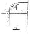
- the apparatus comprises a header tank 2 for temporarily storing liquid, a contactor column 4 suspended in a tank 6. Liquid is supplied by suitable means (not shown), such as a pump, to the header tank and is discharged on to a plane surface provided by a bridging member 8 which is initially nearly horizontal 8a but which increases in gradient to vertical 8b to merge into the top of the contactor column.
- suitable means such as a pump
- the liquid that flows down the vertical wall of the contactor column enters liquid that is already present in the column and gas is drawn in and bubbles are formed.
- the flow rate of the liquid and the cross sectional area of the contactor are proportioned such that gas bubbles are carried down by the liquid and the gas can dissolve in the liquid.
- the mass of gas dissolved depends upon these factors and increases with the height of the contactor column.
- the flowing liquid is bounded on one side by a solid surface and on the other by an interface with a gas. Whilst the solid boundary need not be a rough surface, the present invention provides a rough interface since without this no, or minimal, entrainment will take place. The rough surface drags adjacent air along and, ultimately, takes the adhering air (or gas) beneath the surface of the standing water.
- the enhanced liquid together with depleted gas bubbles can be discharged into a large body of liquid.
- the contactor column 4 may be suspended in a tank or fermenter or mounted on a floating platform on a large body of water, a pump raising liquid an appropriate rate.
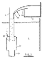
- the gas bubbles can be discharged through an orifice 20 in a separator 22, the liquid only passing through pipe 24 for discharge at some other location, as illustrated in Figure 2 of the accompanying drawings.
- the bubbles are likely to be composed of a mixture of gas introduced at the top but not dissolved, and gases generated by chemical/physical activities in the contactor column.
- the arcuate shape of the vertical side of the column causes the turbulent conditions to develop along the essentially horizontal part with minimum loss of potential energy and thus the invention is more energy efficient. It is preferred that the contactor column is a rectangular section, with fluid flowing down one face only, although flow down other faces is possible. It is to be appreciated that a circular or annular column could be used but at some loss in efficiency.
Landscapes
- Chemical & Material Sciences (AREA)
- Chemical Kinetics & Catalysis (AREA)
- Physical Or Chemical Processes And Apparatus (AREA)
- Filling Or Discharging Of Gas Storage Vessels (AREA)
Claims (23)
- Verfahren zum Begasen einer Flüssigkeit, wobei das Verfahren aufweist: Herunterlaufenlassen von zu begasendem flüssigem Einsatzmaterial an einer Oberfläche (8) in Gegenwart eines Gases und in eine stehende Flüssigkeit (6), wobei eine Seite der fließenden Flüssigkeit durch eine feste Oberfläche begrenzt wird, die durch eine Seite einer in die stehende Flüssigkeit hineinragenden Säule gebildet wird, und die andere Seite der Flüssigkeit durch eine Grenzfläche mit einem Gas begrenzt wird, das den Rest der Säule einnimmt, so daß das Gas in die stehende Flüssigkeit gesaugt wird, wobei die Bewegung des Einsatzmaterials auf der Oberfläche der Säule so beschaffen ist, daß sie Turbulenz in dem flüssigen Einsatzmaterial erzeugt, dadurch gekennzeichnet, daß man das flüssige Einsatzmaterial entlang einer Oberfläche fließen läßt, die zumindest für einen Teil seines Abwärtsflusses in die stehende Flüssigkeit mindestens eine Gefälleänderung (8a, 8b) aufweist.
- Verfahren nach Anspruch 1, wobei man das flüssige Einsatzmaterial über eine im wesentlichen horizontale Oberfläche (8a) und eine im wesentlichen vertikale Oberfläche (8b) fließen läßt, bevor es in die stehende Flüssigkeit eintritt.
- Verfahren nach Anspruch 1 oder Anspruch 2, wobei das Einsatzmaterial aus einem Behälter entnommen wird, in dem die Oberfläche so angeordnet ist, daß das begaste Einsatzmaterial von der Oberfläche in den Behälter zurückfließt.
- Verfahren nach einem der Ansprüche 1 bis 3, wobei man das Einsatzmaterial über eine Seite der Säule fließen läßt, die mindestens eine Gefälleänderung aufweist.
- Verfahren nach einem der Ansprüche 1 bis 4, wobei man das Einsatzmaterial über ein Überbrückungselement (8) fließen läßt, das mindestens eine Gefälleänderung aufweist.
- Verfahren nach einem der vorstehenden Ansprüche, wobei man das Gas direkt in den Behälter ausströmen läßt, der die stehende Flüssigkeit enthält.
- Verfahren nach einem der vorstehenden Ansprüche, das ferner die Förderung von Flüssigkeit aus dem Behälter zu der Oberfläche aufweist.
- Verfahren nach Anspruch 7, wobei die Fördereinrichtung eine Pumpe ist.
- Verfahren nach einem der vorstehenden Ansprüche, wobei das Gas Luft oder Sauerstoff zum Belüften der stehenden Flüssigkeit ist.
- Vorrichtung zum Begasen eines flüssigen Einsatzmaterials, wobei die Vorrichtung aufweist: einen Behälter zur Aufnahme von stehender Flüssigkeit (6), eine Säule (8), die in den Behälter hineinragt und so angeordnet ist, daß flüssiges Einsatzmaterial darauf aufgebracht werden kann, um zu bewirken, daß das Einsatzmaterial entlang der Säule in die stehende Flüssigkeit fließt, wobei die fließende Flüssigkeit auf einer Seite durch eine durch die Säule bereitgestellte feste Oberfläche und auf der anderen Seite durch eine Grenzfläche mit einem Gas begrenzt wird, mit dem das Einsatzmaterial begast werden soll und das den Rest der Säule einnimmt, dadurch gekennzeichnet, daß die Vorrichtung eine feste Oberfläche mit mindestens einer Gefälleänderung aufweist, über die das flüssige Einsatzmaterial fließt.
- Vorrichtung nach Anspruch 10, wobei die Gefälleänderung durch eine Oberfläche mit bogenförmigem Profil bereitgestellt wird.
- Vorrichtung nach Anspruch 10, wobei die feste Oberfläche nahe dem oder am Eintrittspunkt des flüssigen Einsatzmaterials zu der Oberfläche im wesentlichen horizontal ist und nahe dem oder am Eintrittspunkt in den Behälter im wesentlichen vertikal wird.
- Vorrichtung nach einem der Ansprüche 10 bis 12, wobei die Oberfläche mit mindestens einer Gefälleänderung durch eine Seite der Säule bereitgestellt wird.
- Vorrichtung nach einem der Ansprüche 10 bis 13, wobei die Säule rechteckig ist.
- Vorrichtung nach Anspruch 14, wobei das flüssige Einsatzmaterial einer Fläche der Säule zugeführt wird.
- Vorrichtung nach Anspruch 10, 11 oder 12, wobei die Oberfläche mit mindestens einer Gefälleänderung durch ein Überbrückungselement bereitgestellt wird.
- Vorrichtung nach einem der Ansprüche 10 bis 16, wobei ein Sammelbehälter (2) zur Aufnahme des flüssigen Einsatzmaterials vor dem Aufbringen des Einsatzmaterials auf die Oberfläche vorgesehen ist.
- Vorrichtung nach einem der Ansprüche 10 bis 17, wobei der Behälter ein Dock ist.
- Vorrichtung nach einem der Ansprüche 10 bis 17, wobei der Behälter ein Abwassertank oder Fermenter ist.
- Vorrichtung nach einem der Ansprüche 10 bis 19, die ferner eine Schwimmplattform aufweist, von der die Säule und die Oberfläche mit einer Gefälleänderung in die stehende Flüssigkeit herabhängen.
- Vorrichtung nach einem der Ansprüche 10 bis 20, wobei in einem in dem Behälter vorgesehenen Separator (22) eine Öffnung (20) zum Austritt von Blasen angebracht ist, die sich in dem flüssigen Einsatzmaterial angesammelt haben.
- Vorrichtung nach einem der Ansprüche 10 bis 21, die ferner eine Fördereinrichtung für die Zufuhr von Flüssigkeit aus dem Behälter auf die Oberfläche aufweist.
- Vorrichtung nach Anspruch 22, wobei die Fördereinrichtung eine Pumpe ist.
Applications Claiming Priority (3)
| Application Number | Priority Date | Filing Date | Title |
|---|---|---|---|
| GB0115111A GB2376642B (en) | 2001-06-21 | 2001-06-21 | Improved method and apparatus for gasifying a liquid |
| GB0115111 | 2001-06-21 | ||
| PCT/GB2002/002816 WO2003000391A1 (en) | 2001-06-21 | 2002-06-19 | Improved method and apparatus for gasifying a liquid |
Publications (2)
| Publication Number | Publication Date |
|---|---|
| EP1399247A1 EP1399247A1 (de) | 2004-03-24 |
| EP1399247B1 true EP1399247B1 (de) | 2006-04-12 |
Family
ID=9917018
Family Applications (1)
| Application Number | Title | Priority Date | Filing Date |
|---|---|---|---|
| EP02732962A Expired - Lifetime EP1399247B1 (de) | 2001-06-21 | 2002-06-19 | Verbessertes verfahren und vorrichtung zum belüften von flüssigkeiten |
Country Status (6)
| Country | Link |
|---|---|
| US (1) | US7121534B2 (de) |
| EP (1) | EP1399247B1 (de) |
| AT (1) | ATE322940T1 (de) |
| DE (1) | DE60210608T2 (de) |
| GB (1) | GB2376642B (de) |
| WO (1) | WO2003000391A1 (de) |
Families Citing this family (4)
| Publication number | Priority date | Publication date | Assignee | Title |
|---|---|---|---|---|
| US20080217226A1 (en) * | 2007-03-07 | 2008-09-11 | Porter C Bradley | Ornamental pond filter apparatus |
| CN100577583C (zh) * | 2007-08-03 | 2010-01-06 | 白冬生 | 液体注气系统 |
| GB2451870A (en) * | 2007-08-15 | 2009-02-18 | United Utilities Plc | Method and Apparatus for Aeration |
| US11980853B2 (en) * | 2021-12-01 | 2024-05-14 | Gennady Bekker | Wine aeration devices and methods of aerating wine |
Family Cites Families (28)
| Publication number | Priority date | Publication date | Assignee | Title |
|---|---|---|---|---|
| US2172646A (en) * | 1939-09-12 | Activated sludge apparatus | ||
| US1128548A (en) * | 1914-03-06 | 1915-02-16 | Henning A | Smoke-consumer. |
| US1762126A (en) * | 1927-08-25 | 1930-06-03 | Autodrink Corp | Beverage-dispensing device |
| US1905422A (en) * | 1931-01-15 | 1933-04-25 | Edvald L Rasmussen | Air conditioning apparatus |
| US2180586A (en) * | 1937-12-01 | 1939-11-21 | Binks Mfg Co | Spray booth |
| US3122126A (en) | 1961-09-12 | 1964-02-25 | Yamada Toshiroo | Fish farming equipment of many fish tanks |
| US3386229A (en) * | 1965-07-22 | 1968-06-04 | Joy Mfg Co | Apparatus and method for treatment of gases |
| DE1940458B2 (de) * | 1968-08-12 | 1972-02-17 | Miejskie Przedsiebiorstwo Wodociagow i Kanaliczacji, Czestochowa (Polen) | Verfahren und vorrichtung zum begasen einer fluessigkeit |
| US3795093A (en) * | 1972-04-27 | 1974-03-05 | Svenska Flaektfabriken Ab | Apparatus for cleaning the air from a spray painting chamber |
| US3998389A (en) * | 1972-07-19 | 1976-12-21 | Richards Of Rockford | Apparatus for gas treatment of liquids |
| US3840216A (en) * | 1972-10-26 | 1974-10-08 | Clark & Vicario Corp | Vacuum aeration of liquid waste effluent |
| DE2402181C3 (de) * | 1974-01-17 | 1979-03-29 | Energiagazdalkodasi Intezet, Budapest | Vorrichtung zur Wärme- und Stoffübertragung zwischen Flüssigkeiten und Gasen |
| US3876399A (en) * | 1974-05-08 | 1975-04-08 | Joseph P Saponaro | Eliminator section for spray booths |
| GB2079167B (en) | 1980-06-26 | 1983-12-07 | Dyson Claude | Gasifying a liquid |
| US4540528A (en) * | 1980-07-08 | 1985-09-10 | Haegeman Johny H | Apparatus for mixing gas and liquid |
| US4608064A (en) * | 1985-01-03 | 1986-08-26 | Protectaire Systems Co. | Multi-wash spray booth and method of capturing air borne particles |
| GB2185541B (en) | 1985-10-23 | 1988-10-05 | Lotus Water Garden Products Li | Waterfall |
| US4734235A (en) * | 1986-11-24 | 1988-03-29 | Holyoak H Ken | Aerator |
| US4836142A (en) * | 1986-12-08 | 1989-06-06 | Duback Clyde L | Aquarium and waterfall system |
| US4885010A (en) * | 1988-10-03 | 1989-12-05 | Gallagher-Kaiser Corporation | Spray booth |
| FR2687046B1 (fr) * | 1992-02-11 | 1994-05-20 | Ernewein Jean Michel | Dispositif portable permettant la cohabitation d'especes vegetales et animales antagonistes, dans un meme espace semi-aquatique artificiel, limite, et restreint. |
| JP2955806B2 (ja) | 1993-01-11 | 1999-10-04 | 株式会社クボタ | 滝施設 |
| FR2700484B1 (fr) * | 1993-01-18 | 1995-02-24 | Ais | Installation de peinture. |
| US5571409A (en) * | 1994-08-22 | 1996-11-05 | Scarborough; Jerry L. | Aquarium waterfall assembly |
| DE4431893C3 (de) * | 1994-09-07 | 2001-09-06 | Flaekt Ab | Naßabscheider |
| US5707562A (en) * | 1996-05-03 | 1998-01-13 | Aeration Industries International, Inc. | Turbo aerator |
| US5799609A (en) * | 1996-05-07 | 1998-09-01 | Burns; Mary V. | Animal waterer |
| GB9821097D0 (en) * | 1998-09-30 | 1998-11-18 | Weatherill Neil K | Air-decant |
-
2001
- 2001-06-21 GB GB0115111A patent/GB2376642B/en not_active Expired - Fee Related
-
2002
- 2002-06-19 WO PCT/GB2002/002816 patent/WO2003000391A1/en not_active Ceased
- 2002-06-19 DE DE60210608T patent/DE60210608T2/de not_active Expired - Fee Related
- 2002-06-19 US US10/481,493 patent/US7121534B2/en not_active Expired - Fee Related
- 2002-06-19 EP EP02732962A patent/EP1399247B1/de not_active Expired - Lifetime
- 2002-06-19 AT AT02732962T patent/ATE322940T1/de not_active IP Right Cessation
Also Published As
| Publication number | Publication date |
|---|---|
| EP1399247A1 (de) | 2004-03-24 |
| US7121534B2 (en) | 2006-10-17 |
| DE60210608D1 (de) | 2006-05-24 |
| ATE322940T1 (de) | 2006-04-15 |
| GB0115111D0 (en) | 2001-08-15 |
| GB2376642A (en) | 2002-12-24 |
| DE60210608T2 (de) | 2006-12-28 |
| GB2376642B (en) | 2005-02-02 |
| US20040183218A1 (en) | 2004-09-23 |
| WO2003000391A1 (en) | 2003-01-03 |
Similar Documents
| Publication | Publication Date | Title |
|---|---|---|
| US4931225A (en) | Method and apparatus for dispersing a gas into a liquid | |
| US4085041A (en) | Biological oxidation and flotation apparatus and method | |
| US4440645A (en) | Dissolving gas in a liquid | |
| EP0546033A4 (de) | ||
| US20110096618A1 (en) | Method and apparatus for aeration | |
| FI96388B (fi) | Menetelmä ja laitteisto kaasun liuottamiseksi | |
| CN112573653A (zh) | 一种兼具脱氮功能的内循环厌氧反应系统 | |
| US4466928A (en) | Apparatus for dissolution of gases in liquid | |
| GB1596311A (en) | Process and apparatus for the bacterial sludge treatment of aqueous waste material | |
| US7121534B2 (en) | Method and apparatus for gasifying a liquid | |
| KR20110017394A (ko) | 유체 처리 장치 | |
| EP0002369B1 (de) | Belüfter und Verfahren zum Belüften von Flüssigkeit | |
| WO1981001700A1 (en) | Method and apparatus for dissolving gas in a liquid | |
| US4452701A (en) | Biological treatment of sewage | |
| US4737282A (en) | Apparatus for separating sand and oil from a waste water stream | |
| JPH0355199B2 (de) | ||
| US11202998B2 (en) | Systems and methods for gas disposal | |
| JP3582036B2 (ja) | 気液接触装置 | |
| RU2375311C2 (ru) | Устройство безреагентной очистки воды - модуль интенсивной аэрации и дегазации (миад) | |
| JPH09118291A (ja) | 水系の浄化船 | |
| JP2008508095A (ja) | 増強されたエネルギー効率的な生物学的(廃)水処理のためのプロセスおよびリアクタ | |
| GB1559018A (en) | Method and apparatus for dissolving a gas in and removing a gas from a liquid | |
| EP3195923B1 (de) | Systeme und verfahren zur gasentsorgung | |
| KR100377020B1 (ko) | 미세기포발생장치를 이용한 폐수처리시스템 및 폐수처리방법 | |
| KR200199585Y1 (ko) | 미세기포발생장치를 이용한 폐수처리시스템 |
Legal Events
| Date | Code | Title | Description |
|---|---|---|---|
| PUAI | Public reference made under article 153(3) epc to a published international application that has entered the european phase |
Free format text: ORIGINAL CODE: 0009012 |
|
| 17P | Request for examination filed |
Effective date: 20040112 |
|
| AK | Designated contracting states |
Kind code of ref document: A1 Designated state(s): AT BE CH CY DE DK ES FI FR GB GR IE IT LI LU MC NL PT SE TR |
|
| AX | Request for extension of the european patent |
Extension state: AL LT LV MK RO SI |
|
| GRAP | Despatch of communication of intention to grant a patent |
Free format text: ORIGINAL CODE: EPIDOSNIGR1 |
|
| GRAS | Grant fee paid |
Free format text: ORIGINAL CODE: EPIDOSNIGR3 |
|
| RBV | Designated contracting states (corrected) |
Designated state(s): AT BE CH CY DE DK ES FI FR GR IE IT LI LU MC NL PT SE TR |
|
| GRAA | (expected) grant |
Free format text: ORIGINAL CODE: 0009210 |
|
| AK | Designated contracting states |
Kind code of ref document: B1 Designated state(s): AT BE CH CY DE DK ES FI FR GR IE IT LI LU MC NL PT SE TR |
|
| PG25 | Lapsed in a contracting state [announced via postgrant information from national office to epo] |
Ref country code: NL Free format text: LAPSE BECAUSE OF FAILURE TO SUBMIT A TRANSLATION OF THE DESCRIPTION OR TO PAY THE FEE WITHIN THE PRESCRIBED TIME-LIMIT Effective date: 20060412 Ref country code: AT Free format text: LAPSE BECAUSE OF FAILURE TO SUBMIT A TRANSLATION OF THE DESCRIPTION OR TO PAY THE FEE WITHIN THE PRESCRIBED TIME-LIMIT Effective date: 20060412 Ref country code: BE Free format text: LAPSE BECAUSE OF FAILURE TO SUBMIT A TRANSLATION OF THE DESCRIPTION OR TO PAY THE FEE WITHIN THE PRESCRIBED TIME-LIMIT Effective date: 20060412 Ref country code: LI Free format text: LAPSE BECAUSE OF FAILURE TO SUBMIT A TRANSLATION OF THE DESCRIPTION OR TO PAY THE FEE WITHIN THE PRESCRIBED TIME-LIMIT Effective date: 20060412 Ref country code: CH Free format text: LAPSE BECAUSE OF FAILURE TO SUBMIT A TRANSLATION OF THE DESCRIPTION OR TO PAY THE FEE WITHIN THE PRESCRIBED TIME-LIMIT Effective date: 20060412 Ref country code: FI Free format text: LAPSE BECAUSE OF FAILURE TO SUBMIT A TRANSLATION OF THE DESCRIPTION OR TO PAY THE FEE WITHIN THE PRESCRIBED TIME-LIMIT Effective date: 20060412 Ref country code: IT Free format text: LAPSE BECAUSE OF FAILURE TO SUBMIT A TRANSLATION OF THE DESCRIPTION OR TO PAY THE FEE WITHIN THE PRESCRIBED TIME-LIMIT;WARNING: LAPSES OF ITALIAN PATENTS WITH EFFECTIVE DATE BEFORE 2007 MAY HAVE OCCURRED AT ANY TIME BEFORE 2007. THE CORRECT EFFECTIVE DATE MAY BE DIFFERENT FROM THE ONE RECORDED. Effective date: 20060412 |
|
| REG | Reference to a national code |
Ref country code: CH Ref legal event code: EP |
|
| REF | Corresponds to: |
Ref document number: 60210608 Country of ref document: DE Date of ref document: 20060524 Kind code of ref document: P |
|
| REG | Reference to a national code |
Ref country code: IE Ref legal event code: FG4D |
|
| PG25 | Lapsed in a contracting state [announced via postgrant information from national office to epo] |
Ref country code: IE Free format text: LAPSE BECAUSE OF NON-PAYMENT OF DUE FEES Effective date: 20060619 |
|
| PG25 | Lapsed in a contracting state [announced via postgrant information from national office to epo] |
Ref country code: MC Free format text: LAPSE BECAUSE OF NON-PAYMENT OF DUE FEES Effective date: 20060630 |
|
| PG25 | Lapsed in a contracting state [announced via postgrant information from national office to epo] |
Ref country code: DK Free format text: LAPSE BECAUSE OF FAILURE TO SUBMIT A TRANSLATION OF THE DESCRIPTION OR TO PAY THE FEE WITHIN THE PRESCRIBED TIME-LIMIT Effective date: 20060712 Ref country code: SE Free format text: LAPSE BECAUSE OF FAILURE TO SUBMIT A TRANSLATION OF THE DESCRIPTION OR TO PAY THE FEE WITHIN THE PRESCRIBED TIME-LIMIT Effective date: 20060712 |
|
| PG25 | Lapsed in a contracting state [announced via postgrant information from national office to epo] |
Ref country code: ES Free format text: LAPSE BECAUSE OF FAILURE TO SUBMIT A TRANSLATION OF THE DESCRIPTION OR TO PAY THE FEE WITHIN THE PRESCRIBED TIME-LIMIT Effective date: 20060723 |
|
| PG25 | Lapsed in a contracting state [announced via postgrant information from national office to epo] |
Ref country code: PT Free format text: LAPSE BECAUSE OF FAILURE TO SUBMIT A TRANSLATION OF THE DESCRIPTION OR TO PAY THE FEE WITHIN THE PRESCRIBED TIME-LIMIT Effective date: 20060912 |
|
| NLV1 | Nl: lapsed or annulled due to failure to fulfill the requirements of art. 29p and 29m of the patents act | ||
| REG | Reference to a national code |
Ref country code: CH Ref legal event code: PL |
|
| ET | Fr: translation filed | ||
| PLBE | No opposition filed within time limit |
Free format text: ORIGINAL CODE: 0009261 |
|
| STAA | Information on the status of an ep patent application or granted ep patent |
Free format text: STATUS: NO OPPOSITION FILED WITHIN TIME LIMIT |
|
| 26N | No opposition filed |
Effective date: 20070115 |
|
| PGFP | Annual fee paid to national office [announced via postgrant information from national office to epo] |
Ref country code: DE Payment date: 20070614 Year of fee payment: 6 |
|
| PG25 | Lapsed in a contracting state [announced via postgrant information from national office to epo] |
Ref country code: GR Free format text: LAPSE BECAUSE OF FAILURE TO SUBMIT A TRANSLATION OF THE DESCRIPTION OR TO PAY THE FEE WITHIN THE PRESCRIBED TIME-LIMIT Effective date: 20060713 |
|
| PGFP | Annual fee paid to national office [announced via postgrant information from national office to epo] |
Ref country code: FR Payment date: 20070608 Year of fee payment: 6 |
|
| PG25 | Lapsed in a contracting state [announced via postgrant information from national office to epo] |
Ref country code: LU Free format text: LAPSE BECAUSE OF NON-PAYMENT OF DUE FEES Effective date: 20060619 Ref country code: TR Free format text: LAPSE BECAUSE OF FAILURE TO SUBMIT A TRANSLATION OF THE DESCRIPTION OR TO PAY THE FEE WITHIN THE PRESCRIBED TIME-LIMIT Effective date: 20060412 |
|
| PG25 | Lapsed in a contracting state [announced via postgrant information from national office to epo] |
Ref country code: CY Free format text: LAPSE BECAUSE OF FAILURE TO SUBMIT A TRANSLATION OF THE DESCRIPTION OR TO PAY THE FEE WITHIN THE PRESCRIBED TIME-LIMIT Effective date: 20060412 |
|
| REG | Reference to a national code |
Ref country code: FR Ref legal event code: ST Effective date: 20090228 |
|
| PG25 | Lapsed in a contracting state [announced via postgrant information from national office to epo] |
Ref country code: DE Free format text: LAPSE BECAUSE OF NON-PAYMENT OF DUE FEES Effective date: 20090101 |
|
| PG25 | Lapsed in a contracting state [announced via postgrant information from national office to epo] |
Ref country code: FR Free format text: LAPSE BECAUSE OF NON-PAYMENT OF DUE FEES Effective date: 20080630 |