EP1398515A2 - Tragkonstruktion - Google Patents
Tragkonstruktion Download PDFInfo
- Publication number
- EP1398515A2 EP1398515A2 EP03020968A EP03020968A EP1398515A2 EP 1398515 A2 EP1398515 A2 EP 1398515A2 EP 03020968 A EP03020968 A EP 03020968A EP 03020968 A EP03020968 A EP 03020968A EP 1398515 A2 EP1398515 A2 EP 1398515A2
- Authority
- EP
- European Patent Office
- Prior art keywords
- contact surface
- connector
- tube
- structure according
- pipes
- Prior art date
- Legal status (The legal status is an assumption and is not a legal conclusion. Google has not performed a legal analysis and makes no representation as to the accuracy of the status listed.)
- Withdrawn
Links
- 229920001903 high density polyethylene Polymers 0.000 claims abstract description 6
- 229920003023 plastic Polymers 0.000 claims abstract description 5
- 239000004033 plastic Substances 0.000 claims abstract description 5
- 238000010276 construction Methods 0.000 claims abstract description 4
- 239000002131 composite material Substances 0.000 claims description 7
- 238000004519 manufacturing process Methods 0.000 claims description 7
- 229910052751 metal Inorganic materials 0.000 claims description 3
- 239000002184 metal Substances 0.000 claims description 3
- 229910000737 Duralumin Inorganic materials 0.000 claims description 2
- 239000000969 carrier Substances 0.000 claims 1
- 238000003754 machining Methods 0.000 claims 1
- 230000000149 penetrating effect Effects 0.000 claims 1
- 239000000463 material Substances 0.000 abstract description 2
- 239000004700 high-density polyethylene Substances 0.000 abstract 1
- 229910000831 Steel Inorganic materials 0.000 description 2
- 239000004744 fabric Substances 0.000 description 2
- 239000010959 steel Substances 0.000 description 2
- TVEXGJYMHHTVKP-UHFFFAOYSA-N 6-oxabicyclo[3.2.1]oct-3-en-7-one Chemical compound C1C2C(=O)OC1C=CC2 TVEXGJYMHHTVKP-UHFFFAOYSA-N 0.000 description 1
- 229910000838 Al alloy Inorganic materials 0.000 description 1
- 229910001335 Galvanized steel Inorganic materials 0.000 description 1
- 230000006750 UV protection Effects 0.000 description 1
- 208000027418 Wounds and injury Diseases 0.000 description 1
- 238000005299 abrasion Methods 0.000 description 1
- 239000000853 adhesive Substances 0.000 description 1
- 230000001070 adhesive effect Effects 0.000 description 1
- 229910052782 aluminium Inorganic materials 0.000 description 1
- XAGFODPZIPBFFR-UHFFFAOYSA-N aluminium Chemical compound [Al] XAGFODPZIPBFFR-UHFFFAOYSA-N 0.000 description 1
- 238000005452 bending Methods 0.000 description 1
- 238000005260 corrosion Methods 0.000 description 1
- 230000007797 corrosion Effects 0.000 description 1
- 230000006378 damage Effects 0.000 description 1
- 238000011161 development Methods 0.000 description 1
- 230000018109 developmental process Effects 0.000 description 1
- 239000008397 galvanized steel Substances 0.000 description 1
- 208000014674 injury Diseases 0.000 description 1
- 230000001788 irregular Effects 0.000 description 1
- 238000000034 method Methods 0.000 description 1
- 230000004048 modification Effects 0.000 description 1
- 238000012986 modification Methods 0.000 description 1
- 238000007790 scraping Methods 0.000 description 1
- IHQKEDIOMGYHEB-UHFFFAOYSA-M sodium dimethylarsinate Chemical class [Na+].C[As](C)([O-])=O IHQKEDIOMGYHEB-UHFFFAOYSA-M 0.000 description 1
Images





Classifications
-
- E—FIXED CONSTRUCTIONS
- E04—BUILDING
- E04B—GENERAL BUILDING CONSTRUCTIONS; WALLS, e.g. PARTITIONS; ROOFS; FLOORS; CEILINGS; INSULATION OR OTHER PROTECTION OF BUILDINGS
- E04B1/00—Constructions in general; Structures which are not restricted either to walls, e.g. partitions, or floors or ceilings or roofs
- E04B1/38—Connections for building structures in general
- E04B1/58—Connections for building structures in general of bar-shaped building elements
- E04B1/5825—Connections for building structures in general of bar-shaped building elements with a closed cross-section
- E04B1/5837—Connections for building structures in general of bar-shaped building elements with a closed cross-section of substantially circular form
-
- E—FIXED CONSTRUCTIONS
- E04—BUILDING
- E04B—GENERAL BUILDING CONSTRUCTIONS; WALLS, e.g. PARTITIONS; ROOFS; FLOORS; CEILINGS; INSULATION OR OTHER PROTECTION OF BUILDINGS
- E04B1/00—Constructions in general; Structures which are not restricted either to walls, e.g. partitions, or floors or ceilings or roofs
- E04B1/18—Structures comprising elongated load-supporting parts, e.g. columns, girders, skeletons
- E04B1/28—Structures comprising elongated load-supporting parts, e.g. columns, girders, skeletons the supporting parts consisting of other material
-
- F—MECHANICAL ENGINEERING; LIGHTING; HEATING; WEAPONS; BLASTING
- F16—ENGINEERING ELEMENTS AND UNITS; GENERAL MEASURES FOR PRODUCING AND MAINTAINING EFFECTIVE FUNCTIONING OF MACHINES OR INSTALLATIONS; THERMAL INSULATION IN GENERAL
- F16B—DEVICES FOR FASTENING OR SECURING CONSTRUCTIONAL ELEMENTS OR MACHINE PARTS TOGETHER, e.g. NAILS, BOLTS, CIRCLIPS, CLAMPS, CLIPS OR WEDGES; JOINTS OR JOINTING
- F16B7/00—Connections of rods or tubes, e.g. of non-circular section, mutually, including resilient connections
- F16B7/18—Connections of rods or tubes, e.g. of non-circular section, mutually, including resilient connections using screw-thread elements
-
- A—HUMAN NECESSITIES
- A63—SPORTS; GAMES; AMUSEMENTS
- A63B—APPARATUS FOR PHYSICAL TRAINING, GYMNASTICS, SWIMMING, CLIMBING, OR FENCING; BALL GAMES; TRAINING EQUIPMENT
- A63B9/00—Climbing poles, frames, or stages
- A63B2009/006—Playground structures
-
- A—HUMAN NECESSITIES
- A63—SPORTS; GAMES; AMUSEMENTS
- A63B—APPARATUS FOR PHYSICAL TRAINING, GYMNASTICS, SWIMMING, CLIMBING, OR FENCING; BALL GAMES; TRAINING EQUIPMENT
- A63B2208/00—Characteristics or parameters related to the user or player
- A63B2208/12—Characteristics or parameters related to the user or player specially adapted for children
-
- E—FIXED CONSTRUCTIONS
- E04—BUILDING
- E04B—GENERAL BUILDING CONSTRUCTIONS; WALLS, e.g. PARTITIONS; ROOFS; FLOORS; CEILINGS; INSULATION OR OTHER PROTECTION OF BUILDINGS
- E04B1/00—Constructions in general; Structures which are not restricted either to walls, e.g. partitions, or floors or ceilings or roofs
- E04B1/38—Connections for building structures in general
- E04B1/58—Connections for building structures in general of bar-shaped building elements
- E04B2001/5868—Hinged connections
Definitions
- the invention relates to a supporting structure in the preamble of claim 1 explained Art.
- Such a supporting structure is known from DE 200 135 44 U.
- the well-known The supporting structure is made of plastic pipes, in particular of PE-HD, which were on the market for the manufacture of pipelines, but for construction purposes were used.
- the pipes needed to build the known one Supporting structure are laboriously welded.
- the invention is therefore based on the object of a supporting structure with an improved To create connection between the pipes.
- the connector set according to the invention contains at least a first type of connector, which is provided with a first contact surface for a first tube, and the one includes additional contact surface and fasteners that connect the connector directly attach to the pipe. This ensures a secure, durable connection that all safety regulations are sufficient, especially when used for play or Leisure equipment is very strict.
- the second contact surface can either be used as an additional contact surface for another Pipe, to be placed either on the inside or the outside of the pipe, be formed, or it can be used as a clamping surface for application to a clamping piece be formed, with accessories such as nets or towels or with the clamping piece Ropes can be attached, or it can be designed as a support, the The connector then acts as a floor support.
- Figure 1 is a preferred embodiment of a support structure according to the invention 1 can be seen, which is designed here as a play and leisure device.
- the supporting structure 1 forms a rise for a slide or the like. For children's playgrounds, in particular outdoors.
- the support structure 1 was created with pipes, such as those used for manufacturing of conduits are on the market.
- Plastic pipes are particularly useful, in particular PE-HD, which is used constructively according to the teaching of DE 200 135 44 U. and have proven to be weatherproof and indestructible for these purposes to have.
- the supporting structure 1 can also be made entirely or partially from composite pipes be created, which consist of an inner tube and an outer tube, the Production is explained in more detail below.
- the support frame 1 is made up of a large number of appropriately cut tubes 2 erected, depending on the intended use pipes with different diameters and / or different wall thicknesses can be used. Furthermore are with the tubes 2 accessories, such as a plate 3 for a tread or a roof or a covering 4 in the form of a cloth or a net combined. All these parts are mechanically interconnected by a connector set 5 connected, the components of which are explained in more detail below.
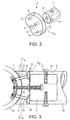
- the connector set 5 contains a first connector 6 (FIGS. 2 and 3), which is used to manufacture a T-connection between two pipes 2 is formed.
- the connector 6 contains for this purpose, a first contact surface 7 on a preferably disk or plate-shaped Base part 8, wherein the contact surface 7 as part of a cylindrical surface with the radius of curvature the outside of a tube 2 is curved inwards, so that the contact surface 7 as an external contact surface for a full-surface contact of the base part 8 on the outside a tube 2 is formed. Extends in the circumferential direction of the tube 2 the contact surface 7 over about a quarter circle.
- the base part 8 is radial of three for the curvature of the contact surface 7 extending rivet holes 9 and also one radially extending, preferably threaded center hole 10 penetrates.
- the base part 8 can have cylindrical side faces 8a or, as shown in dashed lines in Fig. 3, with more or less oblique as required Side surfaces 8b or 8'b may be provided, so that several base parts 8 .mu.m the circumference of the tube 2a closely adjacent, abutting, are attached can.
- the side surfaces 8b preferably run radially to the radius of curvature of the contact surface 7th
- the connector 6 also contains a holding part 12, preferably in the form of a cylinder, which carries a further outwardly curved contact surface 11 on its outer circumference, which is also designed as a cylinder or partial cylinder surface, the diameter is adapted to the inner width of the tubes 2, so that the contact surface 11 over the entire surface can lie against the inside of a pipe.
- the holding part 12 is axially from a mounting hole 13 penetrates, which can be aligned with the center bore 10. Radial the holding part 12 is penetrated by at least one bore 14, which is the attachment the tube 2 is used.
- the connector 6 is used for the T connection between a first tube 2a with a second tube 2b opposite the first pipe 2a has a slightly smaller, preferably a nominal dimension smaller, outer and has inside width. However, the connector 6 can also be used when both pipes 2a, 2b are the same size or the pipe 2b is larger than the pipe 2a.
- the base part 8 is made using a total of 15 designated fasteners attached to the outside of the tube 2a.
- the Fasteners preferably contain blind rivets 16, especially those specifically illustrated, commercially available peeling rivets or expanding blind rivets.
- the blind rivets 16 are inserted into the rivet holes 9 and driven through the wall of the tube 2a. When the rivets are set, the free ends spread out inside the tube 2a and anchor the base part 8 captively and immovably on the wall of the tube 2a.
- the center hole 10 is either a modified blind rivet with an internal thread set or the opening 10 is itself threaded.
- the holding part 12 attached via the axial central bore 13 so that the Inner contact surface 11 for establishing a 90 ° T connection perpendicular to the contact surface 7 extends.
- holding parts 12 with a beveled end face can other angle connections can also be realized.
- Figure 4 shows a further connector 18, which both the connector 6 within the Can replace connector set 5, but also provided in addition to the connector 6 can be.
- the connector 18 is formed in one piece and block-shaped and contains in turn, the contact surface 7 designed as part of a cylinder for application to the Outside of the tube 2, which is formed analogously to the contact surface 7 of the connector 6 is.
- the connector 18 further contains two partially cylindrical contact surfaces 11a and 11b, those for contact to the inside of a tube 2, analogous to the circular cylindrical inner contact surface of the connector 6, are formed.
- the block-shaped connector 18 is of a first bore 19, which opens into the outer contact surface 7, and a second Bore 20 which penetrates into the inner contact surfaces 11a, 11b.
- the connector 18 with its outer contact surface is first 7 attached to the outside of a first tube 2a.
- the attachment can, as in the first embodiment, by fasteners 15 in the form of blind rivets 16 extending through the raw wall.
- the attachment can but also, as FIG. 5 shows, by a diametrically extending tube 2a and secured on the side opposite the connector 18 by a nut Screw.
- the second tube 2b is in turn fastened by two screws 17 which extend through the wall of the tube 2b and into the threaded holes 20 of the connector 18 are received.
- FIG. 7 shows a further connector 21 of the connector set 5, which essentially is formed similar to the base part 8 of the first connector 6. In fact, it can Connector 21 can be used in place of the base part 8 of the connector 6, which is the Reducing the number of parts of the connector set kept in stock helps.
- the connector 21 is also plate-shaped or disk-shaped and contains on one side the outer contact surface 7 already described, which of the rivet holes 9 and Center hole 10 is penetrated. At the opposite of the curved outer contact surface 7 One side is the plate - or disk - shaped connector 21 with another provided inwardly curved contact surface 22 for the outside of a tube.
- the Outer contact surface 22 extends parallel to the outer contact surface 7 on the other Side of the connector 21, so that, as Figure 8 shows, two tubes 2a, 2b connected in parallel can be.
- the contact surface 22 is with a smaller radius of curvature for receiving a tube 2b with a smaller one Outside diameter formed as the tube 2a, which bears on the outer contact surface 7.
- the contact surfaces 7, 22 can also be at an angle of 90 ° to one another be offset to allow a 90 ° cross connection of two pipes. Other Crossing angles are possible.
- the connector 21 can be used with both Pipes through a single pipe, through the wall of both pipes and through the center hole 10 extending screw 17 are connected. However, it is preferred that first the connector 21 on the first tube 2a via fastening elements 15 in shape attached by blind rivets and only then the second pipe 2b over the threaded Center bore 10 is screwed.
- FIG. 9 A wide use of the connector 21 is shown in FIG. 9.
- the outer contact surface 22 serves the outer contact surface 22 as a clamping surface for clamping one Attachment loop 23 of a cloth or a net or the like over a Rod 24, which is pushed into the fastening loop 23 and with the aid of fastening elements, is shown, a screw 17 is attached to the connector 21.
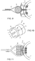
- FIG. 10 shows a further connector 25 which has a first base part 26 which is connected to the outer contact surface 7, the rivet holes 9 and the central bore 10 analog the base part 8 of the connector 6 is formed.
- the one opposite the outer contact surface 7 Side of the plate-shaped or disk-shaped part 26 is as a clamping surface 27 formed which cooperates with an end face 28 of a clamping piece 29, which with a central bore 29 is provided which is in contact with the central bore 10 on the base part 26 can be aligned.
- the mutually facing clamping surfaces 27, 28 can be provided with corresponding receiving grooves, as shown in Figure 11 is.
- the clamping piece 29 can also be designed as a bar with several Share 26 interacts.
- the connector 25 is also used for clamping fastening loops 23 used, which are looped around the clamping piece 29, to this Purpose has rounded edges.
- FIG. 12 shows a further connector 30, which is used to make miter connections, d. H. butt connections of two pipes 2a, 2b at a predetermined miter angle ⁇ , for example 45 ° or 60 °, is used.
- the miter connector 30 contains two parts 30a, 30b, which are strip-shaped and two each below the miter angle ⁇ butting each other, provided with rivet or screw holes Have legs 31a, 31b, 33a, 33b.
- the legs of each part 30a, 30b are bent from flat material or have a corresponding to the angle of curvature of the
- the inside of the pipes 2a, 2b to be connected has a curved inner contact surface.
- the legs 31a, 31b are composed such that the miter angle ⁇ occurs between their broad sides, so that the part 30 a in the outer and / or inner vertex of the miter fits (see Figure 13).
- the legs 33a, 33b are the legs 33a, 33b, so composed that the miter angle ⁇ between the narrow sides occurs, so that the part 30c, as shown in Figure 13 for connecting the tubes 2a, 2b can be inserted between the two vertices of the miter.
- two of the parts 30a, 30b are provided.
- the flat, strip-shaped parts 30a, 30b each have two contact surfaces or edges 32, 34 on the inside of the tubes 2.
- FIG. 14 shows a further connector 35, which in the exemplary embodiment shown as Floor support is formed.
- the connector 35 is also strip-shaped and includes a first leg 36a and a second leg 36b.
- the first Leg 36a is provided with an outer contact surface 37, which is formed by bending the first Leg 36a with the radius of curvature of the outer diameter of the tube 2nd takes place in such a way that the leg 36a can lie against the pipe 2 in the circumferential direction.
- Rivet holes 9 for attaching the connector 35 are preferably provided in the leg 36a With the help of the previously described blind rivets 16 on the tube 2.
- the second Leg 36b of the connector 35 forms a support for a plate 3, preferably by a screw connection 17 is fastened.
- the connectors are preferably made of metal, in particular aluminum; can however can also be made from a plastic.
- FIG. 16 and 17 show another connector 40 which is similar to connector 6 is trained, i.e. has a base part 41 and a holding part 42 fastened to the base part 41.
- the base part 41 is preferably disc-shaped or plate-shaped and with an outer bearing surface 43, with which the base part 41 on the outer circumference of a the first tube 2a and there with the help of the screws or Rivets is attached.
- the holding part 42 is also with the cylindrical or partially cylindrical, or other inner contact surface adapted to the inner circumference of the second tube 2b 44 and with the base part 41 via a pivot axis 45 connected.
- the pivot axis 45 is preferably a pin which the holding part 42 and the Base part 41 pivotally connected.
- the holding part 42 is on its end facing the base part 41 is provided with a slot 46 into which one from the base part 41 protruding tab 47 is received so that the Pivot pin 45 can extend through both parts.
- the base part 41 facing The end of the holding part 42 is rounded with the swivel radius, so that the holding part 42 essentially over a swivel angle of approximately 180 ° with respect to the base part 41 can pivot freely.
- the pivot pin 45 extends parallel to one Tangent to the first tube 2a, so that the two tubes 2a, 2b in one Can be connected horizontally.
- the swivel pin extends 45 parallel to the axis of the first tube 2a, angled cross connections are possible.
- the connector 40 has the advantage that here the crossing angle between the two Pipes 2a and 2b is not specified.
- the pipe to be connected in this case that second tube 2b, must only be cut off at the desired angle and must attached to the holding part 42 with the usual screw or with other fastening means , whereby the connector 40 adapts to exactly this angle.
- Too too to get a smooth connection of the pipe 2b to the connector 40 is also here the base part 41 is provided with a support surface 48 which is so large that the cut one The end face of the second tube 2b lies smoothly and in alignment.
- Angular connections for example to the pentagon, to the hexagon or the like, but also Completely irregular angle connections can be realized without having to do so for each angle a connector must be kept in stock. Also inevitable manufacturing tolerances can be easily compensated.
- the composite tube consists of an outer tube 50 and at least one inner tube 51.
- the outer tube 50 was, for example, with regard to the loads at the site with regard to UV resistance, weather resistance, corrosion resistance and selected for a low risk of injury, the outer tube 50 is preferably a PE-HD pipe, as is also the case in the other exemplary embodiments is preferred.
- the inner tube 51 was increased in particular in view of an Strength selected and preferably consists of metal, e.g. hot-dip galvanized steel or an aluminum alloy such as duralumin. Because commercially available pipes A new process was developed only with regard to its outer diameter developed for the production of composite pipes.
- the inside diameter of the outer tube 50 expanded to the outer diameter of the inner tube 51 happens.
- a correspondingly adapted cutting tool pulled through the outer tube 50 is pulled in, this with the simplest means, for example with a steel cable and a heavy-duty winch can be carried out.
- the two pipes are of the same height and one behind the other arranged, the steel cable is pulled through both pipes and at the end of the Anchored inner tube, this being done for example by a stepped cylinder can, the different in different inner diameters of the inner tube Steps and one lying against the wall thickness of the inner tube at the free end Includes traction area.
- the inner tube is from the front end of the outer tube pulled into the outer tube, the cutting set coupled to the inner tube can be.
- pipe lengths can be reduced of composite pipes up to 1200 cm in part.
- the inside diameter of the outer tube 50 is preferably only expanded to such an extent that the inner tube positive, i.e. by press or friction fit, holds in the outer tube 50 so that additional fasteners are unnecessary. If necessary, the connection of the two pipes still through connectors, screws or rivets, adhesives or Like. Be improved.
- the Connector to the external circumstances in particular to the dimensions and the Cross-sectional shapes of the pipes or pipe profiles and the angles of the desired connections be adjusted.
- the connector set can be less than the specified variety the connector when certain connectors are not needed.
- the supporting structure according to the invention can also be used by others for play and leisure equipment Purposes, for example to set up exhibition stands or the like.
- Miter connectors can also be a combined inner and outer sleeve with a Inside-outside contact surface or a pure outer sleeve or a pure inner sleeve is used become.
Landscapes
- Engineering & Computer Science (AREA)
- Architecture (AREA)
- Physics & Mathematics (AREA)
- Electromagnetism (AREA)
- Civil Engineering (AREA)
- Structural Engineering (AREA)
- General Engineering & Computer Science (AREA)
- Mechanical Engineering (AREA)
- Mutual Connection Of Rods And Tubes (AREA)
- Joining Of Building Structures In Genera (AREA)
- Supports For Pipes And Cables (AREA)
Abstract
Description
- Fig. 1
- eine schematische Darstellung eines beispielhaften, erfindungsgemäßen Tragegerüsts,
- Fig. 2
- eine perspektivische, schematische Darstellung eines ersten Verbinders,
- Fig. 3
- die Darstellung einer Verwendung des Verbinders nach Figur 2,
- Fig. 4
- eine schematische, perspektivische Darstellung eines weiteren Verbinders,
- Fig. 5
- die Darstellung einer Verwendung des Verbinders nach Figur 4 in Seitenansicht,
- Fig. 6
- eine Draufsicht auf Figur 5,
- Fig. 7
- eine schematische, perspektivische Darstellung eines weiteren Verbinders,
- Fig. 8
- eine Darstellung einer Verwendung des Verbinders nach Figur 7,
- Fig. 9
- eine Darstellung einer weiteren Verwendung des Verbinders nach Figur 7,
- Fig. 10
- eine schematische, perspektivische Darstellung eines weiteren Verbinders,
- Fig. 11
- eine Darstellung einer Verwendung des Verbinders nach Figur 10,
- Fig. 12
- eine schematische, perspektivische Darstellung eines weiteren Verbinders,
- Fig. 13
- eine Darstellung einer Verwendung des Verbinders nach Figur 12,
- Fig. 14
- eine schematische, perspektivische Darstellung eines weiteren Verbinders,
- Fig. 15
- eine Darstellung einer Verwendung des Verbinders nach Figur 14,
- Fig. 16
- eine geschnittene Seitenansicht eines weiteren Verbinders, und
- Fig. 17
- die Vorderansicht auf Fig. 16.
Claims (26)
- Tragkonstruktion (1 ) mit einer Mehrzahl von als Hohlprofilen, insbesondere als Rohre (2) ausgebildeten Trägern, insbesondere aus Kunststoff, sowie einem Verbindersatz (5), der wenigstens einen Verbinder (6, 18, 21, 25, 30, 35, 40) mit einer ersten Anlagefläche (7, 32, 37, 42) für ein erstes Rohr (2), einer zweiten Anlagefläche (11, 11a, 11b, 22, 27, 34, 36b, 44) und Befestigungselementen (15) zum Befestigen des Verbinders am Rohr (2) umfasst.
- Tragkonstruktion nach Anspruch 1, dadurch gekennzeichnet, dass die erste Anlagefläche eine Außenanlagefläche (7, 37, 43) zur Anlage an die Außenseite des Rohres ist.
- Tragkonstruktion nach Anspruch 1 oder 2, dadurch gekennzeichnet, dass sich die erste und die zweite Anlagefläche im Winkel zueinander erstrecken.
- Tragkonstruktion nach einem der Ansprüche 1 bis 3, dadurch gekennzeichnet, dass die erste Anlagefläche (7, 34, 37, 43) eine Zylinderfläche mit einem für eine flächige Anlage an die Krümmung des Rohres (2) angepassten Krümmungsradius ist.
- Tragkonstruktion nach einem der Ansprüche 1 bis 4, dadurch gekennzeichnet, dass die zweite Anlagefläche (11, 11a, 11b, 22, 34, 44) zur Anlage an einem zweiten Rohr (2) ausgebildet ist.
- Tragkonstruktion nach Anspruch 5, dadurch gekennzeichnet, dass die zweite Anlagefläche (11, 11a, 11b, 22, 34, 44) eine Zylinderfläche mit einem für eine flächige Anlage an die Krümmung des Rohres (2) angepassten Krümmungsradius ist.
- Tragkonstruktion nach einem der Ansprüche 1 bis 6, dadurch gekennzeichnet, dass die erste Anlagefläche (7, 43) eine Außen-Anlagefläche für eine Außenseite des Rohres (2) und die zweite Anlagefläche (11, 11a, 11b, 44) eine Innen-Anlagefläche für eine Innenseite des zweiten Rohres (2) ist.
- Tragkonstruktion nach einem der Ansprüche 1 bis 7, dadurch gekennzeichnet, dass der Verbinder (6, 21, 25, 40) ein scheiben - oder plattenförmiges Basisteil (8, 21, 26, 41) umfasst, wobei die erste, als Außen-Anlagefläche ausgebildete Anlagefläche (7, 43) an einer Seite vorgesehen ist.
- Tragkonstruktion nach Anspruch 8, dadurch gekennzeichnet, dass der Verbinder (6) ein Halteteil (12) umfasst, das mit der zweiten, als Innen-Anlagefläche ausgebildeten Anlagefläche (11) versehen ist und lösbar an der anderen Seite des Basisteils (8) befestigt ist.
- Tragkonstruktion nach Anspruch 8, dadurch gekennzeichnet, dass der Verbinder ein Halteteil (42) umfasst, das mit der zweiten, als Innenanlagefläche ausgebildeten Anlagefläche (44) versehen ist und schwenkbar an der anderen Seite des Basisteils (48) befestigt ist.
- Tragkonstruktion nach Anspruch 8, dadurch gekennzeichnet, dass die andere Seite des scheiben- oder plattenförmigen Basisteils (21) mit einer Außen-Anlagefläche (22) für ein weiteres Rohr (2) versehen ist.
- Tagkonstruktion nach Anspruch 8, dadurch gekennzeichnet, dass die andere Seite des scheiben- oder plattenförmigen Basisteils (21, 26) mit einer als Klemmfläche (22, 27) ausgebildeten Anlagefläche versehen ist, an der ein Klemmstück (24, 29) lösbar zu befestigen ist.
- Tragkonstruktion nach einem der Ansprüche 1 bis 7; dadurch gekennzeichnet, dass der Verbinder (18) blockförmig ausgebildet ist und jeweils eine Außen- und eine Innen- Anlagefläche (7, 11a, 11b) für jeweils ein Rohr (2) aufweist.
- Tragkonstruktion nach einem der Ansprüche 1 bis 13, gekennzeichnet durch einen weiteren Verbinder (30) zum Verbinden zweier Rohre (2) auf Gehrung, der zwei Innen-Anlageflächen (34) für Rohre (2) aufweist.
- Tragkonstruktion nach einem der Ansprüche 1 bis 14., gekennzeichnet durch weitere Zubehör-Verbinder (35).
- Tragkonstruktion nach Anspruch 15, gekennzeichnet durch einen als Bodenträger ausgebildeten Zubehör-Verbinder (35), der eine Außen-Anlagefläche (37) für ein Rohr (2) und ein Auflager (36b) umfasst.
- Tragkonstruktion nach einem der Ansprüche 1 bis 16, gekennzeichnet durch die Rohrwand durchdringende Befestigungselemente in Form von Nieten (16), insbesondere von Blind- bzw. Schälnieten, und /oder Befestigungselemente (15) in Form von Schrauben (17) vorgesehen sind.
- Tragkonstruktion nach einem der Ansprüche 1 bis 17, gekennzeichnet durch die Verwendung von PE-HD-Rohren (2).
- Tragkonstruktion nach einem der Ansprüche 1 bis 17, gekennzeichnet durch die Verwendung von Composite-Rohren (2), insbesondere mit einem Außenrohr (50) aus PE-HD- und einem Innenrohr (51) aus Metall, insbesondere Duralumin.
- Tragkonstruktion nach einem der Ansprüche 1 bis 19, gekennzeichnet durch seine Verwendung zum Aufbau eines Spiel- oder Freizeitgerätes.
- Verbinder (6, 18) für eine Tragkonstruktion aus einer Mehrzahl von Rohren, nach einem der Ansprüche 1 bis 20, gekennzeichnet durch eine Außen-Anlagefläche (7) für ein Rohr (2), eine Innen-Anlagefläche (11a, 11b) für ein Rohr (2) und Befestigungselemente (15) zum Befestigen der Rohre (2) an den Anlageflächen (7, 11, 11a, 11b) durch die Rohrwand hindurch.
- Verbinder (21) für eine Tragkonstruktion aus einer Mehrzahl von Rohren nach einem der Ansprüche 1 bis 20, gekennzeichnet durch zwei Außen-Anlageflächen (7, 22) für Rohre (2) und Befestigungselemente (15) zum Befestigen der Rohre (2) durch die Rohrwandung hindurch.
- Verbinder (21, 25) für eine Tragkonstruktion aus einer Mehrzahl von Rohren nach einem der Ansprüche 1 bis 20, gekennzeichnet durch eine Außen-Anlagefläche (7) und eine Klemmfläche (22, 27) für ein Klemmstück (24, 29) sowie mit Befestigungselementen (15) zum Befestigen des Verbinders am Rohr durch die Rohrwandung hindurch und zum Befestigen des Klemmstücks (24, 29) an der Klemmfläche.
- Verbinder (30) für eine Tragkonstruktion aus einer Mehrzahl von Rohren nach einem der Ansprüche 1 bis 20, gekennzeichnet durch zwei in einem Gehrungswinkel (α) zueinander verlaufenden Innen-Anlageflächen (34) sowie mit Befestigungselementen (15) zum Befestigen des Verbinders (30) an zwei Rohren (2).
- Verbinder (35) für eine Tragkonstruktion aus einer Mehrzahl von Rohren nach einem der Ansprüche 1 bis 20, gekennzeichnet durch eine Außen-Anlagefläche (37) für ein Rohr (2) und ein Auflager (36b) sowie mit Befestigungselementen (15) zum Befestigen des Verbinders (35) am Rohr (2) durch die Wandung des Rohres hindurch.
- Verfahren zum Herstellen von Composite-Rohren (2) gemäß Anspruch 19, wobei der Innendurchmesser des Außenrohres (50) mechanisch, insbesondere spanabhebend, auf den Außendurchmesser des Innenrohres (51) aufgeweitet und Innenrohr (51) und Außenrohr (50) übereinandergezogen werden.
Applications Claiming Priority (2)
| Application Number | Priority Date | Filing Date | Title |
|---|---|---|---|
| DE20214307U | 2002-09-16 | ||
| DE20214307U DE20214307U1 (de) | 2002-09-16 | 2002-09-16 | Tragkonstruktion |
Publications (2)
| Publication Number | Publication Date |
|---|---|
| EP1398515A2 true EP1398515A2 (de) | 2004-03-17 |
| EP1398515A3 EP1398515A3 (de) | 2004-04-07 |
Family
ID=31724942
Family Applications (1)
| Application Number | Title | Priority Date | Filing Date |
|---|---|---|---|
| EP03020968A Withdrawn EP1398515A3 (de) | 2002-09-16 | 2003-09-16 | Tragkonstruktion |
Country Status (2)
| Country | Link |
|---|---|
| EP (1) | EP1398515A3 (de) |
| DE (1) | DE20214307U1 (de) |
Cited By (2)
| Publication number | Priority date | Publication date | Assignee | Title |
|---|---|---|---|---|
| WO2006066935A1 (de) * | 2004-12-22 | 2006-06-29 | Teamsport Frechen Gmbh | Verbindungseinrichtung |
| WO2015140284A1 (en) * | 2014-03-21 | 2015-09-24 | Kompan A/S | A playground |
Citations (1)
| Publication number | Priority date | Publication date | Assignee | Title |
|---|---|---|---|---|
| DE20013544U1 (de) | 2000-08-07 | 2000-10-26 | Strasser, Susanne, 33014 Bad Driburg | Spiel- oder Freizeitgerät |
Family Cites Families (4)
| Publication number | Priority date | Publication date | Assignee | Title |
|---|---|---|---|---|
| DE3024693C2 (de) * | 1980-06-30 | 1986-03-13 | ABC-Team Spielplatzgeräte GmbH, 5412 Ransbach-Baumbach | Vorrichtung zum kraftschlüssigen Verbinden eines Rundholzes mit einem weiteren Rund- oder Vierkantholz in beliebiger Winkellage |
| DE3636639A1 (de) * | 1986-10-28 | 1988-05-05 | Abr Bausystem Ag | Bauelement-system |
| FR2653836B1 (fr) * | 1989-10-27 | 1992-03-06 | Lefur Jean Paul | Systeme d'assemblage de profiles creux et structure portante obtenue. |
| FR2807333B1 (fr) * | 2000-04-10 | 2002-06-14 | Patrice Rogez | Ensemble de jeux essentiellement destine a des collectivites |
-
2002
- 2002-09-16 DE DE20214307U patent/DE20214307U1/de not_active Expired - Lifetime
-
2003
- 2003-09-16 EP EP03020968A patent/EP1398515A3/de not_active Withdrawn
Patent Citations (1)
| Publication number | Priority date | Publication date | Assignee | Title |
|---|---|---|---|---|
| DE20013544U1 (de) | 2000-08-07 | 2000-10-26 | Strasser, Susanne, 33014 Bad Driburg | Spiel- oder Freizeitgerät |
Cited By (7)
| Publication number | Priority date | Publication date | Assignee | Title |
|---|---|---|---|---|
| WO2006066935A1 (de) * | 2004-12-22 | 2006-06-29 | Teamsport Frechen Gmbh | Verbindungseinrichtung |
| WO2015140284A1 (en) * | 2014-03-21 | 2015-09-24 | Kompan A/S | A playground |
| US20170136277A1 (en) * | 2014-03-21 | 2017-05-18 | Kompan A/S | A playground |
| US10525298B2 (en) | 2014-03-21 | 2020-01-07 | Kompan A/S | Playground |
| EP3739138A1 (de) * | 2014-03-21 | 2020-11-18 | Kompan A/S | Spielplatz |
| US11471720B2 (en) * | 2014-03-21 | 2022-10-18 | Kompan A/S | Playground |
| EP4461898A1 (de) * | 2014-03-21 | 2024-11-13 | Kompan A/S | Spielplatz |
Also Published As
| Publication number | Publication date |
|---|---|
| DE20214307U1 (de) | 2004-02-19 |
| EP1398515A3 (de) | 2004-04-07 |
Similar Documents
| Publication | Publication Date | Title |
|---|---|---|
| DE69414946T2 (de) | Anker-Mutter Halterung | |
| DE3782258T2 (de) | Verbindungsanordnung. | |
| EP0428874A2 (de) | Verbindungsstück für aus Rohren und Knotenelementen aufgebaute Konstruktionssysteme | |
| EP0677625B1 (de) | Bausatz zur Verbindung von Rohrabschnitten, insbesondere für Treppengeländer und dergleichen | |
| EP0333772A1 (de) | Bauelement-system. | |
| EP0826887B1 (de) | Verbindungseinrichtung | |
| DE69932267T2 (de) | Zaun mit senkrechten Elementen | |
| EP0808397B1 (de) | Bauwerk mit von distanzstücken gehaltenem gurtnetz und von diesem getragener hinterlüfteter fassade | |
| DE102004020637B3 (de) | Verbindungssystem für Rohrkonstruktionen | |
| DE3877348T2 (de) | Pfosten oder staender. | |
| EP0135698B1 (de) | Rohrbefestigungsschelle | |
| DE4112181A1 (de) | Stossverbindung von u-profilen, insbesondere u-profilen aus metall fuer die errichtung eines wintergartens | |
| DE69418657T2 (de) | Bauelement | |
| CH707265A2 (de) | Vorrichtung zur Verbindung eines Trägers für Strassenschilder mit einem Ständer und das entsprechende Strassenschild. | |
| EP0740044B1 (de) | Schmiedeeisernes Gitter | |
| DE202019107058U1 (de) | Bodendübelsystem | |
| DE3808334C1 (en) | Clamp for fastening a pipe | |
| DE602004008605T2 (de) | Aufhänger und herstellungsverfahren einer tragkonstuktion mit solch einem aufhänger | |
| DE4023426A1 (de) | Trittleiter | |
| DE3344300A1 (de) | Bausatz zur bildung von gitterstrukturen | |
| DE20214307U1 (de) | Tragkonstruktion | |
| DE9212546U1 (de) | Rohrgestell | |
| DE2917350A1 (de) | Vorrichtung zum befestigen eines elementes an einem rohr | |
| DE8616463U1 (de) | Bausatz für Messestände und dgl. | |
| EP0130354A2 (de) | Thekenbausatz |
Legal Events
| Date | Code | Title | Description |
|---|---|---|---|
| PUAI | Public reference made under article 153(3) epc to a published international application that has entered the european phase |
Free format text: ORIGINAL CODE: 0009012 |
|
| PUAL | Search report despatched |
Free format text: ORIGINAL CODE: 0009013 |
|
| AK | Designated contracting states |
Kind code of ref document: A2 Designated state(s): AT BE BG CH CY CZ DE DK EE ES FI FR GB GR HU IE IT LI LU MC NL PT RO SE SI SK TR |
|
| AX | Request for extension of the european patent |
Extension state: AL LT LV MK |
|
| AK | Designated contracting states |
Kind code of ref document: A3 Designated state(s): AT BE BG CH CY CZ DE DK EE ES FI FR GB GR HU IE IT LI LU MC NL PT RO SE SI SK TR |
|
| AX | Request for extension of the european patent |
Extension state: AL LT LV MK |
|
| AKX | Designation fees paid | ||
| REG | Reference to a national code |
Ref country code: DE Ref legal event code: 8566 |
|
| 17P | Request for examination filed |
Effective date: 20041215 |
|
| RBV | Designated contracting states (corrected) |
Designated state(s): AT BE BG CH CY CZ DE DK EE ES FI FR GB GR HU IE IT LI LU MC NL PT RO SE SI SK TR |
|
| STAA | Information on the status of an ep patent application or granted ep patent |
Free format text: STATUS: THE APPLICATION IS DEEMED TO BE WITHDRAWN |
|
| 18D | Application deemed to be withdrawn |
Effective date: 20060401 |