EP1397284B1 - Kraftfahrzeugvorderbau mit integrierten ausrüstungsteilen - Google Patents
Kraftfahrzeugvorderbau mit integrierten ausrüstungsteilen Download PDFInfo
- Publication number
- EP1397284B1 EP1397284B1 EP02751259A EP02751259A EP1397284B1 EP 1397284 B1 EP1397284 B1 EP 1397284B1 EP 02751259 A EP02751259 A EP 02751259A EP 02751259 A EP02751259 A EP 02751259A EP 1397284 B1 EP1397284 B1 EP 1397284B1
- Authority
- EP
- European Patent Office
- Prior art keywords
- end panel
- panel according
- side portions
- glass
- headlight housing
- Prior art date
- Legal status (The legal status is an assumption and is not a legal conclusion. Google has not performed a legal analysis and makes no representation as to the accuracy of the status listed.)
- Expired - Lifetime
Links
Images


Classifications
-
- B—PERFORMING OPERATIONS; TRANSPORTING
- B60—VEHICLES IN GENERAL
- B60Q—ARRANGEMENT OF SIGNALLING OR LIGHTING DEVICES, THE MOUNTING OR SUPPORTING THEREOF OR CIRCUITS THEREFOR, FOR VEHICLES IN GENERAL
- B60Q1/00—Arrangement of optical signalling or lighting devices, the mounting or supporting thereof or circuits therefor
- B60Q1/02—Arrangement of optical signalling or lighting devices, the mounting or supporting thereof or circuits therefor the devices being primarily intended to illuminate the way ahead or to illuminate other areas of way or environments
- B60Q1/04—Arrangement of optical signalling or lighting devices, the mounting or supporting thereof or circuits therefor the devices being primarily intended to illuminate the way ahead or to illuminate other areas of way or environments the devices being headlights
- B60Q1/0408—Arrangement of optical signalling or lighting devices, the mounting or supporting thereof or circuits therefor the devices being primarily intended to illuminate the way ahead or to illuminate other areas of way or environments the devices being headlights built into the vehicle body, e.g. details concerning the mounting of the headlamps on the vehicle body
- B60Q1/0458—Arrangement of optical signalling or lighting devices, the mounting or supporting thereof or circuits therefor the devices being primarily intended to illuminate the way ahead or to illuminate other areas of way or environments the devices being headlights built into the vehicle body, e.g. details concerning the mounting of the headlamps on the vehicle body the front cover being directly mounted onto the vehicle body
-
- B—PERFORMING OPERATIONS; TRANSPORTING
- B62—LAND VEHICLES FOR TRAVELLING OTHERWISE THAN ON RAILS
- B62D—MOTOR VEHICLES; TRAILERS
- B62D25/00—Superstructure or monocoque structure sub-units; Parts or details thereof not otherwise provided for
- B62D25/08—Front or rear portions
- B62D25/082—Engine compartments
- B62D25/084—Radiator supports
-
- B—PERFORMING OPERATIONS; TRANSPORTING
- B62—LAND VEHICLES FOR TRAVELLING OTHERWISE THAN ON RAILS
- B62D—MOTOR VEHICLES; TRAILERS
- B62D29/00—Superstructures, understructures, or sub-units thereof, characterised by the material thereof
- B62D29/001—Superstructures, understructures, or sub-units thereof, characterised by the material thereof characterised by combining metal and synthetic material
Definitions
- the invention relates to a front face of a motor vehicle and more particularly to such a front face of the type comprising a support intended to receive equipment.
- a front face also called front panel, is a structural element capable of integrating various equipment of the vehicle such as projectors, indicators, buzzer, heat exchanger, fan motor unit or complete cooling module, etc.
- the front panel thus provided with its equipment, is a unit module prepared and delivered by the equipment manufacturer and ready to be mounted on the vehicle by the manufacturer.
- the assembly of this unitary module is made by connecting to lateral structural elements of the vehicle, such as side members, wings or hull, then placing a bumper or front shield attached to the module.
- Such a front face is generally made in the form of a one-piece element, in particular in the form of a metal / plastic composite element. It is known in fact, particularly according to the publication EP-A-0 658 470 to realize a front face in the form of a metal frame stamped sheet metal, on which is molded a plastic material, in particular of the polyamide type. It is also known to associate with the front face a bumper beam, also called shield beam, which participates in the protection of the components of the module in case of frontal impact.
- a bumper beam also called shield beam
- a front panel is generally composed of a radiator or cooling module, two projectors, a bumper beam and a support part. These components are generally attached and fixed to the support part by different fastening means, such as screws or fasteners or clips.
- projectors there are several methods for assembling the projectors on the support of the front face. They can be in particular fixed by a system of screws coupled to guide pads.
- An example of mounting of projectors comprises two screws arranged along the Z axis of the vehicle and two guide pads arranged along the X axis of the vehicle and associated with two screws along the same axis.
- each of the projectors including its housing, is thus attached to the support of the front face by fixing with four screws.
- Each of these shaped parts generally comprises a substantially horizontal lug on which the projector is supported and a generally horizontal upper crossbar located above the lug and connected thereto by two generally vertical elements, one of which forms a post inside and the other an outside amount.
- the two upper rails are interconnected by another crossbar which, in combination with the two inner pillars, defines a housing for the radiator or cooling module.
- the object of the invention is in particular to overcome the aforementioned drawbacks.
- It aims in particular to provide a front end of a motor vehicle facilitating mounting and adjusting the headlamps.
- the invention also aims to provide a front end of a motor vehicle having a high mechanical strength and offering high safety in case of impact.
- a front of a motor vehicle of the type comprising a support having two side parts each integrating a projector housing so as to constitute each time a one-piece assembly, wherein the side parts are arranged to achieve a structural connection between upper and lower side members of the vehicle and wherein each of the side portions comprises a side jamb or jamb which extends the projector housing.
- the support of the front face comprises two lateral parts each of which integrates the projector housing and forms a structural connection between the longitudinal members of the vehicle.
- the term "projector box” means only the plastic envelope in which the internal components of the projector are assembled such as the lamp, the reflector, the connectors, the sealing hood, the electrical harness, etc.
- the projector housing is further closed by an ice cream.
- the projector box is integrated in each case with a lateral part, this makes it possible to reduce or even eliminate certain parts of the support, in particular the leg on which came to rest the projector.
- two monobloc side portions are formed which make it possible to stiffen the casing of the headlamp, to reduce the overall bulk, and to reinforce the structure of the front face.
- each of the side portions comprises a side jamb, also called jamb, which extends the projector housing.
- each side upright extends in a generally vertical direction and extends the projector housing downward.
- the lateral parts prefferably have respective interfaces serving respectively for fixing the ends of an upper beam forming a cross member and forming part of the front face.
- the lateral parts may each be provided with upper ribs. These serve in particular to strengthen the side part, and more particularly the projector housing, in a region where the side portion replaces the upper beam of a conventional front face.
- the lateral parts each incorporate a portion of an upper beam forming a cross member and forming part of the front face, so as to constitute a one-piece assembly.
- this upper beam comprises at least one lock attachment.
- the lateral parts have respective interfaces serving respectively for fixing a bumper beam, either directly or via damping means integrated in the beam shock.
- Each lateral portion is advantageously sandwiched between a lower spar of the vehicle and the bumper beam.
- each side portion is attached to the bumper beam, and the bumper beam is attached to lower side members of the vehicle.
- This lower beam can be used as pedestrian beam, convergent, aerodynamic deflector or acoustic insulation.
- the lateral parts may also comprise fixing means for mounting a radiator or a cooling module.
- These fixing means may comprise fixing lugs and / or fasteners for damping pads.
- the lateral parts are advantageously each formed of a plastic material chosen from thermosetting materials and thermoplastics.
- the thermoplastic material may be chosen in particular from a polyamide or a polypropylene reinforced with glass fibers.
- the lateral parts may also be each formed of a composite or hybrid material of metal / plastic type.
- the lateral parts advantageously comprise a metal in the fixing zones.
- each floodlight housing is closed by an ice, and an energy absorbing intermediate element is interposed between the floodlight housing and the ice to absorb the energy of a possible impact against the projector glass.
- the impact energy is absorbed, and the projector no longer has a critical point, or hard point, for the impact with respect to the pedestrian.
- the intermediate element is arranged to allow movement of the ice in case of impact.
- the intermediate element carries the ice and is arranged to slide in the housing headlamp and allow the ice to recoil towards the rear of the vehicle in the event of an impact.
- This intermediate sliding element is advantageously made in the form of a riser and is provided with a peripheral seal to seal between the riser and the projector housing.
- the intermediate element is in the form of a deformable element, in particular a bellows, interposed between the projector housing and the ice.
- the intermediate element is arranged to provide resistance to movement and thus to absorb some of the energy of an impact.
- the intermediate element can be reversibly movable or deformable. This means that this element will resume its position once the causes of the impact have ceased. In this case, the elements to be replaced will be fewer.
- the intermediate member is in the form of a fuse element arranged to break at least partially in case of impact against ice.
- This fusible intermediate element can be, for example, integrated in the projector housing or the ice.
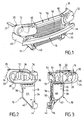
- FIG 1 represents a front face of a motor vehicle which comprises two side portions 10 each incorporating a projector housing 12 so as to constitute each time a one-piece assembly.
- These two lateral parts 10 are joined together by an upper beam 14, also called upper cross member, extending horizontally when the front-end module is mounted on a motor vehicle.
- these two lateral parts 10 are joined together by a bumper beam 16.
- one of the lateral parts 10 of the front face of the figure 1 is the side part 10 which is located on the right side of the vehicle, so on the left side of the vehicle. figure 1 .
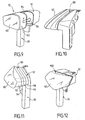
- the lateral part 10 ( Figures 2 and 3 ) is a one-piece assembly that can be achieved by any known transformation method, using a compression or injection technique.
- each of the lateral parts is advantageously made of a plastic material chosen from thermosetting materials and thermoplastics.
- a plastic material chosen from thermosetting materials and thermoplastics.
- the lateral part 10 represented in Figures 2 and 3 includes a side jamb 18 (also called jamb) which extends the projector housing 12.
- this side post 18 extends in a generally vertical direction and extends the projector housing downwardly.
- the projector housing 12 comprises a wall 20 defining a continuous curve of generally oblong shape. This wall 20 has an anterior edge 22 intended to receive a projector mirror (no shown) and a rear edge 24 facing the rear of the projector housing 12.
- the projector housing is divided by a generally vertical partition 26 in two parts: a main portion 28 for accommodating the main lamp of the projector projector and its associated reflector, and a secondary portion 30 for housing another lamp, for example that of a flashing and its associated reflector.
- the ribs 32 are arranged in the upper part of the projector housing 12 and they extend in a substantially horizontal position when the front face is located on the vehicle. These ribs 32 serve to reinforce the lateral part 10, and more particularly the casing 12, at the place where the lateral part replaces the upper beam of a conventional front face.
- the wall 20 defines, in the upper part, an interface 34 arranged to serve as attachment to one of the ends of the upper beam 14 of the figure 1 .
- This upper beam also called upper cross member, is preferably made of a plastic material of the type defined above or a hybrid material, that is to say, metal / plastic.
- Each end of the upper beam 14 is fixed on an interface 34, in the form of a housing, preferably with the aid of screws to allow its possible assembly and disassembly, for example in case of repair.
- each side portion 10 comprises a fastening tab 35, in the example attached to the projector housing 12, and intended to be fixed to an upper spar 37 of a motor vehicle.
- the lateral upright 18 is bounded by a generally vertical inner edge 36 and a generally vertical outer edge 38 which is extended by an inclined edge 40, which joins the inner edge 36 to form an end portion 42.
- the two edges 36 and 38 are sufficiently spaced from each other to provide an interface 44 for attaching the bumper beam 16 of the figure 1 .
- the attachment zones thereof, and in particular the interfaces 34 and 44 are advantageously made of metal to impart better mechanical strength. in the most stressed regions.
- the interface 44 is thus sandwiched between the bumper beam 16 and a lower beam 45 of the vehicle.
- the beam 16 comprises upper tabs 46 and lower tabs 48 for its attachment to the interface 44 by appropriate screws or bolts.
- the interfaces 44 of the lateral parts 10 are fixed directly to the bumper beam. Alternatively, they can be fixed on damping means (not shown) integrated in the bumper beam.
- Each of the lateral parts 10 thus makes a structural connection between the upper longitudinal members 37 and the lower longitudinal members 45 of the vehicle and forms part of the support of the front face. Fasteners of each side portion 10 to an upper spar and a lower spar make it possible to catch up with the dispersions of the chassis of the vehicle.
- the cross 14 is simplified compared to the state of the art, insofar as it does not directly connect the two upper longitudinal members, but only the end of the two projector housings.
- the projector housings are designed to allow, on the one hand, the transmission of the forces of the lock (fixed on the crossbar), the longitudinal members and, on the other hand, the rigid connection via the cross member of the two upper longitudinal members of the vehicle.
- the structural cross-link / housing is designed to allow a lock point adjustment, in the direction of the Y axis of the vehicle, to recover the dispersions along the X and Y axes due to the longitudinal members, to stiffen the connection between the two housings projector and thus allow the front face to withstand torsional forces, impacts, vibrations, etc.
- the inner edges 36 of the lateral portions 10 delimit, in combination with the upper beam 14, a generally rectangular space intended to receive a cooling radiator 50 ( figure 1 ) or a cooling module, that is to say an assembly comprising a cooling radiator plus possibly an air conditioning condenser and a motor-fan unit (not shown).
- Each of the lateral portions 10 comprises means for fixing the cooling module or radiator.
- these fixing means comprise fixing lugs 52, also called clips, and fasteners 54 and 56 for shock absorbing pads ( figure 3 ).
- each of the lateral portions 10 also contributes to the fixing of the radiator or cooling module 50.
- the upper beam 14 can be used to fasten a central lock through an opening 58 or two side locks through two pairs of openings 60 ( figure 1 ) which are also used for fixing the upper beam 14 on the two lateral parts 10.
- each lateral portion 10 and the upper beam 14 is designed to provide adjustment in two perpendicular directions. This allows a lock point adjustment in the direction of the Y axis of the vehicle, to recover the dispersions along the X and Y axes due to the longitudinal members, to stiffen the connection between the two projector housings 12 and thus allow the front face resist torsion, shock, vibration, etc.
- openings 60 ( figure 1 ) of the upper beam 14 are advantageously oblong openings which extend in the Y direction and which cooperate with openings 25 ( figure 7 ) of the lateral part 10.
- This embodiment of Figures 1 to 3 also offers the advantage of allowing a gain in the "Y" direction because the amount 18 is sandwiched between the bumper beam and the lower rails (not shown) of the vehicle.
- each lateral amount 18 is less wide than that of the preceding figures.
- each upright is delimited by an inner edge 62 and an outer edge 64, substantially parallel to each other, delimiting an interface 66 narrower than the interface 44 mentioned above.
- Each of the interfaces 66 comprises two holes 68 to allow the attachment of a bumper beam 16 as seen in FIGS. Figures 4 and 5 .
- the advantage of this version is that it saves space in the direction "Z", which allows for example to have a larger volume to receive an accessory, for example a can 70 ( figure 5 ) serving as an ice reservoir.
- Another advantage is to be able to use this volume available for the projector itself and thus increase its performance (larger reflector).
- the embodiment of the figure 8 is similar to that of Figures 1 to 3 , except that the side portions 10 each include a portion 72, 74, respectively, of an upper beam 14 forming a cross member and forming part of the front face. Each of the beam portions 72 and 74 is thus made in one piece with the lateral portion 10 on which it depends.
- the portion 74 includes an end piece 76 for fitting into the end 78 of the portion 72 and to be fixed by screws (not shown).
- each of the side portions 10 is sandwiched between a lower spar 45 of the vehicle and the bumper beam 16.
- FIG 9 shows a lateral portion 10 according to the invention which is arranged to damp an impact, for example a pedestrian impact, intervening on the projector.
- the projector housing 12 is closed by an ice-cream 80 which is carried by an intermediate element 82.
- This intermediate element carries the mirror 80 and is arranged to slide in the projector housing 12 and allow the ice to fall towards the rear of the vehicle in case of impact, as shown by the arrow F.
- This intermediate element 82 is in the form of a riser and is provided with a peripheral seal 84 for sealing between the riser and the projector housing.
- the element 82 is slidable inside the housing 12 without coming into contact with the reflector 86 which is placed at the bottom of the housing.
- this intermediate element can be reversible.
- the intermediate element 82 carrying the ice can be returned to its original position.
- This intermediate element is arranged to provide resistance to movement and thus to absorb some of the energy of an impact.
- this intermediate element can be retained by abutment means sufficiently strong to allow the sliding of the intermediate element as soon as the impact exceeds a sufficient level.
- an energy absorbing intermediate element 88 is also interposed between the housing 12 and the ice 80.
- it is a deformable element, in particular a bellows. This can be made of a rigid or semi-rigid material.
- This intermediate element is advantageously displaceably reversible. This means that this intermediate element will return to its original position as soon as the causes of the impact have ceased.
- the intermediate element 90 is a fuse element arranged to break at least partially in the event of an impact against the ice 80.
- the element 90 is integrated in the housing 12.
- This intermediate element is advantageously constituted by a succession of stages 92, 94, 96 and 98 interconnected by material bridges (not visible in the drawing) likely to break in case of impact. It is obvious that this intermediate element 90 is not reversibly deformable. "The assembly must therefore be replaced in case of damage during an impact.
- an intermediate fuse element 100 is also interposed between the mirror 80 and the housing 12 of the projector.
- the intermediate element 100 is integrated with the ice 80.
- the ice and the fusible intermediate element 100 are made in one piece by molding a suitable mineral or organic glass.
- the fusible intermediate element 100 comprises zones of lesser resistance, for example folds, which may rupture in a preferred manner in the event of an impact.
- the intermediate element 82, 84, 90 or 100 allows a movement of the ice 80 relative to the housing 12 and an energy absorption of an impact on the ice.
- the impact energy is absorbed and the projector no longer has a critical point or hard point on impact.
- the safety of the front panel is significantly improved.
- a lower beam which is housed under the radiator or cooling module and can serve in particular as a pedestrian beam, a converging beam, a deflector, a aerodynamic beam or acoustic insulation.
- the figure 13 shows a front of a motor vehicle that is similar to that of the figure 1 and which further comprises a lower beam 102.
- the beam 102 is a pedestrian beam intended to absorb a shock in the lower part, for example in the event of collision with a pedestrian.
- This beam 102 has two lugs 104 allowing it to be attached to the lower ends of the lateral parts 10.
Landscapes
- Engineering & Computer Science (AREA)
- Mechanical Engineering (AREA)
- Combustion & Propulsion (AREA)
- Transportation (AREA)
- Chemical & Material Sciences (AREA)
- Structural Engineering (AREA)
- Architecture (AREA)
- Body Structure For Vehicles (AREA)
- Arrangement Or Mounting Of Propulsion Units For Vehicles (AREA)
- Automatic Cycles, And Cycles In General (AREA)
- Vehicle Interior And Exterior Ornaments, Soundproofing, And Insulation (AREA)
- Window Of Vehicle (AREA)
- Lighting Device Outwards From Vehicle And Optical Signal (AREA)
- Manufacture Of Motors, Generators (AREA)
- Motor Or Generator Frames (AREA)
Claims (29)
- Vorderseite eines Kraftfahrzeugs des Typs, die einen Träger aufweist, der zwei Seitenteile (10) hat, die jeweils ein Scheinwerfergehäuse (12) derart enthalten, dass jedes Mal eine einstückige Einheit gebildet wird, dadurch gekennzeichnet, dass die Seitenteile (10) eingerichtet sind, um eine Strukturverbindung zwischen oberen Längsbalken (37) und unteren Längsbalken (45) des Fahrzeugs herzustellen, und dass jeder der Seitenteile (10) einen seitlichen Ständer oder Pfosten (18) aufweist, der das Scheinwerfergehäuse (12) verlängert.
- Vorderseite nach Anspruch 1, dadurch gekennzeichnet, dass sich jeder Seitenständer (18) entlang einer allgemein vertikalen Richtung erstreckt und das Scheinwerfergehäuse (12) nach unten verlängert.
- Vorderseite nach einem der vorhergehenden Ansprüche, dadurch gekennzeichnet, dass die Seitenteile (10) jeweilige Schnittstellen (34) haben, die jeweils zum Befestigen der Enden eines oberen Balkens (14) dienen, der einen Querbalken bildet und zur Vorderseite gehört.
- Vorderseite nach einem der vorhergehenden Ansprüche, dadurch gekennzeichnet, dass die Seitenteile (10) jeweils mit oberen Rippen (32) versehen sind.
- Vorderseite nach dem vorhergehenden Anspruch,
dadurch gekennzeichnet, dass die oberen Rippen (32) insbesondere zum Verstärken des Seitenteils (10) und insbesondere des Scheinwerfergehäuses (12), in einem Bereich dienen, in dem der Seitenteil den oberen Balken einer herkömmlichen Vorderseite ersetzt. - Vorderseite nach einem der Ansprüche 1 bis 2, dadurch gekennzeichnet, dass die Seitenteile (10) jeweils einen Teil (72, 74) eines oberen Balkens (14) integrieren, der einen Querbalken bildet und zu der Vorderseite derart gehört, dass eine einstückige Einheit gebildet wird.
- Vorderseite nach einem der Ansprüche 3 bis 6, dadurch gekennzeichnet, dass der obere Balken (14) mindestens eine Schlossbefestigung (58, 60) aufweist.
- Vorderseite nach einem der vorhergehenden Ansprüche, dadurch gekennzeichnet, dass die Seitenteile (10) jeweilige Schnittstellen (44; 66) haben, die jeweils zum Befestigen eines Stoßfängerbalkens (16) entweder direkt oder über in den Stoßfängerbalken eingebaute Dämpfmittel dienen.
- Vorderseite nach dem vorhergehenden Anspruch, dadurch gekennzeichnet, dass jeder Seitenteil (10) zwischen einem unteren Längsbalken (45) des Fahrzeugs und dem Stoßfängerbalken (16) sandwichartig eingeschlossen ist.
- Vorderseite nach Anspruch 8, dadurch gekennzeichnet, dass jeder Seitenteil (10) an dem Stoßfängerbalken (16) befestigt ist, während dieser Stoßfängerbalken an unteren Längsbalken (45) des Fahrzeugs befestigt ist.
- Vorderseite nach einem der vorhergehenden Ansprüche, dadurch gekennzeichnet, dass die Seitenteile (10) durch einen unteren Balken (102) vereint sind.
- Vorderseite nach dem vorhergehenden Anspruch, dadurch gekennzeichnet, dass der untere Balken (102) insbesondere als Fußgängerbalken, Einlauf, aerodynamischer Ablenker oder Schallisolierer dient.
- Vorderseite nach einem der vorhergehenden Ansprüche, dadurch gekennzeichnet, dass die Seitenteile (10) Befestigungsmittel für die Montage eines Kühlers oder eines Kühlmoduls (50) aufweisen.
- Vorderseite nach dem vorhergehenden Anspruch,
dadurch gekennzeichnet, dass die Befestigungsmittel des Kühlers oder des Kühlmoduls Befestigungspratzen (52) aufweisen. - Vorderseite nach einem der Ansprüche 13 und 14,
dadurch gekennzeichnet, dass die Befestigungsmittel des Kühlers oder des Kühlmoduls Befestigungen (54) für Dämpfklötze (56) aufweisen. - Vorderseite nach einem der vorhergehenden Ansprüche, dadurch gekennzeichnet, dass die Seitenteile (10) jeweils aus einem Kunststoff, der aus den Duroplast- und den Thermoplastmaterialien ausgewählt ist, ausgebildet sind.
- Vorderseite nach dem vorhergehenden Anspruch, dadurch gekennzeichnet, dass der Kunststoff aus einem Polyamid oder einem mit Glasfasern verstärkten Polypropylen ausgewählt ist.
- Vorderseite nach einem der Ansprüche 1 bis 15, dadurch gekennzeichnet, dass die Seitenteile (10) jeweils aus einem Verbund- oder Hybridmaterial des Typs Metall/Kunststoff ausgebildet sind.
- Vorderseite nach dem vorhergehenden Anspruch, dadurch gekennzeichnet, dass die Seitenteile (10) ein Metall, insbesondere in den Befestigungszonen (44, 66, 34) aufweisen.
- Vorderseite nach einem der vorhergehenden Ansprüche, bei der jedes Scheinwerfergehäuse (12) durch eine Scheibe (80) verschlossen ist, dadurch gekennzeichnet, dass ein Zwischenelement (82; 88; 90; 100) mit Energieabsorption zwischen das Scheinwerfergehäuse (12) und die Scheibe (80) eingefügt ist, um die Energie eines eventuellen Aufpralls gegen die Scheibe des Scheinwerfers zu absorbieren.
- Vorderseite nach dem vorhergehenden Anspruch, dadurch gekennzeichnet, dass das Zwischenelement (82) eingerichtet ist, um ein Bewegen der Scheibe (80) bei einem Aufprall zu erlauben.
- Vorderseite nach einem der Ansprüche 20 und 21, dadurch gekennzeichnet, dass das Zwischenelement (82) die Scheibe (80) trägt und eingerichtet ist, um in dem Scheinwerfergehäuse (12) zu gleiten und ein Zurückfahren der Scheibe zur Rückseite des Fahrzeugs bei einem Aufprall zu erlauben.
- Vorderseite nach dem vorhergehenden Anspruch, dadurch gekennzeichnet, dass das gleitende Zwischenelement (82) in Form eines Aufsatzes ausgeführt und mit einer umfänglichen Dichtung (84) versehen ist, um die Abdichtung zwischen dem Aufsatz und dem Scheinwerfergehäuse (12) sicherzustellen.
- Vorderseite nach einem der Ansprüche 20 und 21, dadurch gekennzeichnet, dass das Zwischenelement (88) in Form eines verformbaren Elements hergestellt ist, insbesondere eines Balgs, der zwischen das Scheinwerfergehäuse (12) und die Scheibe (80) eingefügt ist.
- Vorderseite nach einem der Ansprüche 20 bis 24, dadurch gekennzeichnet, dass das Zwischenelement (82; 88; 90; 100) eingerichtet ist, um einen Widerstand gegen die Bewegung zu bieten und es daher zu erlauben, einen Teil der Energie eines Aufpralls zu absorbieren.
- Vorderseite nach einem der Ansprüche 20 bis 25, dadurch gekennzeichnet, dass das Zwischenelement (82; 88) verschiebbar oder rückgängig machbar verformbar ist.
- Vorderseite nach einem der Ansprüche 20 und 21, dadurch gekennzeichnet, dass das Zwischenelement (90; 100) in Form eines Sicherungselements ausgebildet ist, das eingerichtet ist, um bei einem Aufprall gegen die Scheibe (80) zumindest zum Teil zu brechen.
- Vorderseite nach Anspruch 27, dadurch gekennzeichnet, dass das Sicherungszwischenelement .(90) in das Scheinwerfergehäuse (12) eingebaut ist.
- Vorderseite nach Anspruch 27, dadurch gekennzeichnet, dass das Sicherungszwischenelement (100) in die Scheibe (80) eingebaut ist.
Applications Claiming Priority (3)
| Application Number | Priority Date | Filing Date | Title |
|---|---|---|---|
| FR0108034 | 2001-06-19 | ||
| FR0108034A FR2825964B1 (fr) | 2001-06-19 | 2001-06-19 | Face avant de vehicule automobile avec equipements integres |
| PCT/FR2002/002089 WO2002102645A1 (fr) | 2001-06-19 | 2002-06-18 | Face avant de vehicule automobile avec equipements integres |
Publications (2)
| Publication Number | Publication Date |
|---|---|
| EP1397284A1 EP1397284A1 (de) | 2004-03-17 |
| EP1397284B1 true EP1397284B1 (de) | 2008-08-13 |
Family
ID=8864498
Family Applications (1)
| Application Number | Title | Priority Date | Filing Date |
|---|---|---|---|
| EP02751259A Expired - Lifetime EP1397284B1 (de) | 2001-06-19 | 2002-06-18 | Kraftfahrzeugvorderbau mit integrierten ausrüstungsteilen |
Country Status (6)
| Country | Link |
|---|---|
| EP (1) | EP1397284B1 (de) |
| AT (1) | ATE404418T1 (de) |
| BR (1) | BR0210571B1 (de) |
| DE (1) | DE60228248D1 (de) |
| FR (1) | FR2825964B1 (de) |
| WO (1) | WO2002102645A1 (de) |
Cited By (3)
| Publication number | Priority date | Publication date | Assignee | Title |
|---|---|---|---|---|
| DE102008059611A1 (de) * | 2008-11-28 | 2010-06-02 | Audi Ag | Scheinwerfer für Kraftfahrzeuge |
| RU2478512C2 (ru) * | 2008-09-19 | 2013-04-10 | Фольксваген Акциенгезелльшафт | Передок транспортного средства, в частности автомобиля |
| CN103946103A (zh) * | 2011-07-26 | 2014-07-23 | 法雷奥热系统公司 | 用于机动车辆的前端模块 |
Families Citing this family (12)
| Publication number | Priority date | Publication date | Assignee | Title |
|---|---|---|---|---|
| DE10314091A1 (de) * | 2003-03-28 | 2004-10-14 | Adam Opel Ag | Scheinwerfergehäuse und Fahrzeugkarosserie mit einer Aufnahme hierfür |
| DE10357920B4 (de) * | 2003-12-11 | 2009-07-09 | Daimler Ag | Fahrzeug-Beleuchtungseinrichtung |
| DE102004001703B4 (de) * | 2004-01-13 | 2009-01-02 | Adam Opel Ag | Vorderbau für ein Kraftfahrzeug |
| FR2884777A1 (fr) * | 2005-04-25 | 2006-10-27 | Renault Sas | Projecteur de vehicule automobile, procede de montage d'un tel projecteur et vehicule correspondant |
| FR2887197B1 (fr) * | 2005-06-21 | 2007-09-07 | Peugeot Citroen Automobiles Sa | Projecteur de vehicule automobile comportant une glace adapt ee pour se rompre en cas de choc |
| FR2903050B1 (fr) * | 2006-06-30 | 2009-02-27 | Valeo Systemes Thermiques | Dispositif d'eclairage ou de signalisation pour face avant de vehicule automobile et face avant comportant un tel dispositif |
| DE102008026335A1 (de) * | 2008-05-31 | 2009-12-03 | Dr. Ing. H.C. F. Porsche Aktiengesellschaft | Frontstruktur einer Fahrzeugkarosserie mit Fußgängeraufprallschutz |
| DE102009030087B4 (de) * | 2009-06-24 | 2014-11-20 | Audi Ag | Scheinwerfer für ein Fahrzeug |
| JP5629612B2 (ja) * | 2011-03-02 | 2014-11-26 | 本田技研工業株式会社 | 車両前部 |
| US8746783B2 (en) * | 2012-08-31 | 2014-06-10 | GM Global Technology Operations LLC | Positioning and reinforcement structure for a vehicle |
| DE102014224433A1 (de) * | 2014-11-28 | 2016-06-02 | Bayerische Motoren Werke Aktiengesellschaft | Frontend für ein Kraftfahrzeug |
| DE102018222621A1 (de) * | 2018-12-20 | 2020-06-25 | Volkswagen Aktiengesellschaft | Anordnung aus einem Stützelement und einem Montageträger und Verfahren zur Herstellung der Anordnung |
Family Cites Families (11)
| Publication number | Priority date | Publication date | Assignee | Title |
|---|---|---|---|---|
| FR2711958B1 (fr) * | 1993-11-05 | 1996-01-05 | Ecia Equip Composants Ind Auto | Façade avant perfectionnée pour véhicule à moteur thermique. |
| FR2713579B1 (fr) | 1993-12-15 | 1996-03-01 | Ecia Equip Composants Ind Auto | Bâti-support pour façade de véhicule automobile. |
| DE19732301B4 (de) * | 1996-08-22 | 2007-12-13 | Volkswagen Ag | Scheinwerferanordnung für ein Kraftfahrzeug |
| WO1999054187A1 (en) * | 1998-04-21 | 1999-10-28 | Textron Automotive Uk | Vehicle module |
| DE19926346A1 (de) * | 1999-06-09 | 2000-12-14 | Hella Kg Hueck & Co | Scheinwerfer |
| US6634702B1 (en) * | 1999-06-23 | 2003-10-21 | Dynamit Nobel Kunstsoff Gmbh | Front-end module for a motor vehicle |
| FR2800030B1 (fr) * | 1999-10-25 | 2002-01-11 | Plastic Omnium Cie | Piece de structure de vehicule automobile, notamment face avant technique |
| FR2801027A1 (fr) * | 1999-11-15 | 2001-05-18 | Plastic Omnium Cie | Face avant technique automobile sans radiateur |
| FR2802496B1 (fr) * | 1999-12-20 | 2002-03-01 | Valeo Thermique Moteur Sa | Procede de realisation d'une facade avant de vehicule |
| US20020015310A1 (en) * | 2000-02-23 | 2002-02-07 | Pickholz Michael F. | Vehicle structural assembly with integrally formed lamp housing |
| FR2817820B1 (fr) * | 2000-12-07 | 2003-06-06 | Plastic Omnium Cie | Piece de carrosserie de vehicule automobile munie d'un dispositif optique |
-
2001
- 2001-06-19 FR FR0108034A patent/FR2825964B1/fr not_active Expired - Lifetime
-
2002
- 2002-06-18 DE DE60228248T patent/DE60228248D1/de not_active Expired - Lifetime
- 2002-06-18 BR BRPI0210571-3A patent/BR0210571B1/pt not_active IP Right Cessation
- 2002-06-18 AT AT02751259T patent/ATE404418T1/de not_active IP Right Cessation
- 2002-06-18 WO PCT/FR2002/002089 patent/WO2002102645A1/fr active IP Right Grant
- 2002-06-18 EP EP02751259A patent/EP1397284B1/de not_active Expired - Lifetime
Cited By (4)
| Publication number | Priority date | Publication date | Assignee | Title |
|---|---|---|---|---|
| RU2478512C2 (ru) * | 2008-09-19 | 2013-04-10 | Фольксваген Акциенгезелльшафт | Передок транспортного средства, в частности автомобиля |
| DE102008059611A1 (de) * | 2008-11-28 | 2010-06-02 | Audi Ag | Scheinwerfer für Kraftfahrzeuge |
| CN103946103A (zh) * | 2011-07-26 | 2014-07-23 | 法雷奥热系统公司 | 用于机动车辆的前端模块 |
| CN103946103B (zh) * | 2011-07-26 | 2017-06-20 | 法雷奥热系统公司 | 用于机动车辆的前端模块 |
Also Published As
| Publication number | Publication date |
|---|---|
| EP1397284A1 (de) | 2004-03-17 |
| ATE404418T1 (de) | 2008-08-15 |
| FR2825964A1 (fr) | 2002-12-20 |
| DE60228248D1 (de) | 2008-09-25 |
| FR2825964B1 (fr) | 2003-12-12 |
| WO2002102645A1 (fr) | 2002-12-27 |
| BR0210571B1 (pt) | 2011-05-31 |
| BR0210571A (pt) | 2004-08-03 |
Similar Documents
| Publication | Publication Date | Title |
|---|---|---|
| EP1397284B1 (de) | Kraftfahrzeugvorderbau mit integrierten ausrüstungsteilen | |
| EP3003761B1 (de) | Teleskopisch deformierbare luftführung für einen motorkühler eines kraftfahrzeugs und damit ausgestattetes fahrzeug | |
| EP2125442B1 (de) | Aufprallsabsorptionsmodule für kraftfahrzeug | |
| EP2173602B1 (de) | Vorderfläche eines automobils mit querstange an den hauptschienen | |
| EP1963139A2 (de) | Energieaufnahmesystem für ein motorfahrzeug | |
| FR2887211A1 (fr) | Voie basse guidee pour avant de vehicule automobile | |
| EP2173601A2 (de) | Vorderfläche für ein automobil mit einem festen balken zwischen den stossdämpfern und den hauptschienen | |
| EP2125440B1 (de) | Schockabsorptionsmodul für fahrzeug | |
| EP1616753B1 (de) | Beleuchtungseinrichtung für Kraftfahrzeuge mit erhöhter Sicherheit bei einem Aufprall | |
| EP2282915A1 (de) | Stossdämpfer und fahrzeugvorbau damit | |
| FR2845060A1 (fr) | Piece d'extremite pour capot moteur d'un vehicule | |
| EP1456075A1 (de) | Kraftfahrzeug-vorderende mit einem fluidbehälter | |
| FR2842152A1 (fr) | Armature de pare-chocs avec elements absorbeur de chocs perfectionne | |
| WO2009019372A1 (fr) | Face avant de véhicule automobile | |
| EP2125441B1 (de) | Schockabsorptionsmodul für fahrzeug | |
| FR2837762A1 (fr) | Poutre pare-chocs avec absorbeur d'energie pour vehicule automobile | |
| EP1651503B1 (de) | Verformbarer längsträger für ein kraftfahrzeug | |
| EP1335849B1 (de) | Vorderfront eines kraftfahrzeuges mit einer stosstange | |
| EP1577160B1 (de) | Vorrichtung zur Befestigung einer optischen Einheit mit Stossfängern für einen Fussgängeraufprall | |
| FR2908716A1 (fr) | Dispositif de protection pour vehicule automobile et module de face avant muni d'un tel dispositif | |
| FR2833559A1 (fr) | Face avant de vehicule automobile a accessibilite amelioree | |
| EP3372478B1 (de) | Frontpaneilenteil eines kraftfahrzeugs in einem schockbereich integriert in ein starres gehäuse | |
| EP1914126B1 (de) | Frontseite eines Kraftfahrzeuges umfassend einen Energieabsorber | |
| FR2903050A1 (fr) | Dispositif d'eclairage ou de signalisation pour face avant de vehicule automobile et face avant comportant un tel dispositif |
Legal Events
| Date | Code | Title | Description |
|---|---|---|---|
| PUAI | Public reference made under article 153(3) epc to a published international application that has entered the european phase |
Free format text: ORIGINAL CODE: 0009012 |
|
| 17P | Request for examination filed |
Effective date: 20031201 |
|
| AK | Designated contracting states |
Kind code of ref document: A1 Designated state(s): AT BE CH CY DE DK ES FI FR GB GR IE IT LI LU MC NL PT SE TR |
|
| AX | Request for extension of the european patent |
Extension state: AL LT LV MK RO SI |
|
| RIN1 | Information on inventor provided before grant (corrected) |
Inventor name: GUYOMARD, JEAN-NICOLAS Inventor name: HARAND, PASCAL Inventor name: GUINEHUT, SEBASTIEN |
|
| R17C | First examination report despatched (corrected) |
Effective date: 20070112 |
|
| RAP1 | Party data changed (applicant data changed or rights of an application transferred) |
Owner name: VALEO SYSTEMES THERMIQUES |
|
| GRAP | Despatch of communication of intention to grant a patent |
Free format text: ORIGINAL CODE: EPIDOSNIGR1 |
|
| GRAS | Grant fee paid |
Free format text: ORIGINAL CODE: EPIDOSNIGR3 |
|
| GRAA | (expected) grant |
Free format text: ORIGINAL CODE: 0009210 |
|
| AK | Designated contracting states |
Kind code of ref document: B1 Designated state(s): AT BE CH CY DE DK ES FI FR GB GR IE IT LI LU MC NL PT SE TR |
|
| REG | Reference to a national code |
Ref country code: GB Ref legal event code: FG4D Free format text: NOT ENGLISH |
|
| REG | Reference to a national code |
Ref country code: CH Ref legal event code: EP |
|
| REG | Reference to a national code |
Ref country code: IE Ref legal event code: FG4D Free format text: LANGUAGE OF EP DOCUMENT: FRENCH |
|
| REF | Corresponds to: |
Ref document number: 60228248 Country of ref document: DE Date of ref document: 20080925 Kind code of ref document: P |
|
| PG25 | Lapsed in a contracting state [announced via postgrant information from national office to epo] |
Ref country code: NL Free format text: LAPSE BECAUSE OF FAILURE TO SUBMIT A TRANSLATION OF THE DESCRIPTION OR TO PAY THE FEE WITHIN THE PRESCRIBED TIME-LIMIT Effective date: 20080813 Ref country code: ES Free format text: LAPSE BECAUSE OF FAILURE TO SUBMIT A TRANSLATION OF THE DESCRIPTION OR TO PAY THE FEE WITHIN THE PRESCRIBED TIME-LIMIT Effective date: 20081124 |
|
| PG25 | Lapsed in a contracting state [announced via postgrant information from national office to epo] |
Ref country code: FI Free format text: LAPSE BECAUSE OF FAILURE TO SUBMIT A TRANSLATION OF THE DESCRIPTION OR TO PAY THE FEE WITHIN THE PRESCRIBED TIME-LIMIT Effective date: 20080813 Ref country code: AT Free format text: LAPSE BECAUSE OF FAILURE TO SUBMIT A TRANSLATION OF THE DESCRIPTION OR TO PAY THE FEE WITHIN THE PRESCRIBED TIME-LIMIT Effective date: 20080813 |
|
| REG | Reference to a national code |
Ref country code: IE Ref legal event code: FD4D |
|
| PG25 | Lapsed in a contracting state [announced via postgrant information from national office to epo] |
Ref country code: IE Free format text: LAPSE BECAUSE OF FAILURE TO SUBMIT A TRANSLATION OF THE DESCRIPTION OR TO PAY THE FEE WITHIN THE PRESCRIBED TIME-LIMIT Effective date: 20080813 Ref country code: DK Free format text: LAPSE BECAUSE OF FAILURE TO SUBMIT A TRANSLATION OF THE DESCRIPTION OR TO PAY THE FEE WITHIN THE PRESCRIBED TIME-LIMIT Effective date: 20080813 |
|
| PG25 | Lapsed in a contracting state [announced via postgrant information from national office to epo] |
Ref country code: PT Free format text: LAPSE BECAUSE OF FAILURE TO SUBMIT A TRANSLATION OF THE DESCRIPTION OR TO PAY THE FEE WITHIN THE PRESCRIBED TIME-LIMIT Effective date: 20090113 |
|
| PLBE | No opposition filed within time limit |
Free format text: ORIGINAL CODE: 0009261 |
|
| STAA | Information on the status of an ep patent application or granted ep patent |
Free format text: STATUS: NO OPPOSITION FILED WITHIN TIME LIMIT |
|
| 26N | No opposition filed |
Effective date: 20090514 |
|
| PG25 | Lapsed in a contracting state [announced via postgrant information from national office to epo] |
Ref country code: IT Free format text: LAPSE BECAUSE OF FAILURE TO SUBMIT A TRANSLATION OF THE DESCRIPTION OR TO PAY THE FEE WITHIN THE PRESCRIBED TIME-LIMIT Effective date: 20080813 |
|
| BERE | Be: lapsed |
Owner name: VALEO SYSTEMES THERMIQUES Effective date: 20090630 |
|
| PG25 | Lapsed in a contracting state [announced via postgrant information from national office to epo] |
Ref country code: SE Free format text: LAPSE BECAUSE OF FAILURE TO SUBMIT A TRANSLATION OF THE DESCRIPTION OR TO PAY THE FEE WITHIN THE PRESCRIBED TIME-LIMIT Effective date: 20081113 Ref country code: MC Free format text: LAPSE BECAUSE OF NON-PAYMENT OF DUE FEES Effective date: 20090630 |
|
| REG | Reference to a national code |
Ref country code: CH Ref legal event code: PL |
|
| GBPC | Gb: european patent ceased through non-payment of renewal fee |
Effective date: 20090618 |
|
| PG25 | Lapsed in a contracting state [announced via postgrant information from national office to epo] |
Ref country code: CH Free format text: LAPSE BECAUSE OF NON-PAYMENT OF DUE FEES Effective date: 20090630 Ref country code: LI Free format text: LAPSE BECAUSE OF NON-PAYMENT OF DUE FEES Effective date: 20090630 |
|
| PG25 | Lapsed in a contracting state [announced via postgrant information from national office to epo] |
Ref country code: GB Free format text: LAPSE BECAUSE OF NON-PAYMENT OF DUE FEES Effective date: 20090618 |
|
| PG25 | Lapsed in a contracting state [announced via postgrant information from national office to epo] |
Ref country code: BE Free format text: LAPSE BECAUSE OF NON-PAYMENT OF DUE FEES Effective date: 20090630 |
|
| PG25 | Lapsed in a contracting state [announced via postgrant information from national office to epo] |
Ref country code: GR Free format text: LAPSE BECAUSE OF FAILURE TO SUBMIT A TRANSLATION OF THE DESCRIPTION OR TO PAY THE FEE WITHIN THE PRESCRIBED TIME-LIMIT Effective date: 20081114 |
|
| PG25 | Lapsed in a contracting state [announced via postgrant information from national office to epo] |
Ref country code: LU Free format text: LAPSE BECAUSE OF NON-PAYMENT OF DUE FEES Effective date: 20090618 |
|
| PG25 | Lapsed in a contracting state [announced via postgrant information from national office to epo] |
Ref country code: TR Free format text: LAPSE BECAUSE OF FAILURE TO SUBMIT A TRANSLATION OF THE DESCRIPTION OR TO PAY THE FEE WITHIN THE PRESCRIBED TIME-LIMIT Effective date: 20080813 |
|
| PG25 | Lapsed in a contracting state [announced via postgrant information from national office to epo] |
Ref country code: CY Free format text: LAPSE BECAUSE OF FAILURE TO SUBMIT A TRANSLATION OF THE DESCRIPTION OR TO PAY THE FEE WITHIN THE PRESCRIBED TIME-LIMIT Effective date: 20080813 |
|
| REG | Reference to a national code |
Ref country code: FR Ref legal event code: PLFP Year of fee payment: 15 |
|
| REG | Reference to a national code |
Ref country code: FR Ref legal event code: PLFP Year of fee payment: 16 |
|
| REG | Reference to a national code |
Ref country code: FR Ref legal event code: PLFP Year of fee payment: 17 |
|
| PGFP | Annual fee paid to national office [announced via postgrant information from national office to epo] |
Ref country code: DE Payment date: 20200612 Year of fee payment: 19 Ref country code: FR Payment date: 20200630 Year of fee payment: 19 |
|
| REG | Reference to a national code |
Ref country code: DE Ref legal event code: R119 Ref document number: 60228248 Country of ref document: DE |
|
| PG25 | Lapsed in a contracting state [announced via postgrant information from national office to epo] |
Ref country code: DE Free format text: LAPSE BECAUSE OF NON-PAYMENT OF DUE FEES Effective date: 20220101 |
|
| PG25 | Lapsed in a contracting state [announced via postgrant information from national office to epo] |
Ref country code: FR Free format text: LAPSE BECAUSE OF NON-PAYMENT OF DUE FEES Effective date: 20210630 |