EP1396743B1 - Fibre optique à compensation de dispersion - Google Patents
Fibre optique à compensation de dispersion Download PDFInfo
- Publication number
- EP1396743B1 EP1396743B1 EP03010402A EP03010402A EP1396743B1 EP 1396743 B1 EP1396743 B1 EP 1396743B1 EP 03010402 A EP03010402 A EP 03010402A EP 03010402 A EP03010402 A EP 03010402A EP 1396743 B1 EP1396743 B1 EP 1396743B1
- Authority
- EP
- European Patent Office
- Prior art keywords
- region
- approximately
- optical fiber
- fiber
- dispersion
- Prior art date
- Legal status (The legal status is an assumption and is not a legal conclusion. Google has not performed a legal analysis and makes no representation as to the accuracy of the status listed.)
- Expired - Lifetime
Links
Images


Classifications
-
- G—PHYSICS
- G02—OPTICS
- G02B—OPTICAL ELEMENTS, SYSTEMS OR APPARATUS
- G02B6/00—Light guides; Structural details of arrangements comprising light guides and other optical elements, e.g. couplings
- G02B6/02—Optical fibres with cladding with or without a coating
- G02B6/02004—Optical fibres with cladding with or without a coating characterised by the core effective area or mode field radius
- G02B6/02009—Large effective area or mode field radius, e.g. to reduce nonlinear effects in single mode fibres
-
- G—PHYSICS
- G02—OPTICS
- G02B—OPTICAL ELEMENTS, SYSTEMS OR APPARATUS
- G02B6/00—Light guides; Structural details of arrangements comprising light guides and other optical elements, e.g. couplings
- G02B6/02—Optical fibres with cladding with or without a coating
- G02B6/02214—Optical fibres with cladding with or without a coating tailored to obtain the desired dispersion, e.g. dispersion shifted, dispersion flattened
- G02B6/02219—Characterised by the wavelength dispersion properties in the silica low loss window around 1550 nm, i.e. S, C, L and U bands from 1460-1675 nm
- G02B6/02252—Negative dispersion fibres at 1550 nm
- G02B6/02261—Dispersion compensating fibres, i.e. for compensating positive dispersion of other fibres
-
- G—PHYSICS
- G02—OPTICS
- G02B—OPTICAL ELEMENTS, SYSTEMS OR APPARATUS
- G02B6/00—Light guides; Structural details of arrangements comprising light guides and other optical elements, e.g. couplings
- G02B6/02—Optical fibres with cladding with or without a coating
- G02B6/036—Optical fibres with cladding with or without a coating core or cladding comprising multiple layers
- G02B6/03616—Optical fibres characterised both by the number of different refractive index layers around the central core segment, i.e. around the innermost high index core layer, and their relative refractive index difference
- G02B6/03661—Optical fibres characterised both by the number of different refractive index layers around the central core segment, i.e. around the innermost high index core layer, and their relative refractive index difference having 4 layers only
- G02B6/03666—Optical fibres characterised both by the number of different refractive index layers around the central core segment, i.e. around the innermost high index core layer, and their relative refractive index difference having 4 layers only arranged - + - +
-
- G—PHYSICS
- G02—OPTICS
- G02B—OPTICAL ELEMENTS, SYSTEMS OR APPARATUS
- G02B6/00—Light guides; Structural details of arrangements comprising light guides and other optical elements, e.g. couplings
- G02B6/02—Optical fibres with cladding with or without a coating
- G02B6/028—Optical fibres with cladding with or without a coating with core or cladding having graded refractive index
- G02B6/0281—Graded index region forming part of the central core segment, e.g. alpha profile, triangular, trapezoidal core
-
- G—PHYSICS
- G02—OPTICS
- G02B—OPTICAL ELEMENTS, SYSTEMS OR APPARATUS
- G02B6/00—Light guides; Structural details of arrangements comprising light guides and other optical elements, e.g. couplings
- G02B6/24—Coupling light guides
- G02B6/26—Optical coupling means
- G02B6/28—Optical coupling means having data bus means, i.e. plural waveguides interconnected and providing an inherently bidirectional system by mixing and splitting signals
- G02B6/293—Optical coupling means having data bus means, i.e. plural waveguides interconnected and providing an inherently bidirectional system by mixing and splitting signals with wavelength selective means
- G02B6/29371—Optical coupling means having data bus means, i.e. plural waveguides interconnected and providing an inherently bidirectional system by mixing and splitting signals with wavelength selective means operating principle based on material dispersion
- G02B6/29374—Optical coupling means having data bus means, i.e. plural waveguides interconnected and providing an inherently bidirectional system by mixing and splitting signals with wavelength selective means operating principle based on material dispersion in an optical light guide
- G02B6/29376—Optical coupling means having data bus means, i.e. plural waveguides interconnected and providing an inherently bidirectional system by mixing and splitting signals with wavelength selective means operating principle based on material dispersion in an optical light guide coupling light guides for controlling wavelength dispersion, e.g. by concatenation of two light guides having different dispersion properties
- G02B6/29377—Optical coupling means having data bus means, i.e. plural waveguides interconnected and providing an inherently bidirectional system by mixing and splitting signals with wavelength selective means operating principle based on material dispersion in an optical light guide coupling light guides for controlling wavelength dispersion, e.g. by concatenation of two light guides having different dispersion properties controlling dispersion around 1550 nm, i.e. S, C, L and U bands from 1460-1675 nm
Definitions
- the invention relates to an inverse dispersion optical fiber. More particularly, the invention relates to an inverse dispersion optical fiber having reduced optical loss relative to conventional inverse dispersion fiber and that is suitable for compensating dispersion in large effective area positive dispersion fiber.
- Optical fibers are thin strands of glass or plastic capable of transmitting optical signals, containing relatively large amounts of information, over long distances and with relatively low attenuation.
- optical fibers are made by heating and drawing a portion of an optical preform comprising a refractive core region surrounded by a protective cladding region made of glass or other suitable material.
- Optical fibers drawn from the preform typically are protected further by one or more coatings applied to the cladding region.
- the '516 patent discloses an optical fiber that reduces these nonlinear interactions by introducing a small amount of chromatic dispersion at the operating wavelengths.
- the optical power carried by the optical fiber also increases.
- the nonlinear effects caused by interaction between the channels also increases.
- Dispersion in a glass fiber causes pulse spreading for pulses that include a range of wavelengths, due to the fact that the speed of light in a glass fiber is a function of the transmission wavelength of the light. Pulse broadening is a function of the fiber dispersion, the fiber length and the spectral width of the light source.
- Dispersion for individual fibers is generally illustrated using a graph (not shown) having dispersion on the vertical axis (in units of picoseconds (ps) per nanometer (nm), or ps/nm) or ps/nm-km (kilometer) and wavelength on the horizontal axis.
- the vertical axis may range from, for example, - 250 to + 25 ps/nm km.
- the wavelength on the horizontal axis at which the dispersion equals zero corresponds to the highest bandwidth for the fiber. However, this wavelength typically does not coincide with the wavelength at which the fiber transmits light with minimum attenuation.
- typical single mode fibers generally transmit best (i.e., with minimum attenuation) at 1550 nm, whereas dispersion for the same fiber would be approximately zero at 1310 nm.
- dispersion for the same fiber would be approximately zero at 1310 nm.
- the aforementioned theoretical minimum loss for glass fiber occurs at the transmission wavelength of about 1550 nm. Because minimum attenuation is prioritized over zero dispersion, the wavelength normally used to transmit over such fibers is typically 1550 nm.
- Erbium-doped amplifiers which currently are the most commonly used optical amplifiers for amplifying optical signals carried on a fiber, operate in 1530 to 1565 nm range.
- dispersion for such a fiber normally will be closest to zero at a wavelength of 1310 nm rather than at the optimum transmission wavelength of 1550 nm, attempts are constantly being made to improve dispersion compensation over the transmission path in order to provide best overall system performance (i.e., low optical loss and low dispersion).
- the transmission fiber which normally is a positive dispersion fiber (PDF)
- PDF positive dispersion fiber
- IDF inverse dispersion fiber
- the positive dispersion transmission fiber typically comprises a single mode fiber designed to introduce dispersion in order to reduce the nonlinear interactions between channels.
- the inverse dispersion fiber has a negative dispersion and negative dispersion slope that match the dispersion characteristics of the positive dispersion transmission fiber (but are opposite in sign) in order to compensate dispersion in a broad wavelength range and minimize the residual dispersion (i.e., dispersion on wavelength channels other than the center wavelength channel being compensated).
- a transmission PDF is coupled to a length of 1DF by splicing.
- the combination of the PDF and the IDF has both an intrinsic fiber loss and a splicing loss.
- overall optical loss for a transmission link should be kept at a minimum. This is especially true over long transmission links because more amplifiers are needed in order to prevent transmission quality degeneration when the transmission link has larger losses.
- Conventional IDF has a median loss of, for example, approximately, 0.246 db/km at 1550 nm.
- One way to decrease the overall loss of the transmission link would be to utilize an IDF that has a lower fiber loss than the conventional IDF that is currently being used.
- the refractive index profile shows how the index of refraction of the fiber varies as a function of distance from its central axis.
- Parameters used for describing the refractive index profile generally are referenced to the index of refraction of the outermost layer of glass.
- Idealized models of refractive-index profile typically comprise axially symmetric rings or regions of different refractive index. However, changing the number, size and/or shape of any one of these regions generally impacts more than one characteristic of the fiber (e.g., dispersion slope is reduced, but bending loss is increased or effective area is decreased). Thus, it is a significant design effort to create a refractive index profile that provides most if not all of the desired features for the fiber, and yet still be readily manufacturable.
- IDF with a refractive index profile that provides the IDF with a lower fiber loss than the fiber loss of the conventional IDF currently being used and that provides minimal accumulation of residual dispersion over a transmission link comprising a combination of a PDF and an IDF.
- the loss when splicing this IDF to a PDF should be kept as low as possible.
- IDF that is suitable for compensating dispersion of a large effective area PDF, such as a super-large effective area PDF.
- EP 1 195 627 describes a low-loss inverse dispersion optical fiber having a dispersion between -18 ps/nm.km and -8ps/nm.km
- the invention is embodied in an optical communications system including one or more optical transmission devices, one or more optical receiving devices, and at least one optical fiber cable coupled therebetween that includes at least one positive dispersion optical fiber and corresponding inverse dispersion optical fiber.
- the inverse dispersion fiber has negative dispersion and a negative dispersion slope around the wavelength 1550 nm.
- the inverse dispersion fiber includes a doped core region with an index of refraction n 1 , a cladding region with an index of refraction n 2 , and a trench region, a first barrier region and a second barrier region with indices of refraction n 3 , n 4 , and n 5 , respectively, formed between the doped core region and the cladding region.
- Inverse dispersion fiber preferably has a chromatic dispersion of approximately - 44 picosecond/(nanometer-kilometer) and a relatively large effective mode-field area, A eff , e.g., greater than approximately 30.0 ⁇ m 2 , both at a wavelength of 1550 nanometers.
- the various regions of the inverse dispersion fiber are manufactured in such a way that the refractive index value ranges preferably are, e.g., 0.709% ⁇ (n 1 -n 2 )/n 2 ⁇ 1%, -0.358% ⁇ (n 3 -n 2 )/n 2 ⁇ -0.293%, 0.194% ⁇ (n 4 -n 2 )/n 2 ⁇ 0.237%, and -0.045% ⁇ (n 5 -n 2 )/n 2 ⁇ -0.037%.
- manufacture of the optical fiber includes manufacture of a core region having a diameter of approximately 4.83 ⁇ m, a trench region having a diameter of approximately 11.01 ⁇ m, a first barrier region having a diameter of approximately -18.44 ⁇ m, and a second barrier region having a diameter of approximately 21.97 ⁇ m.
- the refractive index of the core preferably is graded to follow a power law, with an exponent ofy, where 1 ⁇ ⁇ ⁇ 7.
- the core region is doped with, for example, germanium or other suitable material.
- the trench region, the first barrier region, the second barrier and the cladding region are doped with, for example, germanium and/or fluorine, and/or other suitable material(s).
- Inverse dispersion optical fiber according to embodiments of the invention provides improved compensation of positive dispersion optical fibers, including existing positive dispersion optical fibers.
- the IDF described herein will be described as having particular properties and a particular refractive index profile. However, it should be noted that the IDF described herein is an example of the IDF of the present invention. Those skilled in the art will understand, in view of the discussion provided herein, that the IDF of the present invention is not limited to any particular IDF. IDFs having properties and refractive index profiles different from those of the IDF described herein are also within the scope of the present invention.
- the IDF of the present invention is suitable for compensating dispersion in many types of optical fibers such as, for example, positive dispersion, pure silica core fiber from Sumitomo Electric Industries, Ltd., as described in "Ultra Low Nonlinearity Low Loss Pure Silica Core Fiber,” Electronics Letters Online No: 19991094, 3 August 1999, Vascade 100 fiber from Coming, large effective area fiber from Fujitsu and UltraWave® SLA fiber from Fitel USA Corporation.
- optical fibers such as, for example, positive dispersion, pure silica core fiber from Sumitomo Electric Industries, Ltd., as described in "Ultra Low Nonlinearity Low Loss Pure Silica Core Fiber," Electronics Letters Online No: 19991094, 3 August 1999, Vascade 100 fiber from Coming, large effective area fiber from Fujitsu and UltraWave® SLA fiber from Fitel USA Corporation.
- Fig. 1A shows a cross-sectional view of an IDF 10 and fig. 1B shows its corresponding refractive index profile in accordance with the preferred embodiment of the present invention.
- the IDF 10 includes a plurality of layers 11, 12, 13, 14 and 15, each of which has a different index of refraction.
- the region 11 corresponds to the central core of the optical fiber 10 and has a nominal index of refraction n 1 .
- the central core region 11 is surrounded by a first annular ring or region 12 (trench region) that has a nominal refractive index n 3 .
- the trench region 12 is surrounded by a second annular region 13 (first barrier region), which has a nominal refractive index n 4 .
- the second region 13 is surrounded by a third annular region 14 (second barrier region) that has a nominal refractive index n 5 .
- An outer cladding 15 of nominal refractive index n 2 surrounds region 14.
- the optical fiber 10 is not drawn to scale (the outer diameter of cladding layer 15 preferably is approximately 125 ⁇ m, while the diameter of the core region 11 preferably is less than approximately 6 ⁇ m).
- the first region 12 will be referred to hereinafter as a trench region
- the second region 13 will be referred to hereinafter as a first barrier region
- the third region 14 will be referred to hereinafter as a second barrier region.
- the region 15 will be referred to hereinafter as the outer cladding.
- the fiber 10 is a graded-index fiber and the refractive index changes between adjacent layers are gradual.
- abrupt changes are shown in Fig. 1A to enable distinctions between the regions to be easily made.
- Fig. 1B is a graphical representation of the refractive index profile 20 of the fiber 10 shown in Fig. 1A.
- the Y-axis corresponds to refractive index x 100 and the X-axis corresponds to positions along a radius from the center of the core 1 of the fiber 10 to the outer edge of the cladding 15 of the fiber 10.
- the refractive index values shown in Fig. 1B are actually relative refractive index values, i.e., they are relative to the refractive index of the outer cladding 15. Therefore, the index values given in Fig.
- the core region 11 has an index of refraction n 1 .
- the trench region 12 has an index of refraction n 3 , which is less than n 1 .
- the first barrier region 13 has an index of refraction n 4 , which is greater than n 3 .
- the second barrier region 14 has an index of refraction n 5 , which is less than n 4 (that of the first barrier region) but greater than n 3 (that of the trench region).
- the cladding region 15 has an index of refraction n 2 , which is greater than n 3 (that of the trench region) and n 5 (that of the second barrier region), but less than n 4 (that of the first barrier region) and n 1 (that of the core).
- the core region 11 has a radius b 1 .
- the trench region 12 has an outer radius b 2 and an inner radius is b 1 .
- the first barrier region 13 has an outer radius b 3 and an inner radius b 2 .
- the second barrier region 14 has an outer radius b 4 and an inner radius b 3 .
- the cladding region 15 has an outer radius b 5 and an inner radius b 4 .
- the fiber refractive index profile 20 shown in Fig. 1B represents a fiber in accordance with the preferred embodiment of the present invention, which comprises a germanium-doped silica (SiO 2 ) core 11 (e.g., SiO 2 doped with an appropriate amount of GeO 2 ), a fluorine (F) and/or germanium (Ge)-doped trench region 12 surrounding the core region 1 (e.g., SiO 2 doped with an appropriate amount of GeO 2 and F), a germanium and/or fluorine and/or phosphorous-doped first barrier region 13 surrounding the trench region 12 (e.g., SiO 2 doped with an appropriate amount of GeO 2 , F and P), a germanium and/or fluorine-doped and/or phosphorous-doped second barrier region 14 surrounding the first barrier region 13 (e.g., SiO 2 doped with an appropriate amount of GeO 2 and F, and P) and a pure silica outer cladding 15 surrounding the second barrier
- the nominal refractive indices n 1 , n 3 , n 4 and n 5 are all relative to the refractive index n 2 of the cladding 15, which corresponds to the X-axis in Fig. 1B.
- the nominal refractive index n 1 of the core region 11 is approximately 0.788 %.
- the nominal refractive index n 3 of the trench region 12 is approximately -0.326%.
- the nominal refractive index n 4 of the first barrier region 13 is approximately 0.215%.
- the nominal refractive index n 5 of the second barrier region 14 is approximately -0.041 %.
- the refractive index profile provides negative dispersion, inverse dispersion, or dispersion compensating optical fiber with relatively large effective transmission area (i.e., effective mode-field area, A eff ) and transmission characteristics that provide an improved dispersion and dispersion slope match with super-large effective area (SLA) positive dispersion fibers, such as those discussed previously herein.
- effective transmission area i.e., effective mode-field area, A eff
- SLA super-large effective area
- the portion of the profile 20 labeled with the refractive index of n 1 corresponds to the core region 11 of the fiber 10.
- the portion of the profile 20 labeled with the nominal refractive index of n 3 corresponds to the trench region 12 of the fiber 10.
- the portion of the profile 20 labeled with the nominal refractive index of n 4 corresponds to the first barrier region 13 of the fiber 10.
- the portion of the profile 20 labeled with the nominal refractive index of n 5 corresponds to the second barrier region 14 of the fiber 10.
- the portion of the profile 20 labeled with the nominal refractive index of n 2 corresponds to the cladding region 15 of the fiber 10.
- the core I 1 has a nominal index of refraction (n 1 ) that is positive
- the trench region 12 has an index of refraction (n 3 ) that is negative
- the first barrier region 13 has a nominal index of refraction (n 4 ) that is positive, but less than the refractive index n 1 of the core region 11. Therefore, the first barrier region 13 has a nominal index of refraction n 4 that is greater than that of the trench region n 3 .
- the second barrier region 14 has a nominal index of refraction n 5 , which is less than n 4 (that of the first barrier region) but greater than n 3 (that of the trench region).
- the cladding region 15 has an index of refraction n 2 , which is greater than n 3 (that of the trench region) and n 5 (that of the second barrier region), but less than n 4 (that of the first barrier region) and n 1 (that of the core).
- Fig. 2A is identical to Fig. 1A and is repeated to demonstrate how the refractive index differences shown in Fig. 2B correspond to the regions 11 - 15 of the optical fiber 10 of the present invention shown in Fig. 2A.
- Fig. 2B is a refractive index difference profile 30.
- the dashed lines between Fig. 2A and Fig. 2B show how the refractive index differences ⁇ 1 , ⁇ 2 , ⁇ 3 and ⁇ 4 relate to regions 11 - 15 of the fiber 10.
- the following delta values are obtained: ⁇ 1 ⁇ 0.788%; ⁇ 2 ⁇ -0.326%; ⁇ 3 ⁇ 0.215%; and ⁇ 4 ⁇ -0.041%.
- the ranges for the delta values are as follows: 0.709 % ⁇ ⁇ 1 ⁇ 1 %; -0.358 % ⁇ 2 ⁇ -0.293%; 0.194 % ⁇ 3 ⁇ % 0.237; and-0.045% ⁇ ⁇ 4 ⁇ -0.037%.
- b 1 is approximately 2.41 ⁇ m (i.e., the core region diameter is approximately 4.83 ⁇ m)
- b 2 is approximately 5.50 ⁇ m (i.e., the trench region diameter is approximately 11.01 ⁇ m)
- b 3 is approximately 9.22 ⁇ m (i.e., the first barrier region diameter is approximately 18.44 ⁇ m)
- b 4 is approximately 10.98 ⁇ m (i.e., the second barrier region diameter is approximately 21.97 ⁇ m).
- the width of the trench region is approximately 3.09 ⁇ m (5.50 ⁇ m - 2.41 ⁇ m)
- the width of the first barrier region is approximately 3.72 ⁇ m (9.22 ⁇ m - 5.50 ⁇ m)
- the width of the second barrier region is approximately 1.76 ⁇ m (10.98 ⁇ m - 9.22 ⁇ m).
- the following table shows the refractive indices for each of the regions 11 - 14 as well as the diameters of each of the regions 11 - 14 of the optical fiber of the present invention in accordance with the preferred embodiment.
- Fiber Region Diameter [micron] Refractive index (x1000) absolute index difference compared to SiO 2
- Second Barrier Region 21.97 -0.59 First Barrier Region 18.44 3.12 Trench 11.01 -4.72 Core 4.83 11.43 Index profile exponent Core ⁇ 4
- the refractive index values given in Table 1 are the absolute values as opposed to relative values.
- n ( r ) n 0 ⁇ (1-( r / r 0 ) r ) r ⁇ r 0
- n(r) is the core refractive index as a function of the fiber radius
- ⁇ the core index profile exponent
- n 0 is the maximum core refractive index and the term r 0 is the maximum core radius.
- the effect of making a core according to the refractive index profile defined by Equation 1 is to lower the anomalous fiber loss term, ⁇ anamalous , which is given by the following equation: ⁇ anomalous ⁇ ⁇ 2 ( ⁇ + 2) 2 Using a core exponent ⁇ of 4, as is the case with the preferred embodiment of the present invention, enables the anomalous loss term ⁇ anamalous to be lowered by more than a factor of 2 compared to a similar fiber that has a stepped core refractive index profile with a core exponent ⁇ of 30 or more.
- the range of ⁇ is approximately 1 ⁇ ⁇ ⁇ 7 ⁇ 7.
- RDS ( ⁇ D / ⁇ )/ D , where D is the chromatic dispersion of the fiber and the derivative of D with respect ⁇ is the chromatic dispersion slope of the fiber.
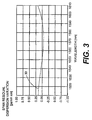
- Fig. 3 is a graph that illustrates the obtainable residual dispersion as a function of wavelength for a span of an optical fiber link comprising a length of SLA fiber and a length of the IDF fiber of the present invention. It can be seen that the residual dispersion variation can be kept very low in a broad wavelength range around 1550 nm and the curve 30 can be made zero, if desired, at the target transmission wavelength of 1550 nm.
- the Fiber 10 of the present invention has improved fiber loss characteristics compared to other IDFs, as shown below in Table 3.
- the fiber 10 of the present invention has a median loss of 0.234 decibels per kilometer (dB/km) at 1550 nm.
- the “median loss” is the loss value where 50% of the loss measurements fall below the median loss value and 50% of the loss measurements exceed the median value. This is a large improvement over other conventional IDF fibers (not shown) that have been used in the past and that generally have a median loss of at least approximately 0.246 decibels/km (dB/km) at 1550 nm.
- Table 3 shows the loss for a full 45 km span of combined UltraWave® SLA fiber and a conventional IDF fiber, for a full 45 km span of combined UltraWave® SLA fiber and the IDF fiber of the present invention and for a full 45 km span of combined, conventional non-zero-dispersion submarine fibers, one of which has a large effective area and the other of which has a low dispersion slope.
- the equivalent effective area is defined as the effective area of a non-zero dispersion shifted fiber with attenuation 0.21 dB/km, which will result in the same non-linear phase shift from self-phase modulation as the transmission span of interest.
- the launched input power is adjusted so as to keep a constant output power.
- Fiber combination Equivalent effective area Loss including splices SLA/conventional IDF 63.9 0.233 SLA/IDF in accordance with the preferred embodiment of the invention 73.3 0.218 Conventional NZDF solution 64 0.218
- Table 3 the span that utilizes the IDF of the present invention has a larger equivalent effective area and lower loss than with the other spans.
- Table 2 the chromatic dispersion of the fiber of the present invention having the index profile of Fig. 1B is - 44.16 ps/nm km at 1550 nm, which is greater (numerically) than that of typical IDFs at 1550 nm.
- the fiber 10 of the present invention allows an optical fiber link to be made that has very low residual dispersion over the transmission band while, at the same time, providing a large equivalent effective area (and thus low non-linear penalties and low optical loss in the optical fiber link).
Claims (7)
- Système de communications à fibre optique, comprenant :dans lequel la fibre optique à dispersion inverse (10) comporteau moins une source d'énergie optique ;un câble à fibre optique comportant au moins une fibre optique à dispersion positive couplée à ladite au moins une source, et au moins une fibre optique à dispersion inverse couplée à la fibre optique à dispersion positive,
une région de noyau dopée (11) ayant un indice de réfraction n1,
une région de revêtement (15) ayant un indice de réfraction n2,
une région de tranchée (12) entre la région de noyau dopée (11) et la région de revêtement (15) et adjacente à la région de noyau dopée (11), la région de tranchée (12) ayant un indice de réfraction n3,
une première région de barrière (13) entre la région de noyau dopée (11) et la région de revêtement (15) et adjacente à la région de tranchée (12), la première région de barrière (13) ayant un indice de réfraction n4, et
une deuxième région de barrière (14) entre la région de noyau dopée (11) et la région de revêtement (15) et adjacente à la première région de barrière (13), la deuxième région de barrière (14) ayant un indice de réfraction n5,
dans lequel la région de noyau dopée (11), la région de revêtement (15), la région de tranchée (12), la première région de barrière (13) et la deuxième région de barrière (14) sont configurées de sorte qu'environ 0,709% < (n1-n2)/n2 < 1%, environ -0,358% < (n3-n2)/n2 < -0,293%, environ 0,194% < (n4-n2) /n2 < 0,237%, et environ -0.045% < (n5- n2)/n2 < -0,037%, dans lequel Δ1-(n1-n2)/n2, Δ2=(n3-n2)/n2, Δ3=(n4-n2)/n2 et Δ4=(n5-n2)/n2,
dans lequel le rayon de la région de noyau dopée (11) est d'environ 2,4 µm, la largeur de la région de tranchée (12) est d'environ 3,1 µm, la largeur de la première région de barrière (13) est d'environ 3,7 µm et la largeur de la deuxième région de barrière (14) est d'environ 1,8 µm,
dans lequel la fibre optique à dispersion inverse (10) a une dispersion chromatique comprise entre environ -48 picosecondes/(nanomètre-kilomètre) et -38 picosecondes/ (nanomètre-kilomètre) à une longueur d'onde de 1550 nanomètres (nm),
dans lequel la fibre optique à dispersion inverse (10) a une perte moyenne inférieure ou égale à environ 0,235 décibels (dB) par kilomètre (dB/km) à 1550 nm ; et
au moins un récepteur couplé à la fibre optique à dispersion inverse (10) destiné à recevoir l'énergie optique de la source. - Système selon la revendication 1, dans lequel la fibre optique à dispersion inverse (10) a une pente de dispersion relative (RDS) qui est d'environ 0,0030 nm-1 à une longueur d'onde de 1550 nm.
- Système selon la revendication 1, dans lequel Δ1 est d'environ 0,788%, Δ2 est d'environ -0,326%, Δ3 est d'environ 0,215% et Δ4 est d'environ -0,041%.
- Système selon la revendication 1, dans lequel la fibre optique à dispersion inverse (10) présente une surface de champ de mode effective, Aeff, d'au moins environ 30 micromètres carrés (µm2) à une longueur d'onde de 1550 nm.
- Système selon la revendication 1, dans lequel le câble à fibre optique comprend, par ailleurs, une pluralité de fibres à dispersion inverse (10) épissées l'une à l'autre, dans lequel la perte due à l'épissure entre fibres à dispersion inverse épissées est inférieure ou égale à 0,15 dB à une longueur d'onde d'environ 1550 nm.
- Système selon la revendication 1, dans lequel la perte due à l'épissure entre la fibre à dispersion positive et ladite au moins une fibre à dispersion inverse (10) est inférieure ou égale à 0,40 dB à une longueur d'onde d'environ 1550 nm.
- Système selon la revendication 1, dans lequel la fibre optique à dispersion inverse (10) a un diamètre de champ de mode (MFD) d'environ 6,4 µm à une longueur d'onde de 1550 nm.
Applications Claiming Priority (2)
| Application Number | Priority Date | Filing Date | Title |
|---|---|---|---|
| US234818 | 1994-04-28 | ||
| US10/234,818 US6707976B1 (en) | 2002-09-04 | 2002-09-04 | Inverse dispersion compensating fiber |
Publications (3)
| Publication Number | Publication Date |
|---|---|
| EP1396743A2 EP1396743A2 (fr) | 2004-03-10 |
| EP1396743A3 EP1396743A3 (fr) | 2004-04-28 |
| EP1396743B1 true EP1396743B1 (fr) | 2005-12-21 |
Family
ID=31715290
Family Applications (1)
| Application Number | Title | Priority Date | Filing Date |
|---|---|---|---|
| EP03010402A Expired - Lifetime EP1396743B1 (fr) | 2002-09-04 | 2003-05-08 | Fibre optique à compensation de dispersion |
Country Status (4)
| Country | Link |
|---|---|
| US (1) | US6707976B1 (fr) |
| EP (1) | EP1396743B1 (fr) |
| JP (1) | JP4005960B2 (fr) |
| DE (1) | DE60302843T2 (fr) |
Families Citing this family (18)
| Publication number | Priority date | Publication date | Assignee | Title |
|---|---|---|---|---|
| US7194171B2 (en) * | 1999-07-19 | 2007-03-20 | Sumitomo Electric Industries, Ltd. | Dispersion compensating optical fiber, dispersion compensating device, optical transmission line and optical transmission system |
| US20030099450A1 (en) * | 2001-11-28 | 2003-05-29 | Huailiang Wei | Profile for limited mode fiber |
| JP2003287642A (ja) * | 2002-01-22 | 2003-10-10 | Fujikura Ltd | 光ファイバ及び光伝送路 |
| US7102812B2 (en) * | 2002-10-15 | 2006-09-05 | Corning Incorporated | Devices and methods for raman amplification and dispersion compensation |
| US6959137B2 (en) * | 2003-06-11 | 2005-10-25 | Fitel U.S.A. Corporation | Large-effective-area inverse dispersion compensating fiber, and a transmission line incorporating the same |
| US7542761B2 (en) * | 2004-10-06 | 2009-06-02 | At&T Mobility Ii Llc | Voice quality on a communication link based on customer feedback |
| FR2893149B1 (fr) * | 2005-11-10 | 2008-01-11 | Draka Comteq France | Fibre optique monomode. |
| FR2899693B1 (fr) * | 2006-04-10 | 2008-08-22 | Draka Comteq France | Fibre optique monomode. |
| US7844154B2 (en) * | 2007-05-07 | 2010-11-30 | Corning Incorporated | Optical fiber for optical power transmission |
| US8107784B2 (en) * | 2007-06-15 | 2012-01-31 | Ofs Fitel, Llc | Reduced bend sensitivity and catastrophic bend loss in single mode optical fibers and method of making same |
| DK2206001T3 (da) | 2007-11-09 | 2014-07-07 | Draka Comteq Bv | Optisk fiber, der er modstandsdygtig over for mikrobøjning |
| FR2930997B1 (fr) | 2008-05-06 | 2010-08-13 | Draka Comteq France Sa | Fibre optique monomode |
| US7570857B1 (en) | 2008-05-08 | 2009-08-04 | Corning Incorporated | Low bend loss dispersion slope compensating optical fiber |
| US7565048B1 (en) * | 2008-05-30 | 2009-07-21 | Ofs Fitel Llc | Undersea optical fiber transmission systems |
| US9075243B2 (en) * | 2011-03-01 | 2015-07-07 | Ofs Fitel, Llc | Method and system for ultrashort pulse fiber delivery using higher order mode fiber |
| US8804233B2 (en) * | 2011-08-09 | 2014-08-12 | Ofs Fitel, Llc | Fiber assembly for all-fiber delivery of high energy femtosecond pulses |
| CN105548078A (zh) * | 2016-01-13 | 2016-05-04 | 中国计量学院 | 一种基于侧边抛磨渐变折射率光纤的氢气传感装置 |
| CN110221382B (zh) * | 2019-06-12 | 2020-07-07 | 烽火通信科技股份有限公司 | 一种超低衰减大有效面积的单模光纤 |
Family Cites Families (30)
| Publication number | Priority date | Publication date | Assignee | Title |
|---|---|---|---|---|
| US4261639A (en) | 1979-11-13 | 1981-04-14 | Bell Telephone Laboratories, Incorporated | Optical pulse equalization in single-mode fibers |
| DE3586052D1 (de) | 1984-08-13 | 1992-06-17 | United Technologies Corp | Verfahren zum einlagern optischer gitter in faseroptik. |
| US5367588A (en) | 1992-10-29 | 1994-11-22 | Her Majesty The Queen In Right Of Canada, As Represented By The Minister Of Communications | Method of fabricating Bragg gratings using a silica glass phase grating mask and mask used by same |
| JP2766919B2 (ja) | 1991-06-07 | 1998-06-18 | 三菱電機株式会社 | ディジタル信号記録再生装置、ディジタル信号記録装置、ディジタル信号再生装置 |
| US5191631A (en) | 1991-12-19 | 1993-03-02 | At&T Bell Laboratories | Hybrid optical fiber and method of increasing the effective area of optical transmission using same |
| US5361319A (en) | 1992-02-04 | 1994-11-01 | Corning Incorporated | Dispersion compensating devices and systems |
| US5327515A (en) | 1993-01-14 | 1994-07-05 | At&T Laboratories | Method for forming a Bragg grating in an optical medium |
| US5327516A (en) * | 1993-05-28 | 1994-07-05 | At&T Bell Laboratories | Optical fiber for wavelength division multiplexing |
| US5371597A (en) | 1993-11-23 | 1994-12-06 | At&T Corp. | System and method for measuring polarization dependent loss |
| US5430817A (en) | 1994-03-31 | 1995-07-04 | At&T Corp. | Optical systems and devices using long period spectral shaping devices |
| US5647039A (en) | 1995-12-14 | 1997-07-08 | Lucent Technologies Inc. | Optical switching system and devices using a long period grating |
| US5611016A (en) | 1996-06-07 | 1997-03-11 | Lucent Technologies Inc. | Dispersion-balanced optical cable |
| US5887104A (en) * | 1996-08-20 | 1999-03-23 | The Furukawa Electric Co., Ltd. | Dispersion compensating optical fiber |
| US5740292A (en) | 1996-09-12 | 1998-04-14 | Lucent Technologies Inc. | Mode coupling optical waveguide grating |
| CA2225889A1 (fr) * | 1996-12-27 | 1998-06-27 | Sumitomo Electric Industries, Ltd. | Fibre a dispersion decalee |
| US5781673A (en) | 1997-02-05 | 1998-07-14 | Lucent Technologies Inc. | WDM optical fiber communication system with improved dispersion compensation |
| US5878182A (en) | 1997-06-05 | 1999-03-02 | Lucent Technologies Inc. | Optical fiber having a low-dispersion slope in the erbium amplifier region |
| US6011886A (en) | 1997-10-16 | 2000-01-04 | Lucent Technologies Inc. | Recoatable temperature-insensitive long-period gratings |
| US6421490B1 (en) * | 1998-02-23 | 2002-07-16 | Corning Incorporated | Low slope dispersion managed waveguide |
| US6137924A (en) | 1998-09-02 | 2000-10-24 | Lucent Technologies Inc. | Article comprising a dispersion compensating grating with low polarization mode dispersion |
| US6148127A (en) | 1998-09-23 | 2000-11-14 | Lucent Technologies Inc. | Tunable dispersion compensator and optical system comprising same |
| US6055348A (en) | 1998-09-23 | 2000-04-25 | Lucent Technologies Inc. | Tunable grating device and optical communication devices and systems comprising same |
| FR2786343A1 (fr) * | 1998-11-23 | 2000-05-26 | Cit Alcatel | Fibre de compensation de dispersion pour systeme de transmission a fibre optique a multiplexage en longueur d'onde employant une fibre de ligne a dispersion decalee |
| JP2000338353A (ja) * | 1999-03-24 | 2000-12-08 | Furukawa Electric Co Ltd:The | 分散シフト光ファイバおよびその製造方法 |
| US6317549B1 (en) | 1999-05-24 | 2001-11-13 | Lucent Technologies Inc. | Optical fiber having negative dispersion and low slope in the Erbium amplifier region |
| US6636677B2 (en) * | 2000-02-28 | 2003-10-21 | Sumitomo Electric Industries, Ltd. | Optical fiber |
| JP4362927B2 (ja) | 2000-03-13 | 2009-11-11 | 住友電気工業株式会社 | 分散補償器および光伝送システム |
| JP4531954B2 (ja) * | 2000-09-01 | 2010-08-25 | 古河電気工業株式会社 | 光ファイバおよびその光ファイバを用いた光伝送路 |
| JP2002162529A (ja) * | 2000-11-28 | 2002-06-07 | Furukawa Electric Co Ltd:The | 光ファイバおよびその光ファイバを用いた光通信システム |
| US6483975B1 (en) * | 2001-04-27 | 2002-11-19 | Fitel Usa Corp. | Positive dispersion optical fiber having large effective area |
-
2002
- 2002-09-04 US US10/234,818 patent/US6707976B1/en not_active Expired - Lifetime
-
2003
- 2003-05-08 DE DE60302843T patent/DE60302843T2/de not_active Expired - Lifetime
- 2003-05-08 EP EP03010402A patent/EP1396743B1/fr not_active Expired - Lifetime
- 2003-09-04 JP JP2003312612A patent/JP4005960B2/ja not_active Expired - Fee Related
Also Published As
| Publication number | Publication date |
|---|---|
| EP1396743A2 (fr) | 2004-03-10 |
| DE60302843D1 (de) | 2006-01-26 |
| JP2004133431A (ja) | 2004-04-30 |
| DE60302843T2 (de) | 2006-07-13 |
| US20040042748A1 (en) | 2004-03-04 |
| JP4005960B2 (ja) | 2007-11-14 |
| EP1396743A3 (fr) | 2004-04-28 |
| US6707976B1 (en) | 2004-03-16 |
Similar Documents
| Publication | Publication Date | Title |
|---|---|---|
| EP1477831B1 (fr) | Fibre optique à très grande surface efficace et système de communication l'utilisant | |
| EP1396743B1 (fr) | Fibre optique à compensation de dispersion | |
| JP3893877B2 (ja) | 分散補償ファイバ | |
| CA2355312C (fr) | Systeme et procede optique a faibles pertes et a faibles effets non lineaires | |
| EP0959374A1 (fr) | Fibre optique a dispersion plate | |
| US6603913B1 (en) | Single-mode optical fiber having multiple cladding regions for dispersion compensation | |
| US6633715B2 (en) | Optical fiber having negative dispersion, negative dispersion slope and large effective area | |
| US6959137B2 (en) | Large-effective-area inverse dispersion compensating fiber, and a transmission line incorporating the same | |
| US7027698B2 (en) | Optical fiber for WDM transmission | |
| CA2405146A1 (fr) | Fibre optique a compensation de dispersion a profil d'indice en forme de w | |
| EP1259840B1 (fr) | Fibre optique pour transmission wdm | |
| US6813426B2 (en) | Fiber with continuously changing chromatic dispersion | |
| AU779898B2 (en) | Optical system and method having low loss and non-linear effects | |
| EP1653262A2 (fr) | Système et procédé optique ayant une perte faible et des effects non-lineaire minimes | |
| NZ527481A (en) | Optical system and method having low loss and non- linear effects | |
| AU2004235590A1 (en) | Optical system and method having low loss and non-linear effects |
Legal Events
| Date | Code | Title | Description |
|---|---|---|---|
| PUAI | Public reference made under article 153(3) epc to a published international application that has entered the european phase |
Free format text: ORIGINAL CODE: 0009012 |
|
| 17P | Request for examination filed |
Effective date: 20030508 |
|
| AK | Designated contracting states |
Kind code of ref document: A2 Designated state(s): AT BE BG CH CY CZ DE DK EE ES FI FR GB GR HU IE IT LI LU MC NL PT RO SE SI SK TR |
|
| AX | Request for extension of the european patent |
Extension state: AL LT LV MK |
|
| PUAL | Search report despatched |
Free format text: ORIGINAL CODE: 0009013 |
|
| AK | Designated contracting states |
Kind code of ref document: A3 Designated state(s): AT BE BG CH CY CZ DE DK EE ES FI FR GB GR HU IE IT LI LU MC NL PT RO SE SI SK TR |
|
| AX | Request for extension of the european patent |
Extension state: AL LT LV MK |
|
| 17Q | First examination report despatched |
Effective date: 20040907 |
|
| AKX | Designation fees paid |
Designated state(s): DE FR GB |
|
| GRAP | Despatch of communication of intention to grant a patent |
Free format text: ORIGINAL CODE: EPIDOSNIGR1 |
|
| GRAS | Grant fee paid |
Free format text: ORIGINAL CODE: EPIDOSNIGR3 |
|
| GRAA | (expected) grant |
Free format text: ORIGINAL CODE: 0009210 |
|
| AK | Designated contracting states |
Kind code of ref document: B1 Designated state(s): DE FR GB |
|
| REG | Reference to a national code |
Ref country code: GB Ref legal event code: FG4D |
|
| REF | Corresponds to: |
Ref document number: 60302843 Country of ref document: DE Date of ref document: 20060126 Kind code of ref document: P |
|
| ET | Fr: translation filed | ||
| PLBE | No opposition filed within time limit |
Free format text: ORIGINAL CODE: 0009261 |
|
| STAA | Information on the status of an ep patent application or granted ep patent |
Free format text: STATUS: NO OPPOSITION FILED WITHIN TIME LIMIT |
|
| 26N | No opposition filed |
Effective date: 20060922 |
|
| REG | Reference to a national code |
Ref country code: FR Ref legal event code: PLFP Year of fee payment: 14 |
|
| PGFP | Annual fee paid to national office [announced via postgrant information from national office to epo] |
Ref country code: DE Payment date: 20160527 Year of fee payment: 14 |
|
| REG | Reference to a national code |
Ref country code: FR Ref legal event code: PLFP Year of fee payment: 15 |
|
| REG | Reference to a national code |
Ref country code: DE Ref legal event code: R119 Ref document number: 60302843 Country of ref document: DE |
|
| PG25 | Lapsed in a contracting state [announced via postgrant information from national office to epo] |
Ref country code: DE Free format text: LAPSE BECAUSE OF NON-PAYMENT OF DUE FEES Effective date: 20171201 |
|
| REG | Reference to a national code |
Ref country code: FR Ref legal event code: PLFP Year of fee payment: 16 |
|
| PGFP | Annual fee paid to national office [announced via postgrant information from national office to epo] |
Ref country code: FR Payment date: 20210525 Year of fee payment: 19 |
|
| PGFP | Annual fee paid to national office [announced via postgrant information from national office to epo] |
Ref country code: GB Payment date: 20210527 Year of fee payment: 19 |
|
| GBPC | Gb: european patent ceased through non-payment of renewal fee |
Effective date: 20220508 |
|
| PG25 | Lapsed in a contracting state [announced via postgrant information from national office to epo] |
Ref country code: FR Free format text: LAPSE BECAUSE OF NON-PAYMENT OF DUE FEES Effective date: 20220531 |
|
| PG25 | Lapsed in a contracting state [announced via postgrant information from national office to epo] |
Ref country code: GB Free format text: LAPSE BECAUSE OF NON-PAYMENT OF DUE FEES Effective date: 20220508 |