US7194171B2 - Dispersion compensating optical fiber, dispersion compensating device, optical transmission line and optical transmission system - Google Patents
Dispersion compensating optical fiber, dispersion compensating device, optical transmission line and optical transmission system Download PDFInfo
- Publication number
- US7194171B2 US7194171B2 US10/401,606 US40160603A US7194171B2 US 7194171 B2 US7194171 B2 US 7194171B2 US 40160603 A US40160603 A US 40160603A US 7194171 B2 US7194171 B2 US 7194171B2
- Authority
- US
- United States
- Prior art keywords
- dispersion
- optical fiber
- wavelength
- dispersion compensating
- fiber
- Prior art date
- Legal status (The legal status is an assumption and is not a legal conclusion. Google has not performed a legal analysis and makes no representation as to the accuracy of the status listed.)
- Expired - Lifetime
Links
- 239000006185 dispersion Substances 0.000 title claims abstract description 412
- 239000013307 optical fiber Substances 0.000 title claims abstract description 268
- 230000003287 optical effect Effects 0.000 title claims abstract description 173
- 230000005540 biological transmission Effects 0.000 title claims abstract description 170
- 239000000835 fiber Substances 0.000 claims abstract description 51
- 238000005253 cladding Methods 0.000 claims description 90
- VYPSYNLAJGMNEJ-UHFFFAOYSA-N Silicium dioxide Chemical group O=[Si]=O VYPSYNLAJGMNEJ-UHFFFAOYSA-N 0.000 description 18
- 238000005452 bending Methods 0.000 description 13
- 235000012239 silicon dioxide Nutrition 0.000 description 12
- YBMRDBCBODYGJE-UHFFFAOYSA-N germanium dioxide Chemical compound O=[Ge]=O YBMRDBCBODYGJE-UHFFFAOYSA-N 0.000 description 8
- 239000007787 solid Substances 0.000 description 7
- 238000005259 measurement Methods 0.000 description 5
- 239000000377 silicon dioxide Substances 0.000 description 5
- 230000015556 catabolic process Effects 0.000 description 4
- 238000006731 degradation reaction Methods 0.000 description 4
- 239000011248 coating agent Substances 0.000 description 3
- 238000000576 coating method Methods 0.000 description 3
- 238000004891 communication Methods 0.000 description 3
- 230000007423 decrease Effects 0.000 description 3
- 239000000463 material Substances 0.000 description 3
- 230000009022 nonlinear effect Effects 0.000 description 3
- 238000010521 absorption reaction Methods 0.000 description 2
- 238000009826 distribution Methods 0.000 description 2
- 125000002887 hydroxy group Chemical group [H]O* 0.000 description 2
- 230000010287 polarization Effects 0.000 description 2
- 238000011144 upstream manufacturing Methods 0.000 description 2
- 238000010276 construction Methods 0.000 description 1
- 230000003247 decreasing effect Effects 0.000 description 1
- 238000013461 design Methods 0.000 description 1
- 238000011161 development Methods 0.000 description 1
- 230000018109 developmental process Effects 0.000 description 1
- 230000000694 effects Effects 0.000 description 1
- 230000005684 electric field Effects 0.000 description 1
- 238000007526 fusion splicing Methods 0.000 description 1
- 239000012535 impurity Substances 0.000 description 1
- 230000016507 interphase Effects 0.000 description 1
- 238000004519 manufacturing process Methods 0.000 description 1
- 238000000034 method Methods 0.000 description 1
- 238000012986 modification Methods 0.000 description 1
- 230000004048 modification Effects 0.000 description 1
- 238000011160 research Methods 0.000 description 1
- 239000011347 resin Substances 0.000 description 1
- 229920005989 resin Polymers 0.000 description 1
- 230000008054 signal transmission Effects 0.000 description 1
- 238000006467 substitution reaction Methods 0.000 description 1
Images


Classifications
-
- G—PHYSICS
- G02—OPTICS
- G02B—OPTICAL ELEMENTS, SYSTEMS OR APPARATUS
- G02B6/00—Light guides; Structural details of arrangements comprising light guides and other optical elements, e.g. couplings
- G02B6/02—Optical fibres with cladding with or without a coating
- G02B6/036—Optical fibres with cladding with or without a coating core or cladding comprising multiple layers
- G02B6/03616—Optical fibres characterised both by the number of different refractive index layers around the central core segment, i.e. around the innermost high index core layer, and their relative refractive index difference
- G02B6/03638—Optical fibres characterised both by the number of different refractive index layers around the central core segment, i.e. around the innermost high index core layer, and their relative refractive index difference having 3 layers only
- G02B6/03644—Optical fibres characterised both by the number of different refractive index layers around the central core segment, i.e. around the innermost high index core layer, and their relative refractive index difference having 3 layers only arranged - + -
-
- G—PHYSICS
- G02—OPTICS
- G02B—OPTICAL ELEMENTS, SYSTEMS OR APPARATUS
- G02B6/00—Light guides; Structural details of arrangements comprising light guides and other optical elements, e.g. couplings
- G02B6/02—Optical fibres with cladding with or without a coating
- G02B6/02214—Optical fibres with cladding with or without a coating tailored to obtain the desired dispersion, e.g. dispersion shifted, dispersion flattened
- G02B6/02219—Characterised by the wavelength dispersion properties in the silica low loss window around 1550 nm, i.e. S, C, L and U bands from 1460-1675 nm
- G02B6/02228—Dispersion flattened fibres, i.e. having a low dispersion variation over an extended wavelength range
- G02B6/02238—Low dispersion slope fibres
- G02B6/02242—Low dispersion slope fibres having a dispersion slope <0.06 ps/km/nm2
-
- G—PHYSICS
- G02—OPTICS
- G02B—OPTICAL ELEMENTS, SYSTEMS OR APPARATUS
- G02B6/00—Light guides; Structural details of arrangements comprising light guides and other optical elements, e.g. couplings
- G02B6/02—Optical fibres with cladding with or without a coating
- G02B6/02214—Optical fibres with cladding with or without a coating tailored to obtain the desired dispersion, e.g. dispersion shifted, dispersion flattened
- G02B6/02219—Characterised by the wavelength dispersion properties in the silica low loss window around 1550 nm, i.e. S, C, L and U bands from 1460-1675 nm
- G02B6/02252—Negative dispersion fibres at 1550 nm
- G02B6/02261—Dispersion compensating fibres, i.e. for compensating positive dispersion of other fibres
-
- G—PHYSICS
- G02—OPTICS
- G02B—OPTICAL ELEMENTS, SYSTEMS OR APPARATUS
- G02B6/00—Light guides; Structural details of arrangements comprising light guides and other optical elements, e.g. couplings
- G02B6/02—Optical fibres with cladding with or without a coating
- G02B6/036—Optical fibres with cladding with or without a coating core or cladding comprising multiple layers
- G02B6/03616—Optical fibres characterised both by the number of different refractive index layers around the central core segment, i.e. around the innermost high index core layer, and their relative refractive index difference
- G02B6/03622—Optical fibres characterised both by the number of different refractive index layers around the central core segment, i.e. around the innermost high index core layer, and their relative refractive index difference having 2 layers only
- G02B6/03627—Optical fibres characterised both by the number of different refractive index layers around the central core segment, i.e. around the innermost high index core layer, and their relative refractive index difference having 2 layers only arranged - +
-
- G—PHYSICS
- G02—OPTICS
- G02B—OPTICAL ELEMENTS, SYSTEMS OR APPARATUS
- G02B6/00—Light guides; Structural details of arrangements comprising light guides and other optical elements, e.g. couplings
- G02B6/02—Optical fibres with cladding with or without a coating
- G02B6/02004—Optical fibres with cladding with or without a coating characterised by the core effective area or mode field radius
Definitions
- the present invention relates to an optical transmission line suitably used for a large-capacity high-speed WDM optical transmission system, and an optical fiber and a dispersion compensating device suitably used for such an optical transmission line.
- An optical transmission system employing the WDM (Wavelength Division Multiplexing) scheme transmits a wavelength-multiplexed optical signal in the 1.55- ⁇ m wavelength band through an optical fiber transmission network and enables large-capacity high-speed communication.
- This optical transmission system is constructed by an optical fiber transmission line as an optical signal transmission medium, an optical amplifier for amplifying a wavelength-multiplexed optical signal at once, and the like.
- Various researches and developments have been made to enable larger-capacity higher-speed WDM communication.
- dispersion in optical transmission line is preferably as small as possible in the signal wavelength band.
- dispersion in optical transmission line is desirably small in a signal wavelength band as wide as possible.
- the dispersion slope in the optical transmission line is also preferably as small as possible.
- a single-mode optical fiber having positive dispersion and positive dispersion slope at the wavelength of 1,550 nm and a dispersion compensating optical fiber having negative dispersion and a negative dispersion slope at the wavelength of 1,550 nm are connected and constructed as an optical transmission line, thereby almost nullifying both dispersion and a dispersion slope as a whole in the 1.55- ⁇ m wavelength band for the optical transmission line.
- the present inventor has found that the above-described optical transmission line formed by connecting an existing dispersion compensating optical fiber to a single-mode optical fiber is not always preferable for actual construction from the viewpoint of transmission loss and nonlinear optical phenomenon.
- the present invention has been made to solve the above problem, and has as its object to provide a dispersion compensating optical fiber and a dispersion compensating device which has a small average transmission loss and can suppress a nonlinear optical phenomenon for an entire optical transmission line when connected to a single-mode optical fiber to form the optical transmission line, and an optical transmission line and an optical transmission system having such a dispersion compensating optical fiber.
- a dispersion compensating optical fiber comprises a minimum wavelength (to be referred to as a “leading wavelength” hereinafter) at which an increase amount of an actual loss value with respect to a theoretical loss value is not less than 10 mdB/km in a use wavelength band and on a long wavelength side of the use wavelength band.
- the actual loss value is measured in a state that the fiber is looped around a bobbin, and the minimum wavelength falls within a range of 1,565 to 1,700 nm.
- a dispersion compensating optical fiber comprises a minimum wavelength at which an increase amount of an actual loss value with respect to a theoretical loss value is not less than 10 mdB/km in a use wavelength band and on a long wavelength side of the use wavelength band.
- the actual loss value is measured in a state that the fiber is comprised in an optical module, and the minimum wavelength falls within a range of 1,565 to 1,700 nm.
- a dispersion compensating optical fiber comprises a minimum wavelength at which an increase amount of an actual loss value with respect to a theoretical loss value is not less than 10 mdB/km in a use wavelength band and on a long wavelength side of the use wavelength band.
- the actual loss value is measured in a state that the fiber is comprised in an optical cable, and the minimum wavelength falls within a range of 1,565 to 1,700 nm.
- a dispersion compensating optical fiber comprises relative dispersion slope of 0.0023 to 0.0043 mm ⁇ 1 at a wavelength of 1,550 nm and a minimum wavelength at which an increase amount of an actual loss value with respect to a theoretical loss value is not less than 10 mdB/km in a use wavelength band and on a long wavelength side of the use wavelength band.
- the minimum wavelength falls within a range of 1,565 to 1,700 nm.
- the actual loss value is measured in a state that the fiber is looped around a bobbin or in a state that the fiber is comprised in an optical cable.
- a dispersion value at a wavelength of 1,550 nm is ⁇ 82 to ⁇ 29 ps/nm/km.
- a dispersion compensating optical fiber comprises relative dispersion slope of not less than 0.006 nm ⁇ 1 at a wavelength of 1,550 nm and a minimum wavelength at which an increase amount of an actual loss value with respect to a theoretical loss value is not less than 10 mdB/km in a use wavelength band and on a long wavelength side of the use wavelength band.
- the minimum wavelength falls within a range of 1,565 to 1,700 nm.
- the actual loss value is measured in a state that the fiber is looped around a bobbin or in a state that the fiber is comprised in an optical module.
- a dispersion compensating device comprises a plurality of optical fibers.
- the fibers are optically connected.
- At least one of the fibers is a dispersion compensating optical fiber.
- a minimum wavelength at which an increase amount of an actual loss value with respect to a theoretical loss value for the fibers as a whole is not less than 10 mdB/km in a use wavelength band and on a long wavelength side of the use wavelength band falls within a range of 1,565 to 1,700 nm.
- relative dispersion slope at a wavelength of 1,550 nm is not less than 0.006 nm ⁇ 1 .
- the actual loss value is measured in a state that the device is comprised in an optical module.
- Each of a dispersion compensating optical fiber and a dispersion compensating device described above has a small actual loss value.
- Each of the fiber and the device forms an optical transmission line with a single-mode optical fiber and compensates dispersion. Both the average transmission loss and nonlinear index of such an optical transmission line as a whole is sufficiently small.
- the use wavelength band is the C band (1,520 to 1,565 nm)
- the leading wavelengths of the dispersion compensating optical fiber and the dispersion compensating device preferably fall within the range of 1,565 to 1,700 nm.
- the use wavelength band includes not only the C band but also the L band (1,565 to 1,620 nm)
- the leading wavelengths of the dispersion compensating optical fiber and the dispersion compensating device preferably fall within the range of 1,620 to 1,700 nm.
- a dispersion compensating device described above is formed by optically connecting a plurality of optical fibers, large relative dispersion slope (RDS: dispersion slope/dispersion) can be easily obtained.
- An optical transmission line according to the present invention is formed by optically connecting a single-mode optical fiber having positive dispersion and positive dispersion slope at a wavelength of 1,550 nm and the dispersion compensating optical fiber according to the present invention.
- An optical transmission line according to the present invention is formed by optically connecting a single-mode optical fiber having positive dispersion and positive dispersion slope at a wavelength of 1,550 nm and the dispersion compensating device according to the present invention.
- An optical transmission system according to the present invention comprises the optical transmission line according to the present invention.
- FIG. 1 is a view showing the arrangement of an optical transmission line and an optical transmission system according to an embodiment
- FIG. 2A is a graph showing a specific example of the relationship between transmission loss of a pure silica core fiber and the wavelength of propagation light.
- FIG. 2B is a graph showing the magnification of the part of FIG. 2A .
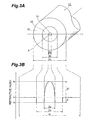
- FIG. 3A is a sectional view schematically showing the structure of a dispersion compensating optical fiber according to this embodiment
- FIG. 3B is a view showing the refractive index profile of the dispersion compensating optical fiber shown in FIG. 3A ;
- FIG. 4 is a graph showing the relationship between a DCF ratio R and the transmission loss of the entire optical transmission line
- FIG. 5 is a graph showing the relationship between the DCF ratio R and a nonlinear index ⁇ of the entire optical transmission line
- FIG. 6 is a graph showing the relationship between the DCF ratio R and a dispersion slope S total of the entire optical transmission line;
- FIG. 7 is a graph showing the relationship between the DCF ratio R and the transmission loss of the dispersion compensating optical fiber
- FIG. 8 is a graph showing the relationship between the DCF ratio R and an effective area A eff of the dispersion compensating optical fiber
- FIG. 9 is a graph showing the relationship between the DCF ratio R and a nonlinear refractive index n NL of the dispersion compensating optical fiber
- FIG. 10 is a graph showing the relationship between the DCF ratio R and the nonlinear index ⁇ of the entire optical transmission line and the relationship between the DCF ratio R and the effective area A eff of the dispersion compensating optical fiber;
- FIG. 11 is a graph showing the relationship between the DCF ratio R and the nonlinear index ⁇ of the entire optical transmission line when the leading wavelength is 1,650 nm;
- FIG. 12 is a graph showing the preferable range of a dispersion value D DCF and dispersion slope S DCF of the dispersion compensating optical fiber according to this embodiment
- FIG. 13 is a graph showing the relationship between the value ⁇ and the bending loss of the dispersion compensating optical fiber
- FIG. 14 is a graph showing an actual loss value ⁇ 1 ( ⁇ ) and theoretical loss value ⁇ 0 ( ⁇ ) of the dispersion compensating optical fiber;
- FIG. 15 is a graph showing a difference ⁇ ( ⁇ ) between the actual loss value ⁇ 1 ( ⁇ ) and the theoretical loss value ⁇ 0 ( ⁇ ) of the dispersion compensating optical fiber;
- FIG. 16 is a graph showing a logarithm log ( ⁇ ( ⁇ ));
- FIG. 17 is a graph showing the actual loss value ⁇ 1 ( ⁇ ) and theoretical loss value ⁇ 0 ( ⁇ ) of another dispersion compensating optical fiber;
- FIG. 18 is a graph showing the logarithm log ( ⁇ ( ⁇ )) of the difference ⁇ ( ⁇ ) between the actual loss value ⁇ 1 ( ⁇ ) and the theoretical loss value ⁇ 0 ( ⁇ ) of another dispersion compensating optical fiber;
- FIG. 19 is a graph showing the absolute dispersion value and span loss with respect to the leading wavelength of the dispersion compensating optical fiber
- FIG. 20 is a graph showing the effective area and nonlinear index with respect to the leading wavelength of the dispersion compensating optical fiber
- FIG. 21A is a perspective view showing the dispersion compensating optical fiber looped around the bobbin
- FIG. 21B is a view for explaining the size of the bobbin shown in FIG. 21A ;
- FIG. 22 is a perspective view showing the optical cable comprising the dispersion compensating optical fiber
- FIG. 23A is a sectional view showing the dispersion compensating module comprising the dispersion compensating optical fiber
- FIG. 23B is a plane view showing the dispersion compensating module shown in FIG. 23A ;
- FIG. 24A is a sectional view schematically showing another structure of the dispersion compensating optical fiber according to this embodiment.
- FIG. 24B is a view showing the refractive index profile of the dispersion compensating optical fiber shown in FIG. 24A .
- FIG. 25 is a view showing the arrangement of an optical transmission line and an optical transmission system according to another embodiment
- FIG. 26A is a sectional view showing a dispersion compensating device according to an embodiment.
- FIG. 26B is a plane view showing the dispersion compensating device shown in FIG. 26A
- FIG. 1 is a view showing the arrangement of an optical transmission line 1 according to this embodiment.
- the optical transmission line 1 of this embodiment is formed by connecting an upstream single-mode optical fiber (SMF) 11 to a downstream dispersion compensating optical fiber (DCF) 12 , and provided between a repeater 21 and a repeater 22 , thus an optical transmission system is constructed. At least one of the repeaters 21 and 22 may be a station.
- the single-mode optical fiber 11 has a zero dispersion wavelength in the 1.3- ⁇ m wavelength (1250 nm to 1350 nm) band and positive dispersion and a positive dispersion slope at a wavelength of 1,550 nm.
- the dispersion compensating optical fiber 12 has negative dispersion and a negative dispersion slope at the wavelength of 1,550 nm.
- the dispersion compensating optical fiber 12 can be comprised in an optical cable or in an optical module.
- a wavelength-multiplexed optical signal in the 1.55- ⁇ m wavelength band, which is output from the repeater 21 sequentially propagates through the single-mode optical fiber 11 and dispersion compensating optical fiber 12 and reaches the repeater 22 .
- L SMF the length
- D SMF unit: ps/nm/km
- S SMF unit: ps/nm 2 /km
- D DCF the dispersion value at the wavelength of 1,550 nm
- S DCF the dispersion slope at the wavelength of 1,550 nm.
- D total (unit: ps/nm/km) be the average dispersion value at the wavelength of 1,550 nm
- S total (unit: ps/nm 2 /km) be the average dispersion slope at the wavelength of 1,550 nm.
- D total R ⁇ D DCF +(1 ⁇ R ) ⁇ D SMF (2a)
- S total R ⁇ S DCF +(1 ⁇ R ) ⁇ S SMF (2b)
- the value of DCF ratio R ranges from 0.2 to 0.4.
- the dispersion value D SMF is about 17 to 19 ps/nm/km, and the dispersion slope S SMF is about 0.05 to 0.06 ps/nm 2 /km.
- the core region may be made of GeO 2 -doped silica while the cladding region may be made of pure silica, or the core region may be made of pure silica while the cladding region may be formed from F-doped silica.
- the single-mode optical fiber 11 is preferably a pure silica core fiber having a core region formed from pure silica which is not intentionally doped with an impurity such as GeO 2 . In this case, the loss in the entire optical transmission line 1 can be reduced by decreasing the Rayleigh scattering coefficient. As a result, degradation in waveform due to the nonlinear effect can be suppressed by reducing light incident power.
- FIG. 2A is a graph showing a specific example of the relationship between transmisson loss of a pure silica core fiber and the wavelength of propagation light.
- FIG. 2B is a graph showing the magnification of the part of FIG. 2A .
- transmission loss at the wavelength of 1,550 nm is preferably not more than 0.18 dB/km.
- the single-mode optical fiber 11 preferably has an effective area A eff of 100 ⁇ m 2 or more at the wavelength of 1,550 nm.
- a eff of 100 ⁇ m 2 or more at the wavelength of 1,550 nm.
- Table 1 shows the comparison result of loss and nonlinearity between four types of single-mode optical fibers 11 : a normal single-mode optical fiber (GeSM) having a core region doped with GeO 2 , a normal pure silica core fiber (PSCF), an A eff -increased GeSM having an increased effective area, and an A eff -increased PSCF having an increased effective area.
- GSM normal single-mode optical fiber
- PSCF normal pure silica core fiber
- an optical fiber having a loss of 0.270 dB/km, dispersion value D DCF of ⁇ 39.2 ps/nm/km, dispersion slope S DCF of ⁇ 0.060 ps/nm 2 /km, effective area A eff of 20.63 ⁇ m, and nonlinear refractive index n NL of 3.82 ⁇ 10 ⁇ 20 m 2 /W was used as the dispersion compensating optical fiber 12 .
- the equivalent A eff can be increased by about 5%.
- the equivalent A eff can be further increased by about 10%.
- the PSCF with increased A eff is used as the single-mode optical fiber 11 , the nonlinearity of the optical transmission line 1 can be effectively reduced.
- the dispersion compensating optical fiber 12 has the dispersion value D DCF and dispersion slope S DCF within the ranges of ⁇ 82 ⁇ D DCF ⁇ 29 (3a) 0.0023 ⁇ D DCF ⁇ S DCF ⁇ 0.033+0.0015 ⁇ D DCF (3b) More preferably, the dispersion value D DCF falls within the range of ⁇ 82 ⁇ D DCF ⁇ 36. The reason why this range is preferable will be described later.
- the leading wavelength of the dispersion compensating optical fiber 12 according to this embodiment falls within the range of 1,565 to 1,700 nm and, more preferably, 1,620 to 1,700 nm. The reason why this range is preferable will be described later.
- FIG. 3A is a sectional view schematically showing the structure of the dispersion compensating optical fiber 12 according to this embodiment.
- FIG. 3B is a view showing the refractive index profile of the dispersion compensating optical fiber 12 .
- the dispersion compensating optical fiber 12 has a core region 31 including an optical axis center X and having a refractive index n 1 , a first cladding region 32 surrounding the core region 31 and having a refractive index n 2 , and a second cladding region 33 surrounding the first cladding region 32 and having a refractive index n 3 .
- a relationship n 1 >n 3 >n 2 holds between the refractive indices.
- the dispersion compensating optical fiber 12 with such a structure can be implemented using silica glass as a base by, e.g., doping GeO 2 in the core region 31 and F in the first cladding region 32 .
- a relative refractive index difference ⁇ + of the core region 31 to the second cladding region 33 preferably falls within the range of 1.3% to 1.7%, and a relative refractive index difference ⁇ ⁇ of the first cladding region 32 to the second cladding region 33 preferably falls within the range of ⁇ 0.5% to ⁇ 0.2%.
- the relative refractive index difference is represented in percentage, and the refractive indices of the respective regions in the above definitions are not in order. Hence, when the relative refractive index difference has a negative value, the corresponding region has a refractive index lower than that of the second cladding region 33 .
- a nonlinear index ⁇ of the optical transmission line is defined as follows. More specifically, the nonlinear index ⁇ is obtained by integrating the phase modulation factor by self-phase modulation, i.e., a kind of nonlinear phenomenon across the total length of the optical transmission line and given by
- a eff 2 ⁇ ⁇ ⁇ ( ⁇ 0 ⁇ ⁇ E 2 ⁇ r ⁇ d r ) 2 / ( ⁇ 0 ⁇ ⁇ E 4 ⁇ r ⁇ d r ) ( 5 )
- E is the electric field accompanying the propagation light
- r is the radial distance from the core center.
- n NL is the nonlinear refractive index.
- the refractive index ⁇ N> of a medium under strong light changes depending on the light intensity.
- the refractive index ⁇ N> of the medium is given by the sum of the normal value ⁇ N 0 > and an increment proportional to the square of the optical field amplitude E.
- the proportional constant ⁇ N 2 > (unit: m 2 /W) of the second term is called a 2nd-order nonlinear refractive index.
- a nonlinear refractive index in this specification mainly means this 2nd-order nonlinear refractive index.
- Equation (4b) P(z) is the power of light, and ⁇ is the transmission loss in the optical transmission line.
- the effective area A eff (z), nonlinear refractive index n NL (z), and power P(z) are functions of a variable z indicating a position on the optical transmission line.
- P 0 is defined to obtain a predetermined power at the exit end of an optical transmission line with a predetermined length.
- a proportional coefficient k is defined such that the nonlinear index ⁇ of the single-mode optical fiber (an optical fiber having a core made of pure silica and a cladding made of F-doped silica) has a value “1”.
- the nonlinear index ⁇ defined so is 2.1 in a dispersion shift optical fiber (NZ-DSF) having a zero dispersion wavelength on the long wavelength side of 1,550 nm.
- NZ-DSF dispersion shift optical fiber
- the nonlinear optical phenomenon readily occurs.
- the value of nonlinear index ⁇ becomes small, the nonlinear optical phenomenon hardly occurs.
- the value of nonlinear index ⁇ in the optical transmission line is preferably as small as possible.
- the value of Equivalent A eff is preferably as large as possible.
- ⁇ 100 ⁇ ( S DCF /D DCF )/( S SMF /D SMF ) (6)
- both the dispersion value D total and dispersion slope S total in the entire optical transmission line 1 can be nullified by appropriately setting the DCF ratio R.
- the dispersion slope compensating ratio ⁇ is lower than 100%, both the dispersion value D total and dispersion slope S total in the entire optical transmission line 1 cannot be simultaneously nullified: when the dispersion value D total is zero, the dispersion slope S total is not zero.
- the dispersion value D DCF , dispersion slope S DCF , effective area A eff , and nonlinear refractive index n NL of the dispersion compensating optical fiber 12 were calculated for each value of relative refractive index difference ⁇ + of the core region 31 of the dispersion compensating optical fiber 12 such that the bending loss (bending diameter: 20 mm ⁇ , and wavelength: 1,550 nm) become 2 dB/m.
- the loss in dispersion compensating optical fiber 12 was calculated by obtaining the ⁇ + dependence from the past record and interpolating it, and the transmission loss and nonlinear index ⁇ of the entire optical transmission line 1 at that time were calculated.
- FIG. 4 is a graph showing the relationship between the DCF ratio R and the transmission loss of the entire optical transmission line 1 .
- FIG. 5 is a graph showing the relationship between the DCF ratio R and the nonlinear index ⁇ of the entire optical transmission line 1 .
- FIG. 6 is a graph showing the relationship between the DCF ratio R and the dispersion slope S total of the entire optical transmission line 1 .
- the dispersion slope compensating ratio ⁇ is changed to 30% (indicated by hollow square bullets), 50% (indicated by solid square bullet), 70% (indicated by hollow bullets), and 100% (indicated by solid bullets).
- FIG. 7 is a graph showing the relationship between the DCF ratio R and the transmission loss of the dispersion compensating optical fiber 12 .
- FIG. 8 is a graph showing the relationship between the DCF ratio R and the effective area A eff of the dispersion compensating optical fiber 12 .
- FIG. 9 is a graph showing the relationship between the DCF ratio R and the nonlinear refractive index n NL of the dispersion compensating optical fiber 12 .
- the dispersion slope compensating ratio ⁇ is 50%
- the bending loss (bending diameter: 20 mm ⁇ , and wavelength: 1,550 nm) is 2 dB/m.
- an A eff -increased pure silica core fiber (A eff -increased PSCF) having a core made of pure silica and a cladding made of F-doped silica was used.
- a eff -increased PSCF the transmission loss was 0.175 dB/km
- the effective area A eff was 110 ⁇ m 2
- the nonlinear refractive index n NL was 2.8 ⁇ 10 ⁇ 20 m 2 /W
- the dispersion value D SMF was 18.7 ps/nm/km
- the dispersion slope S SMF was 0.057 ps/nm 2 /km.
- the dispersion slope compensating ratio ⁇ is preferably as low as possible.
- the upper limit of the preferable range of the dispersion slope compensating ratio ⁇ is preferably 80% and, more preferably, 70%.
- the dispersion slope compensating ratio ⁇ is preferably as high as possible.
- the lower limit of the preferable range of the dispersion slope compensating ratio ⁇ is preferably 20% and, more preferably, 30%.
- the preferable range of the dispersion slope compensating ratio ⁇ is 20% (more preferably, 30%) to 80% (more preferably, 70%).
- the ratio R of the dispersion compensating optical fiber 12 having a loss larger than that of the single-mode optical fiber 11 becomes high, the transmission loss and nonlinear index ⁇ of the entire optical transmission line 1 have dependence on the DCF ratio R, as will be described below.
- the transmission loss of the entire optical transmission line 1 is small in the region where the DCF ratio R is 20% or more (more preferably, 25% or more).
- the DCF ratio R is 40% or less (more preferably, 35% or less)
- the nonlinear index ⁇ of the entire optical transmission line 1 is low.
- the DCF ratio R preferably falls within the range of 20% (more preferably, 25%) to 40% (more preferably, 35%)
- the preferable ranges of the dispersion slope compensating ratio ⁇ and DCF ratio R of the optical transmission line 1 are satisfied.
- FIG. 10 is a graph showing the relationship between the DCF ratio R and the nonlinear index ⁇ of the entire optical transmission line 1 and the relationship between the DCF ratio R and the effective area A eff of the dispersion compensating optical fiber 12 .
- the dispersion slope compensating ratio ⁇ is changed to 30% (indicated by hollow square bullets), 50% (indicated by solid square bullet), 70% (indicated by hollow bullets), and 100% (indicated by solid bullets).
- the higher the DCF ratio R becomes the larger the effective area A eff of the dispersion compensating optical fiber 12 becomes.
- the effective area A eff of the dispersion compensating optical fiber 12 is 14 ⁇ m 2 or more.
- an optical fiber having the refractive index profile shown in FIGS. 2A and 2B was used as the dispersion compensating optical fiber 12 of the optical transmission line 1 .
- the relative refractive index difference ⁇ ⁇ between the first cladding region 32 and the second cladding region 33 was fixed to ⁇ 0.36%.
- the dispersion value, dispersion slope, and effective area A eff when the leading wavelength of the dispersion compensating optical fiber was fixed were calculated while changing the relative refractive index difference ⁇ + , and the nonlinear index at each relative refractive index difference ⁇ + was calculated on the basis of equations (4a) and (4b).
- the single-mode optical fiber 11 an A eff -increased pure silica core fiber (A eff -increased PSCF) having a core made of pure silica and a cladding made of F-doped silica was used.
- the transmission loss was 0.175 dB/km
- the effective area A eff was 110 ⁇ m 2
- the nonlinear refractive index n NL was 2.8 ⁇ 10 ⁇ 20 m 2 /W
- the dispersion value D SMF was 18.7 ps/nm/km
- the dispersion slope S SMF was 0.057 ps/nm 2 /km.
- one span was set to 50 km, and the average dispersion in each span was ⁇ 2 ps/nm/km, thereby determining the lengths of the single-mode optical fiber 11 and dispersion compensating optical fiber 12 .
- the average transmission loss and average dispersion slope were average values in the entire optical transmission line 1 between stations (repeaters 21 and 22 in FIG. 1 ). Under these conditions, the nonlinear index was calculated on the basis of equation (4a).
- FIG. 11 is a graph showing the relationship between the DCF ratio R and the nonlinear index ⁇ of the entire optical transmission line when the leading wavelength is 1,650 nm.
- the dispersion slope compensating ratio ⁇ is changed to 30% (indicated by hollow square bullets), 50% (indicated by solid square bullet), and 60% (indicated by solid triangles).
- the DCF ratio R is about 25%, the nonlinear index is minimum, and the nonlinearity in the optical transmission line 1 is minimum.
- the preferable range of the DCF ratio R capable of suppressing the nonlinearity is 0.2 to 0.4.
- the preferable range of the dispersion value D DCF of the dispersion compensating optical fiber is ⁇ 82 ⁇ D DCF ⁇ 29
- This dispersion compensating optical fiber 12 is preferable for long-distance large-capacity transmission because the nonlinear index of the entire optical transmission line 1 can be sufficiently suppressed when the optical transmission line is formed by connecting the dispersion compensating optical fiber 12 to the single-mode optical fiber 11 .
- the preferable range of the dispersion value D DCF of the dispersion compensating optical fiber 12 is ⁇ 82 ⁇ D DCF ⁇ 36
- the preferable range of the dispersion slope S DCF of the dispersion compensating optical fiber 12 can be obtained on the basis of the dispersion slope S total of the entire optical transmission line 1 , the dispersion slope S SMF of the single-mode optical fiber, and the DCF ratio R.
- the dispersion slope S total of the entire optical transmission line 1 is preferably 0.03 ps/nm 2 /km, S DCF ⁇ 0.03 ⁇ (1 ⁇ R ) S SMF ⁇ /R (7)
- the dispersion slope compensating ratio ⁇ defined by equation (6) must be 70% or less ( FIG. 5 ).
- the preferable range of a loss ⁇ DCF of the dispersion compensating optical fiber 12 is obtained in the following way.
- ⁇ SMF be the loss of the single-mode optical fiber
- ⁇ total (1 ⁇ R ) ⁇ SMF +R ⁇ DCF (9)
- the loss ⁇ SMF is preferably about 0.175 dB/km, and the average loss ⁇ total is preferably 0.24 dB/km or less
- the loss ⁇ DCF of the dispersion compensating optical fiber 12 is preferably 0.5 dB/km or less.
- the loss ⁇ DCF of the dispersion compensating optical fiber 12 is more preferably 0.4 dB/km or less.
- FIG. 12 is a graph showing the preferable ranges (region A indicated by a rectangle) of the dispersion value D DCF and dispersion slope S DCF of the dispersion compensating optical fiber 12 according to this embodiment at the wavelength of 1,550 nm.
- the range (region B indicated by an ellipse) of the dispersion value and dispersion slope of a conventional dispersion compensating optical fiber at the wavelength of 1,550 nm, and the dispersion value and dispersion slope (indicated by a solid square bullet) of the single-mode optical fiber (SMF) are also shown.
- This graph also shows the dispersion values and dispersion slopes (indicated by hollow bullets and hollow triangles) of eight examples (to be described later) of the dispersion compensating optical fiber 12 according to this embodiment.
- the bending loss (bending diameter: 20 mm ⁇ , and wavelength: 1,550 nm) and transmission loss of the dispersion compensating optical fiber 12 will be described next. Assume that the core region 31 (0 ⁇ r ⁇ a) of the dispersion compensating optical fiber 12 shown in FIGS. 3A and 3B has an index distribution n(r) of ⁇ th power, which is given by
- n ⁇ ( r ) n 1 ⁇ ⁇ 1 - 2 ⁇ ⁇ ⁇ ⁇ ( r a ) ⁇ ⁇ 1 / 2 (10a)
- ⁇ n 1 2 - n 2 2 2 ⁇ n 1 2 (10b)
- r is the radial distance from the center of the core region 31
- n 2 is the refractive index of the first cladding region 32 .
- the relative refractive index difference ⁇ + of the core region 31 is +1.6%
- the relative refractive index difference ⁇ ⁇ of the first cladding region 32 is ⁇ 0.36%.
- the dispersion value D DCF of the dispersion compensating optical fiber 12 is ⁇ 50 ps/nm/km, and the dispersion slope compensating ratio ⁇ is 50%.
- FIG. 13 is a graph showing the relationship between the value ⁇ and the bending loss of the dispersion compensating optical fiber 12 . As is apparent from this graph, the larger the value ⁇ is, the smaller the bending loss of the dispersion compensating optical fiber 12 is. When the value ⁇ is 2.0 or more, the bending loss of the dispersion compensating optical fiber 12 is suitably 2 dB/m or less. At this time, the transmission loss of the dispersion compensating optical fiber 12 is suitably 0.4 dB/km or less.
- a microbend loss is a loss generated when a side pressure is applied to the optical fiber to slightly bend the optical fiber axis.
- the microbend loss is measured as a loss that increases when the optical fiber is wound on a 280-mm ⁇ bobbin with No. 1,000 sandpaper at a tensile force of 100 g.
- the outer diameter (optical fiber diameter) or coating diameter of the second cladding region 33 when the outer diameter (optical fiber diameter) or coating diameter of the second cladding region 33 is large, a cable formed from the optical fiber undesirably becomes bulky.
- the outer diameter (optical fiber diameter) of the second cladding region 33 when the outer diameter (optical fiber diameter) of the second cladding region 33 is large, the rupture probability of the optical fiber becomes high.
- the coating diameter preferably falls within the range of 235 to 415 ⁇ m.
- the outer diameter (optical fiber diameter) of the second cladding region 33 preferably falls within the range of 115 to 200 ⁇ m.
- leading wavelength preferably falls within the range of 1,565 to 1,700 nm and, more preferably, 1,620 to 1,700 nm will be described next.
- Losses unique to an optical fiber include a loss due to Rayleigh scattering, a loss due to absorption, and a loss due to structure mismatching.
- ⁇ unit: ⁇ m
- A the Rayleigh scattering coefficient
- B the Rayleigh scattering coefficient
- B the loss due to structure mismatching.
- the loss (actual loss value ⁇ 1 ( ⁇ )) in actual use of the optical fiber may be larger than the theoretical loss value ⁇ 0 ( ⁇ ). This phenomenon is caused by bending and readily occurs as the wavelength ⁇ becomes long, and especially, in the dispersion compensating optical fiber. If the actual loss value ⁇ 1 of the optical fiber becomes large in the use wavelength band, an optical transmission system using this optical fiber as an optical transmission line requires a number of optical amplifiers for amplifying an optical signal, resulting in high cost. Alternatively, pulses readily deform due to the nonlinear phenomenon which occurs when high-power light is incident. Hence, to prevent the transmission loss from increasing in the use wavelength band, the leading wavelength of the dispersion compensating optical fiber 12 must be defined. The preferable range of the leading wavelength of the dispersion compensating optical fiber 12 is obtained in the following way.
- the “leading wavelength” is defined as follows.
- FIGS. 14 to 16 are explanatory views of the leading wavelength.
- the solid line indicates the actual loss value ⁇ 1 ( ⁇ ) of the dispersion compensating optical fiber 12
- the broken line indicates the theoretical loss value ⁇ 0 ( ⁇ ).
- the theoretical loss value ⁇ 0 ( ⁇ ) of the dispersion compensating optical fiber 12 is minimum near a wavelength band of 1,500 to 1,650 nm.
- the actual loss value ⁇ 1 ( ⁇ ) of the dispersion compensating optical fiber 12 almost matches the theoretical loss value ⁇ 0 ( ⁇ ) near a wavelength of 1,550 nm.
- a wavelength band of 1,520 to 1,565 nm is used as a signal wavelength band for an optical transmission system.
- a wavelength band of 1,565 to 1,620 nm may also be used.
- the actual loss value ⁇ 1 ( ⁇ ) is larger than the theoretical loss value ⁇ 0 ( ⁇ ) near a wavelength of 1,380 nm due to the hydroxyl group and also larger than the theoretical loss value ⁇ 0 ( ⁇ ) near a wavelength of 1,580 nm.
- FIG. 15 is a graph showing a difference ⁇ ( ⁇ ) between the actual loss value ⁇ 1 ( ⁇ ) and the theoretical loss value ⁇ 0 ( ⁇ ) of the dispersion compensating optical fiber 12 shown in FIG. 14 .
- FIG. 16 is a graph showing a logarithm log ( ⁇ ( ⁇ )) of this difference.
- the logarithm log ( ⁇ ( ⁇ )) and the wavelength ⁇ have an almost linear relationship when the wavelength is 1,580 nm or more.
- the minimum wavelength corresponding to a logarithm log ( ⁇ ( ⁇ )) of ⁇ 2 or more i.e., the value ⁇ ( ⁇ ) is 10 mdB/km or more
- the leading wavelength is 1,582 nm.
- the transmission loss is 0.267 dB/km
- the dispersion value is ⁇ 55.12 ps/nm/km
- the dispersion slope is ⁇ 0.049 ps/nm 2 /km
- the mode field diameter (MFD) is 5.4 ⁇ m
- the effective area A eff is 21.9 ⁇ m 2
- the bending loss (20 ⁇ ) is 4.1 dB/m.
- FIGS. 17 and 18 are explanatory views of the leading wavelength of another dispersion compensating optical fiber 12 .
- the solid line indicates the actual loss value ⁇ 1 ( ⁇ ) of the dispersion compensating optical fiber 12
- the broken line indicates the theoretical loss value ⁇ 0 ( ⁇ ).
- the theoretical loss value ⁇ 0 ( ⁇ ) of the dispersion compensating optical fiber 12 is minimum near a wavelength band of 1,500 to 1,650 nm.
- the actual loss value ⁇ 1 ( ⁇ ) of the dispersion compensating optical fiber 12 almost matches the theoretical loss value ⁇ 0 ( ⁇ ) near a wavelength of 1,520 to 1,620 nm.
- a wavelength band of 1,520 to 1,620 nm is used as a signal wavelength band for an optical transmission system.
- the actual loss value ⁇ 1 ( ⁇ ) is larger than the theoretical loss value ⁇ 0 ( ⁇ ) near a wavelength of 1,380 nm due to the hydroxyl group and also larger than the theoretical loss value ⁇ 0 ( ⁇ ) near a wavelength of 1,630 nm.
- FIG. 18 is a graph showing the logarithm log ( ⁇ ( ⁇ )) of the difference ⁇ ( ⁇ ) between the actual loss value ⁇ 1 ( ⁇ ) and the theoretical loss value ⁇ 0 ( ⁇ ).
- the logarithm log ( ⁇ ( ⁇ )) and the wavelength ⁇ have an almost linear relationship when the wavelength is 1,630 nm or more.
- the leading wavelength as the minimum wavelength corresponding to a logarithm log ( ⁇ ( ⁇ )) of ⁇ 2 or more i.e., the value ⁇ ( ⁇ ) is 10 mdB/km or more
- the value ⁇ ( ⁇ ) is 10 mdB/km or more
- the transmission loss is 0.256 dB/km
- the dispersion value is ⁇ 41.76 ps/nm/km
- the dispersion slope is ⁇ 0.0741 ps/nm 2 /km
- the mode field diameter (MFD) is 5.1 ⁇ m
- the effective area A eff is 19.5 ⁇ m 2
- the bending loss (20 ⁇ ) is 0.7 dB/m.
- FIG. 19 is a graph showing the absolute dispersion value (indicated by the solid line) and span loss (indicated by the broken line) with respect to the leading wavelength of the dispersion compensating optical fiber 12 .
- FIG. 20 is a graph showing the effective area (indicated by the solid line) and nonlinear index (indicated by the broken line) with respect to the leading wavelength of the dispersion compensating optical fiber 12 .
- the absolute dispersion value and effective area are values in the dispersion compensating optical fiber 12 at a wavelength of 1,550 nm.
- the span loss and nonlinear index are values in the optical transmission line at the wavelength of 1,550 nm.
- both the average transmission loss (span loss) of the entire optical transmission line 1 and the nonlinear index undesirably increase.
- the leading wavelength of the dispersion compensating optical fiber 12 must have a predetermined value or less.
- the upper limit of the preferable range of the leading wavelength of the dispersion compensating optical fiber 12 is 1,700 nm.
- the leading wavelength of the dispersion compensating optical fiber 12 is included in the use wavelength band.
- the actual loss value ⁇ 1 ( ⁇ ) of the dispersion compensating optical fiber 12 undesirably increases.
- the lower limit of the preferable range of the leading wavelength of the dispersion compensating optical fiber 12 matches the upper limit of the use wavelength band.
- the leading wavelength of the dispersion compensating optical fiber 12 preferably falls within the range of 1,565 to 1,700 nm. If the use wavelength band includes not only the C band but also the L band (1,565 to 1,620 nm), the leading wavelength of the dispersion compensating optical fiber 12 preferably falls within the range of 1,620 to 1,700 nm. When the leading wavelength of the dispersion compensating optical fiber 12 is present in this preferable range, the transmission loss of the dispersion compensating optical fiber 12 becomes sufficiently small in the use wavelength band. In addition, both the transmission loss and nonlinear index of the optical transmission line 1 formed by connecting the single-mode optical fiber 11 and dispersion compensating optical fiber 12 also become sufficiently small.
- the dispersion compensating optical fiber 12 is preferably connected to the single-mode optical fiber 11 to construct the optical transmission line 1 .
- An optical transmission system having this optical transmission line 1 requires a small number of optical amplifiers for amplifying an optical signal, resulting in low cost.
- the transmission loss is small, the input power can be reduced.
- the nonlinear index of the entire optical transmission line 1 can be suppressed sufficiently small, the nonlinear optical phenomenon hardly occurs, and the optical transmission line can be suitably used for long-distance large-capacity transmission.
- the actual loss value ⁇ 1 ( ⁇ ) of the dispersion compensating optical fiber 12 according to this embodiment is measured in a state that the fiber 12 is looped around a bobbin, or in a state that the fiber 12 is comprised in an optical cable, or in a state that the fiber 12 is comprised in an optical module.
- the leading wavelength of the dispersion compensating optical fiber 12 with the dispersion of ⁇ 40 ps/nm/km, the dispersion slope of ⁇ 0.12 ps/nm 2 /km, the relative dispersion slope (the ratio of the dispersion slope to the dispersion) of 0.003 nm ⁇ 1 , and the effective area A eff of 28 ⁇ m 2 , at a wavelength of 1,550 nm is measured.
- the actual loss value ⁇ 1 ( ⁇ ) is measured in a state that the dispersion compensating optical fiber 12 is looped around a flanged bobbin 40 with the barrel diameter R of 280 mm and the barrel width W of 300 mm under tension of 50 g shown in FIGS. 21A and 21B , and the leading wavelength measured in this case is 1,600 nm. Furthermore, the actual loss value ⁇ 1 ( ⁇ ) is measured in a state that the dispersion compensating optical fiber 12 is comprised in an optical cable 50 shown in FIG. 22 . The fiber 12 is loosely housed in a tube 52 filled with gel material 54 . The leading wavelength measured in this case is 1,640 nm.
- Such a dispersion compensating optical fiber 12 is preferable for forming an optical transmission line by being optically connected to an optical fiber with positive dispersion at a use wavelength.
- the relative dispersion slope of the fiber 12 at a wavelength of 1,550 nm is preferably 0.0023 to 0.0043 nm ⁇ 1 and the dispersion value at a wavelength of 1,550 nm is preferably ⁇ 82 to ⁇ 29 ps/nm/km like the fiber explained in the above first measurement example.
- the leading wavelength of the dispersion compensating optical fiber 12 with the dispersion of ⁇ 80 ps/nm/km, the dispersion slope of ⁇ 0.80 ps/nm 2 /km, the relative dispersion slope of 0.010 nm ⁇ 1 , and the effective area A eff of 17 ⁇ m 2 , at a wavelength of 1,550 nm is measured.
- the actual loss value ⁇ 1 ( ⁇ ) is measured in a state that the dispersion compensating optical fiber 12 is looped around a flanged bobbin 40 with the barrel diameter R of 170 mm and the barrel width W of 100 mm under tension of 40 g shown in FIGS. 21A and 21B , and the leading wavelength measured in this case is 1,570 nm. Furthermore, the actual loss value ⁇ 1 ( ⁇ ) is measured in a state that the dispersion compensating optical fiber 12 is comprised in a dispersion compensating module 60 shown in FIGS. 23A and 23B . The fiber 12 is loosely housed in a case 62 filled with gel material 64 . The leading wavelength measured in this case is 1,610 nm.
- Such a dispersion compensating optical fiber 12 is preferable for forming an optical transmission line by being optically connected to an optical fiber with positive dispersion at a use wavelength.
- the relative dispersion slope of the fiber 12 at a wavelength of 1,550 nm is preferably not less than 0.006 nm ⁇ 1 and the dispersion value at a wavelength of 1,550 nm is preferably ⁇ 82 to ⁇ 29 ps/nm/km like the fiber explained in the above second measurement example.
- FIG. 24A is a sectional view schematically showing another structure of the dispersion compensating optical fiber 12 according to this embodiment.
- FIG. 24B is a view showing the refractive index profile of the dispersion compensating optical fiber 12 . As shown in FIGS.
- the dispersion compensating optical fiber 12 may have the core region 31 including the optical axis center X and having the refractive index n 1 , the first cladding region 32 surrounding the core region 31 and having the refractive index n 2 , the second cladding region 33 surrounding the first cladding region 32 and having the refractive index n 3 , and a third cladding region 34 surrounding the second cladding region 33 and having a refractive index n 4 .
- a relationship n 1 >n 3 >n 4 >n 2 holds between the refractive indices.
- the dispersion compensating optical fiber 12 with such a structure can be implemented using silica glass as a base by, e.g., doping appropriate doses of GeO 2 in the core region 31 and second cladding region 33 , and F in the first cladding region 32 .
- the dispersion value D DCF and dispersion slope S DCF at the wavelength of 1,550 nm can satisfy equations (3a) and (3b).
- the relative refractive index difference ⁇ + of the core region 31 to the third cladding region 34 is preferably 1.3% to 1.7%, and the relative refractive index difference ⁇ ⁇ of the first cladding region 32 to the third cladding region 34 is preferably ⁇ 0.5% to ⁇ 0.2%.
- the relative refractive index difference is represented in percentage, and the refractive indices of the respective regions in the above definitions are not in order. Hence, when the relative refractive index difference has a negative value, the corresponding region has a refractive index lower than that of the third cladding region 34 .
- Each of the first to fifth examples of the dispersion compensating optical fiber 12 has the refractive index profile shown in FIGS. 3A and 3B .
- Each of the sixth to eighth examples of the dispersion compensating optical fiber 12 has the refractive index profile shown in FIGS. 24A and 24B .
- the first example of the dispersion compensating optical fiber 12 has the refractive index profile shown in FIGS. 3A and 3B .
- the diameter 2 a of the core region 31 is 4.34 ⁇ m
- the outer diameter 2 b of the first cladding region 32 is 9.24 ⁇ m
- the outer diameter 2 c of the second cladding region 33 is 125 ⁇ m
- the relative refractive index difference ⁇ + of the core region 31 is +1.35%
- the relative refractive index difference ⁇ ⁇ of the first cladding region 32 is ⁇ 0.36%.
- the dispersion value D DCF of this dispersion compensating optical fiber 12 is ⁇ 35.5 ps/nm/km, and the dispersion slope S DCF is ⁇ 0.076 ps/nm 2 /km, which satisfy equations (3a) and (3b).
- the effective area A eff of this dispersion compensating optical fiber 12 is 19.66 ⁇ m 2
- the nonlinear refractive index n NL is 3.83 ⁇ 10 ⁇ 20 m 2 /W
- the transmission loss is 0.27 dB/km.
- the second example of the dispersion compensating optical fiber 12 has the refractive index profile shown in FIGS. 3A and 3B .
- the diameter 2 a of the core region 31 is 3.30 ⁇ m
- the outer diameter 2 b of the first cladding region 32 is 8.24 ⁇ m
- the outer diameter 2 c of the second cladding region 33 is 125 ⁇ m
- the relative refractive index difference ⁇ + of the core region 31 is +1.70%
- the relative refractive index difference ⁇ ⁇ of the first cladding region 32 is ⁇ 0.36%.
- the dispersion value D DCF of this dispersion compensating optical fiber 12 is ⁇ 68.2 ps/nm/km, and the dispersion slope S DCF is ⁇ 0.145 ps/nm 2 /km, which satisfy equations (3a) and (3b).
- the effective area A eff of this dispersion compensating optical fiber 12 is 16.31 ⁇ m 2
- the nonlinear refractive index n NL is 4.13 ⁇ 10 ⁇ 20 m 2 /W
- the transmission loss is 0.35 dB/km.
- the third example of the dispersion compensating optical fiber 12 has the refractive index profile shown in FIGS. 3A and 3B .
- the diameter 2 a of the core region 31 is 4.35 ⁇ m
- the outer diameter 2 b of the first cladding region 32 is 8.20 ⁇ m
- the outer diameter 2 c of the second cladding region 33 is 125 ⁇ m
- the relative refractive index difference ⁇ + of the core region 31 is +1.35%
- the relative refractive index difference ⁇ ⁇ of the first cladding region 32 is ⁇ 0.36%.
- the dispersion value D DCF of this dispersion compensating optical fiber 12 is ⁇ 39.2 ps/nm/km, and the dispersion slope S DCF is ⁇ 0.060 ps/nm 2 /km, which satisfy equations (3a) and (3b)
- the effective area A eff of this dispersion compensating optical fiber 12 is 20.63 ⁇ m 2
- the nonlinear refractive index n NL is 3.82 ⁇ 10 ⁇ 20 m 2 /W
- the transmission loss is 0.27 dB/km.
- the fourth example of the dispersion compensating optical fiber 12 has the refractive index profile shown in FIGS. 3A and 3B .
- the diameter 2 a of the core region 31 is 3.29 ⁇ m
- the outer diameter 2 b of the first cladding region 32 is 7.32 ⁇ m
- the outer diameter 2 c of the second cladding region 33 is 125 ⁇ m
- the relative refractive index difference ⁇ + of the core region 31 is +1.70%
- the relative refractive index difference ⁇ ⁇ of the first cladding region 32 is ⁇ 0.36%.
- the dispersion value D DCF of this dispersion compensating optical fiber 12 is ⁇ 71.8 ps/nm/km, and the dispersion slope S DCF is ⁇ 0.109 ps/nm 2 /km, which satisfy equations (3a) and (3b).
- the effective area A eff of this dispersion compensating optical fiber 12 is 17.16 ⁇ m 2
- the nonlinear refractive index n NL is 4.14 ⁇ 10 ⁇ 20 m 2 /W
- the transmission loss is 0.35 dB/km.
- the fifth example of the dispersion compensating optical fiber 12 has the refractive index profile shown in FIGS. 3A and 3B .
- the diameter 2 a of the core region 31 is 4.35 ⁇ m
- the outer diameter 2 b of the first cladding region 32 is 7.50 ⁇ m
- the outer diameter 2 c of the second cladding region 33 is 125 ⁇ m
- the relative refractive index difference ⁇ + of the core region 31 is +1.35%
- the relative refractive index difference ⁇ ⁇ of the first cladding region 32 is ⁇ 0.36%.
- the dispersion value D DCF of this dispersion compensating optical fiber 12 is ⁇ 40.0 ps/nm/km, and the dispersion slope S DCF is ⁇ 0.0366 ps/nm 2 /km, which satisfy equations (3a) and (3b).
- the effective area A eff of this dispersion compensating optical fiber 12 is 21.45 ⁇ m 2
- the nonlinear refractive index n NL is 3.82 ⁇ 10 ⁇ 20 m 2 /W
- the transmission loss is 0.27 dB/km.
- the sixth example of the dispersion compensating optical fiber 12 has the refractive index profile shown in FIGS. 24A and 24B .
- the diameter 2 a of the core region 31 is 4.44 ⁇ m
- the outer diameter 2 b of the first cladding region 32 is 8.88 ⁇ m
- an outer diameter 2 c of the second cladding region 33 is 14.80 ⁇ m
- the outer diameter 2 d of the third cladding region 34 is 125 ⁇ m
- the relative refractive index difference ⁇ + of the core region 31 is +1.50%
- the relative refractive index difference ⁇ ⁇ of the first cladding region 32 is ⁇ 0.37%
- the relative refractive index difference ⁇ 3 of the second cladding region 33 is +0.20%.
- the dispersion value D DCF of this dispersion compensating optical fiber 12 is ⁇ 57.94 ps/nm/km, and the dispersion slope S DCF is ⁇ 0.106 ps/nm 2 /km, which satisfy equations (3a) and (3b).
- the effective area A eff of this dispersion compensating optical fiber 12 is 21.59 ⁇ m 2
- the nonlinear refractive index n NL is 3.88 ⁇ 10 ⁇ 20 m 2 /W
- the transmission loss is 0.3 dB/km.
- the seventh example of the dispersion compensating optical fiber 12 has the refractive index profile shown in FIGS. 24A and 24B .
- the diameter 2 a of the core region 31 is 5.41 ⁇ m
- the outer diameter 2 b of the first cladding region 32 is 8.20 ⁇ m
- the outer diameter 2 c of the second cladding region 33 is 16.40 ⁇ m
- the outer diameter 2 d of the third cladding region 34 is 125 ⁇ m
- the relative refractive index difference ⁇ + of the core region 31 is +1.35%
- the relative refractive index difference ⁇ ⁇ of the first cladding region 32 is ⁇ 0.50%
- the relative refractive index difference ⁇ 3 of the second cladding region 33 is +0.20%.
- the dispersion value D DCF of this dispersion compensating optical fiber 12 is ⁇ 38.14 ps/nm/km, and the dispersion slope S DCF is ⁇ 0.066 ps/nm 2 /km, which satisfy equations (3a) and (3b).
- the effective area A eff of this dispersion compensating optical fiber 12 is 22.51 ⁇ m 2
- the nonlinear refractive index n NL is 3.83 ⁇ 10 ⁇ 20 m 2 /W
- the transmission loss is 0.3 dB/km.
- the eighth example of the dispersion compensating optical fiber 12 has the refractive index profile shown in FIGS. 24A and 24B .
- the diameter 2 a of the core region 31 is 3.70 ⁇ m
- the outer diameter 2 b of the first cladding region 32 is 11.40 ⁇ m
- the outer diameter 2 c of the second cladding region 33 is 14.80 ⁇ m
- the outer diameter 2 d of the third cladding region 34 is 125 ⁇ m
- the relative refractive index difference ⁇ + of the core region 31 is +1.65%
- the relative refractive index difference ⁇ ⁇ of the first cladding region 32 is ⁇ 0.20%
- the relative refractive index difference ⁇ 3 of the second cladding region 33 is +0.40%.
- the dispersion value D DCF of this dispersion compensating optical fiber 12 is ⁇ 76.68 ps/nm/km, and the dispersion slope S DCF is ⁇ 0.094 ps/nm 2 /km, which satisfy equations (3a) and (3b).
- the effective area A eff of this dispersion compensating optical fiber 12 is 24.27 ⁇ m 2
- the nonlinear refractive index n NL is 3.90 ⁇ 10 ⁇ 20 m 2 /W
- the transmission loss is 0.33 dB/km.
- the dispersion compensating optical fiber 12 is connected, at an appropriate length ratio, to the single-mode optical fiber 11 having a zero dispersion wavelength in the 1.3- ⁇ m band and positive dispersion at the wavelength of 1,550 nm to form the optical transmission line 1 which reduces both the transmission loss and nonlinear index.
- the optical transmission line 1 having this arrangement has a low refractive index and low nonlinear index, the nonlinear optical phenomenon is suppressed. Hence, the optical transmission line is suitable to long-distance large-capacity transmission.
- FIG. 25 is a view showing the arrangement of an optical transmission line 70 according to this embodiment.
- the optical transmission line 70 of this embodiment is formed by connecting an upstream single-mode optical fiber (SMF) 11 to a downstream dispersion compensating device 72 , and provided between a repeater 21 and a repeater 22 , thus an optical transmission system is constructed. At least one of the repeaters 21 and 22 may be a station.
- the single-mode optical fiber 11 has positive dispersion and positive dispersion slope at a wavelength of 1,550 nm.
- the dispersion compensating device 72 is formed by fusion-splicing and optically connecting a plurality of optical fibers.
- the dispersion compensating device 72 has negative dispersion and a negative dispersion slope at the wavelength of 1,550 nm.
- At least one of a plurality of optical fibers is a dispersion compensating optical fiber.
- the dispersion compensating device 72 is constructed by optically connecting one dispersion compensating optical fiber 74 and one single-mode optical fiber 76 .
- the dispersion compensating device 72 can be comprised in an optical module.
- the leading wavelength of the optically connected optical fibers 74 , 76 as a whole preferably falls within the range of 1,565 to 1,700 nm and, more preferably, 1,620 to 1,700 nm
- relative dispersion slope (RDS: dispersion slope/dispersion) is not less than 0.006 nm ⁇ 1 .
- RDS dispersion slope/dispersion
- an optical transmission line 70 which has sufficiently small transmission loss and nonlinear index can be formed.
- the use wavelength band is the C band (1,520 to 1,565 nm)
- the leading wavelength of the dispersion compensating device 72 preferably falls within the range of 1,565 to 1,700 nm.
- the use wavelength band includes not only the C band but also the L band (1,565 to 1,620 nm)
- the leading wavelength of the dispersion compensating device 72 preferably falls within the range of 1,620 to 1,700 nm.
- the actual loss value ⁇ 1 ( ⁇ ) of the dispersion compensating device 72 according to this embodiment is measured in a state that the device 72 is comprised in an optical module.
- the leading wavelength of the dispersion compensating device 72 is measured.
- the device 72 is formed by connecting the dispersion compensating optical fiber with the dispersion of ⁇ 60 ps/nm/km, the dispersion slope of ⁇ 0.80 ps/nm 2 /km, and the effective area A eff of 18 ⁇ m, at a wavelength of 1,550 nm and a single-mode optical fiber with the dispersion of +17 ps/nm/km, the dispersion slope of +0.06 ps/nm 2 /km, and the effective area A eff of 85 ⁇ m, at a wavelength of 1,550 nm.
- the ratio of the length of the dispersion compensating optical fiber to the length of the single-mode optical fiber is 2/3.
- the average dispersion of the overall fibers is ⁇ 13.8 ps/nm/km, the average dispersion slope of the overall fibers is ⁇ 0.284 ps/nm 2 /km, and the average relative dispersion slope of the overall fibers is 0.02 nm ⁇ 1 at a wavelength of 1,550 nm.
- the actual loss value ⁇ 1 ( ⁇ ) is measured in a state that the optical fibers 74 , 76 is comprised in an optical module shown in FIGS. 26A and 26B .
- the fibers 74 , 76 is loosely housed in a case 62 filled with gel material 64 .
- the leading wavelength measured in this case is 1,590 nm.
- Such a dispersion compensating device 72 is preferable for forming an optical transmission line by being optically connected to an optical fiber with positive dispersion at a use wavelength.
Landscapes
- Chemical & Material Sciences (AREA)
- Dispersion Chemistry (AREA)
- Physics & Mathematics (AREA)
- General Physics & Mathematics (AREA)
- Optics & Photonics (AREA)
- Optical Communication System (AREA)
Abstract
Description
R=L DCF/(L DCF +L SMF) (1)
At this time,
D total =R·D DCF+(1−R)·DSMF (2a)
S total =R·S DCF+(1−R)·SSMF (2b)
In the
| TABLE 1 | |||
| Span | |||
| Between | |||
| Single-Mode Optical Fiber (SMF) | Repeaters | ||
| Nonlinear | Equivalent | |||||
| Disper- | Refractive | Effective | ||||
| sion | Effective | Index nNL | area | |||
| Loss | DSMF[ps/ | area | [×10−20 | Equivalent | ||
| [dB/km] | nm/km] | Aeff [μm2] | m2/W] | Aeff [μm2] | ||
| GeSM | 0.185 | 17 | 80 | 3.0 | 50.7 |
| PSCF | 0.170 | 18 | 80 | 2.8 | 53.4 |
| Aeff-In- | 0.185 | 17 | 100 | 3.0 | 57.4 |
| creased | |||||
| GeSM | |||||
| AeffIn- | 0.170 | 18 | 100 | 2.8 | 59.4 |
| creased | |||||
| PSCF | |||||
−82≦D DCF≦−29 (3a)
0.0023×D DCF ≦S DCF≦0.033+0.0015×D DCF (3b)
More preferably, the dispersion value DDCF falls within the range of −82≦DDCF≦−36. The reason why this range is preferable will be described later.
Δ+=(n 1 −n 3)/n 3
Δ−=(n 2 −n 3)/n 3
where n1 is the refractive index of the
P(z)=P0 e −αz (4b)
where E is the electric field accompanying the propagation light, and r is the radial distance from the core center.
<N>=<N0>+<N2>·|E| 2
where <N0>: refractive index for linear polarization
Equivalent A eff =A eff(DSF)×Δφ(DSF)/Δφ
where Δφ is the nonlinear index in the optical transmission line above mentioned, Δφ(DSF) is the nonlinear index in the optical transmission line formed only by NZ-DSF and Aeff(DSF) is an effective area of NZ-DSF. The value of Equivalent Aeff is preferably as large as possible.
η=100×(S DCF /D DCF)/(S SMF /D SMF) (6)
When the dispersion slope compensating ratio η is 100%, both the dispersion value Dtotal and dispersion slope Stotal in the entire
−82≦DDCF≦−29
This dispersion compensating
−82≦DDCF≦−36
S DCF≦{0.03−(1−R)S SMF }/R (7)
Substitutions of R of equation (2a), DSMF=18 ps/nm/km, and SSMF=0.06 ps/nm2/km into equation (7) yield
S DCF≦{0.06·D total−0.03·(D DCF+18)}/{D total−18} (8)
Assuming that −2≦Dtotal≦−1, the upper limit value of SDCF is obtained when Dtotal=−2 ps/nm/km. This defines the upper limit of the dispersion slope SDCF of the dispersion compensating
αtotal=(1−R)αSMF +R·α DCF (9)
Since the loss αSMF is preferably about 0.175 dB/km, and the average loss αtotal is preferably 0.24 dB/km or less, the loss αDCF of the dispersion compensating
where r is the radial distance from the center of the
α0(λ)=A/λ 4 +B+C·exp(−D/λ) (11)
As the manufacturing technique improves, the loss of an optical fiber is reaching the theoretical loss value α0.
Δα(λ)=α1(λ)−α0(λ) (12)
Δ+=(n 1 −n 4)/n 4
Δ−=(n 2 −n 4)/n 4
where n1 is the refractive index of the
Claims (15)
α0(λ)=A/λ 4 +B+6.65×10¹²·exp (−52.67/λ)
α0(λ)=A/λ 4 +B+6.65×10¹²·exp (−52.67/λ)
α0(λ)=A/λ 4 +B+6.65×10¹²·exp (−52.67/λ)
α0(λ)=A/λ 4 +B+6.65×10¹²·exp (−52.67/λ)
α0(λ)=A/λ 4 +B+6.65×10¹²·exp (−52.671λ)
α0(λ)=A/λ 4 +B+6.65×10¹²·exp (−52.67/λ)
Priority Applications (1)
| Application Number | Priority Date | Filing Date | Title |
|---|---|---|---|
| US10/401,606 US7194171B2 (en) | 1999-07-19 | 2003-03-31 | Dispersion compensating optical fiber, dispersion compensating device, optical transmission line and optical transmission system |
Applications Claiming Priority (9)
| Application Number | Priority Date | Filing Date | Title |
|---|---|---|---|
| JPP1999-205010 | 1999-07-19 | ||
| JP20500299 | 1999-07-19 | ||
| JPP1999-205002 | 1999-07-19 | ||
| JP20501099 | 1999-07-19 | ||
| JPP2000-166298 | 2000-06-02 | ||
| JP2000166298A JP2001091781A (en) | 1999-07-19 | 2000-06-02 | Dispersion compensating optical fiber and optical transmission line |
| US09/618,752 US6466721B1 (en) | 1999-07-19 | 2000-07-18 | Dispersion compensating optical fiber and optical transmission line |
| US10/269,086 US20030086671A1 (en) | 1999-07-19 | 2002-10-11 | Dispersion compensating optical fiber and optical transmission line |
| US10/401,606 US7194171B2 (en) | 1999-07-19 | 2003-03-31 | Dispersion compensating optical fiber, dispersion compensating device, optical transmission line and optical transmission system |
Related Parent Applications (1)
| Application Number | Title | Priority Date | Filing Date |
|---|---|---|---|
| US10/269,086 Continuation-In-Part US20030086671A1 (en) | 1999-07-19 | 2002-10-11 | Dispersion compensating optical fiber and optical transmission line |
Publications (2)
| Publication Number | Publication Date |
|---|---|
| US20030156809A1 US20030156809A1 (en) | 2003-08-21 |
| US7194171B2 true US7194171B2 (en) | 2007-03-20 |
Family
ID=27739411
Family Applications (1)
| Application Number | Title | Priority Date | Filing Date |
|---|---|---|---|
| US10/401,606 Expired - Lifetime US7194171B2 (en) | 1999-07-19 | 2003-03-31 | Dispersion compensating optical fiber, dispersion compensating device, optical transmission line and optical transmission system |
Country Status (1)
| Country | Link |
|---|---|
| US (1) | US7194171B2 (en) |
Families Citing this family (4)
| Publication number | Priority date | Publication date | Assignee | Title |
|---|---|---|---|---|
| US7194171B2 (en) * | 1999-07-19 | 2007-03-20 | Sumitomo Electric Industries, Ltd. | Dispersion compensating optical fiber, dispersion compensating device, optical transmission line and optical transmission system |
| JP2002071975A (en) * | 2000-09-04 | 2002-03-12 | Sumitomo Electric Ind Ltd | Optical fiber grating element |
| US7209620B2 (en) * | 2003-01-23 | 2007-04-24 | Sterlite Optical Technologies Limited | Dispersion optimized fiber having higher spot area |
| JPWO2008093870A1 (en) * | 2007-02-02 | 2010-05-20 | 古河電気工業株式会社 | Optical transmission system and dispersion compensating optical fiber |
Citations (28)
| Publication number | Priority date | Publication date | Assignee | Title |
|---|---|---|---|---|
| US5361319A (en) | 1992-02-04 | 1994-11-01 | Corning Incorporated | Dispersion compensating devices and systems |
| JPH06345494A (en) | 1993-06-08 | 1994-12-20 | Fujikura Ltd | Carbon-coated optical fiber |
| US5555340A (en) | 1994-03-23 | 1996-09-10 | Sumitomo Electric Industries, Ltd. | Optical transmission system with dispersion compensating optical fiber |
| JPH09127354A (en) | 1995-08-31 | 1997-05-16 | Sumitomo Electric Ind Ltd | Dispersion compensating fiber |
| US5673354A (en) * | 1995-03-10 | 1997-09-30 | The Furukawa Electric Co. Ltd. | Dispersion compensating optical fiber |
| US5732178A (en) * | 1995-11-28 | 1998-03-24 | Sumitomo Electric Industries, Ltd. | Single-mode optical fiber |
| FR2761483A1 (en) | 1997-03-25 | 1998-10-02 | Furukawa Electric Co Ltd | Dispersion Compensation Unit for Multiplexed Transmission |
| US5838867A (en) * | 1996-04-15 | 1998-11-17 | Sumitomo Electric Industries, Ltd. | Dispersion compensating fiber and optical transmission system including the same |
| JP2001091781A (en) * | 1999-07-19 | 2001-04-06 | Sumitomo Electric Ind Ltd | Dispersion compensating optical fiber and optical transmission line |
| US6301419B1 (en) | 1998-12-03 | 2001-10-09 | Sumitomo Electric Industries, Ltd. | Dispersion-equalizing optical fiber and optical transmission line including the same |
| US20010033724A1 (en) * | 2000-04-11 | 2001-10-25 | Sumitomo Electric Industries, Ltd. | Dispersion-compensating optical fiber, and, optical transmission line and dispersion-compensating module respectively including the same |
| US20020001444A1 (en) * | 2000-06-23 | 2002-01-03 | Sumitomo Electric Industries, Ltd. | Optical fiber, optical transmission line and dispersion compensating module |
| US20020090186A1 (en) * | 2000-10-16 | 2002-07-11 | Alcatel | Fiber for compensating the chromatic dispersion of an NZ-DSF having positive chromatic dispersion |
| US6466721B1 (en) * | 1999-07-19 | 2002-10-15 | Sumitomo Electric Industries, Ltd. | Dispersion compensating optical fiber and optical transmission line |
| US6470126B1 (en) * | 1998-10-23 | 2002-10-22 | The Furukawa Electric Co., Ltd. | Dispersion compensating optical fiber, and wavelength division multiplexing transmission line using a dispersion compensating optical fiber |
| US20020164138A1 (en) * | 2001-03-15 | 2002-11-07 | Manabu Saitou | Dispersion-compensating fiber, and dispersion-compensating module and hybrid optical fiber link using the same |
| US20030053777A1 (en) * | 2001-01-23 | 2003-03-20 | Takashi Fujii | Dispersion compensatIon unit and method of producing the same |
| US20030086671A1 (en) * | 1999-07-19 | 2003-05-08 | Masao Tsukitani | Dispersion compensating optical fiber and optical transmission line |
| US20030103748A1 (en) * | 2000-12-08 | 2003-06-05 | Masaaki Hirano | Optical fiber preform producing method, optical fiber preform, and optical fiber |
| US20030156809A1 (en) * | 1999-07-19 | 2003-08-21 | Sumitomo Electric Industries, Ltd. | Dispersion compensating optical fiber, dispersion compensating device, optical transmission line and optical transmission system |
| US6614515B2 (en) * | 2001-11-19 | 2003-09-02 | Lasercomm, Inc. | Method and apparatus for dispersion measurement |
| US20030190118A1 (en) * | 2002-04-03 | 2003-10-09 | Bent Edvold | Method and apparatus for providing dispersion compensation |
| US6654531B2 (en) * | 2001-02-21 | 2003-11-25 | Fitel Usa Corp. | Dispersion-compensating module |
| US20040005130A1 (en) * | 2002-07-01 | 2004-01-08 | Sumitomo Electric Industries, Ltd. | Optical fiber, dispersion compensator, and optical transmission system |
| US20040047574A1 (en) * | 2002-09-06 | 2004-03-11 | Jacob Rathje | Method and apparatus for providing dispersion compensation |
| US6707976B1 (en) * | 2002-09-04 | 2004-03-16 | Fitel Usa Corporation | Inverse dispersion compensating fiber |
| US20040105638A1 (en) * | 2002-04-05 | 2004-06-03 | Alcatel | Chromatic dispersion compensation module |
| US20040114897A1 (en) * | 2002-12-10 | 2004-06-17 | Sumitomo Electric Industries, Ltd. | Optical fiber |
-
2003
- 2003-03-31 US US10/401,606 patent/US7194171B2/en not_active Expired - Lifetime
Patent Citations (30)
| Publication number | Priority date | Publication date | Assignee | Title |
|---|---|---|---|---|
| US5361319A (en) | 1992-02-04 | 1994-11-01 | Corning Incorporated | Dispersion compensating devices and systems |
| JPH06345494A (en) | 1993-06-08 | 1994-12-20 | Fujikura Ltd | Carbon-coated optical fiber |
| US5555340A (en) | 1994-03-23 | 1996-09-10 | Sumitomo Electric Industries, Ltd. | Optical transmission system with dispersion compensating optical fiber |
| US5742723A (en) * | 1994-03-23 | 1998-04-21 | Sumitomo Electric Industries, Ltd. | Optical transmission system with dispersion compensating optical fiber |
| US5673354A (en) * | 1995-03-10 | 1997-09-30 | The Furukawa Electric Co. Ltd. | Dispersion compensating optical fiber |
| JPH09127354A (en) | 1995-08-31 | 1997-05-16 | Sumitomo Electric Ind Ltd | Dispersion compensating fiber |
| US5732178A (en) * | 1995-11-28 | 1998-03-24 | Sumitomo Electric Industries, Ltd. | Single-mode optical fiber |
| US5838867A (en) * | 1996-04-15 | 1998-11-17 | Sumitomo Electric Industries, Ltd. | Dispersion compensating fiber and optical transmission system including the same |
| FR2761483A1 (en) | 1997-03-25 | 1998-10-02 | Furukawa Electric Co Ltd | Dispersion Compensation Unit for Multiplexed Transmission |
| US6470126B1 (en) * | 1998-10-23 | 2002-10-22 | The Furukawa Electric Co., Ltd. | Dispersion compensating optical fiber, and wavelength division multiplexing transmission line using a dispersion compensating optical fiber |
| US6301419B1 (en) | 1998-12-03 | 2001-10-09 | Sumitomo Electric Industries, Ltd. | Dispersion-equalizing optical fiber and optical transmission line including the same |
| US6466721B1 (en) * | 1999-07-19 | 2002-10-15 | Sumitomo Electric Industries, Ltd. | Dispersion compensating optical fiber and optical transmission line |
| JP2001091781A (en) * | 1999-07-19 | 2001-04-06 | Sumitomo Electric Ind Ltd | Dispersion compensating optical fiber and optical transmission line |
| US20030086671A1 (en) * | 1999-07-19 | 2003-05-08 | Masao Tsukitani | Dispersion compensating optical fiber and optical transmission line |
| US20030156809A1 (en) * | 1999-07-19 | 2003-08-21 | Sumitomo Electric Industries, Ltd. | Dispersion compensating optical fiber, dispersion compensating device, optical transmission line and optical transmission system |
| US20010033724A1 (en) * | 2000-04-11 | 2001-10-25 | Sumitomo Electric Industries, Ltd. | Dispersion-compensating optical fiber, and, optical transmission line and dispersion-compensating module respectively including the same |
| US20020001444A1 (en) * | 2000-06-23 | 2002-01-03 | Sumitomo Electric Industries, Ltd. | Optical fiber, optical transmission line and dispersion compensating module |
| US20020090186A1 (en) * | 2000-10-16 | 2002-07-11 | Alcatel | Fiber for compensating the chromatic dispersion of an NZ-DSF having positive chromatic dispersion |
| US20030103748A1 (en) * | 2000-12-08 | 2003-06-05 | Masaaki Hirano | Optical fiber preform producing method, optical fiber preform, and optical fiber |
| US20030053777A1 (en) * | 2001-01-23 | 2003-03-20 | Takashi Fujii | Dispersion compensatIon unit and method of producing the same |
| US6654531B2 (en) * | 2001-02-21 | 2003-11-25 | Fitel Usa Corp. | Dispersion-compensating module |
| US20020164138A1 (en) * | 2001-03-15 | 2002-11-07 | Manabu Saitou | Dispersion-compensating fiber, and dispersion-compensating module and hybrid optical fiber link using the same |
| US6614515B2 (en) * | 2001-11-19 | 2003-09-02 | Lasercomm, Inc. | Method and apparatus for dispersion measurement |
| US20030190118A1 (en) * | 2002-04-03 | 2003-10-09 | Bent Edvold | Method and apparatus for providing dispersion compensation |
| US6724956B2 (en) * | 2002-04-03 | 2004-04-20 | Fitel Usa Corporation | Method and apparatus for providing dispersion compensation |
| US20040105638A1 (en) * | 2002-04-05 | 2004-06-03 | Alcatel | Chromatic dispersion compensation module |
| US20040005130A1 (en) * | 2002-07-01 | 2004-01-08 | Sumitomo Electric Industries, Ltd. | Optical fiber, dispersion compensator, and optical transmission system |
| US6707976B1 (en) * | 2002-09-04 | 2004-03-16 | Fitel Usa Corporation | Inverse dispersion compensating fiber |
| US20040047574A1 (en) * | 2002-09-06 | 2004-03-11 | Jacob Rathje | Method and apparatus for providing dispersion compensation |
| US20040114897A1 (en) * | 2002-12-10 | 2004-06-17 | Sumitomo Electric Industries, Ltd. | Optical fiber |
Non-Patent Citations (5)
| Title |
|---|
| A. Boskovic et al. "Measurement of Nonlinear Refractive Index n<SUB>2 </SUB>of Dispersion Compensating Fibres",22nd European Conference on Optical Communication, ECOC '96, pp. 249-252. |
| G.E. Berkey et al., "Negative Slope Dispersion Compensating Fibers", Science and Technology Division. |
| Himeno K et al., "Splice Loss of Large Effective Area Fiber And Its Reduction By Mode Field Conversion." IOOC-ECOC 1997, 11th International Conference on Integrateed Optics and Optical Fibre Communications, 23rd European Conference on Optical Communications. Edinburgh, Sep. 22-25, 1997, IEE Conference Publication, London: IEE, UK, vol. 1 No. 448, Sep. 1997, pp. 131-134m XP002932573, ISBN: 0-85296-697-0. |
| Kazunori Mukasa et al., "Novel Network Fiber to Manage Dispersion at 1.55 mum with Combination of 1.3 mum Zero Dispersion Single Mode Fiber", Conference Publication No. 448, Sep. 22-25, 1997, pp. 127-130. |
| M. Murakami et al., "Quarter Terabit (25x10Gb/s) Over 9288 km WDM Transmission Experiment using Nonlinear Supported RZ Pulse in Higher Order Fiber Dispersion Managed Line". |
Also Published As
| Publication number | Publication date |
|---|---|
| US20030156809A1 (en) | 2003-08-21 |
Similar Documents
| Publication | Publication Date | Title |
|---|---|---|
| US6466721B1 (en) | Dispersion compensating optical fiber and optical transmission line | |
| Grüner-Nielsen et al. | Dispersion compensating fibers | |
| US6658190B2 (en) | Optical fiber and optical communication system including the same | |
| US6859595B2 (en) | Optical fiber and optical transmission system including the same | |
| US6477306B2 (en) | Dispersion-compensating optical fiber, and, optical transmission line and dispersion-compensating module respectively including the same | |
| US6556755B2 (en) | Dispersion-equalizing optical fiber and optical transmission line including the same | |
| US6603913B1 (en) | Single-mode optical fiber having multiple cladding regions for dispersion compensation | |
| US6496631B2 (en) | Optical transmission line and optical transmission system including the same | |
| US6782172B2 (en) | Optical fiber, optical transmission line and dispersion compensating module | |
| EP0877496A2 (en) | Optical transmission line with reduction of the wavelength dispersion distortion | |
| US20020018631A1 (en) | Optical fiber and optical transmission line using the same | |
| US6668120B2 (en) | Fiber for compensating the chromatic dispersion of an NZ-DSF having positive chromatic dispersion | |
| EP1037074A1 (en) | Dispersion-shifted optical fiber | |
| US6633714B2 (en) | Optical fiber for wavelength division multiplex transmission systems | |
| US7190868B2 (en) | Optical transmission line | |
| US6587627B2 (en) | Dispersion-compensating fiber, and dispersion-compensating module and hybrid optical fiber link using the same | |
| US7003205B2 (en) | Wide-band dispersion controlled optical fiber | |
| US20020067903A1 (en) | Fiber for compensating chromatic dispersion of a monomode fiber in band S | |
| US6917743B2 (en) | Optical fiber, optical transmission line, and optical communications system | |
| US7194171B2 (en) | Dispersion compensating optical fiber, dispersion compensating device, optical transmission line and optical transmission system | |
| US6763168B2 (en) | Optical fiber for in-line compensation of chromatic dispersion in an optical fiber with positive chromatic dispersion | |
| US20020141716A1 (en) | Optical waveguide exhibiting strongly positive dispersion, and system utilizing same | |
| US6522821B1 (en) | Dispersion-compensating optical fiber and optical transmission system including the same | |
| US7046885B2 (en) | Optical fiber, Raman amplifier, and optical communication system | |
| US7085463B2 (en) | Optical fiber and optical transmission line |
Legal Events
| Date | Code | Title | Description |
|---|---|---|---|
| AS | Assignment |
Owner name: SUMITOMO ELECTRIC INDUSTRIES, LTD., JAPAN Free format text: ASSIGNMENT OF ASSIGNORS INTEREST;ASSIGNORS:TSUKITANI, MASAO;SASAOKA, EISUKE;YANADA, EIJI;AND OTHERS;REEL/FRAME:013928/0792;SIGNING DATES FROM 20030318 TO 20030320 |
|
| FEPP | Fee payment procedure |
Free format text: PAYOR NUMBER ASSIGNED (ORIGINAL EVENT CODE: ASPN); ENTITY STATUS OF PATENT OWNER: LARGE ENTITY |
|
| STCF | Information on status: patent grant |
Free format text: PATENTED CASE |
|
| FPAY | Fee payment |
Year of fee payment: 4 |
|
| FPAY | Fee payment |
Year of fee payment: 8 |
|
| MAFP | Maintenance fee payment |
Free format text: PAYMENT OF MAINTENANCE FEE, 12TH YEAR, LARGE ENTITY (ORIGINAL EVENT CODE: M1553); ENTITY STATUS OF PATENT OWNER: LARGE ENTITY Year of fee payment: 12 |