EP0877496A2 - Optical transmission line with reduction of the wavelength dispersion distortion - Google Patents
Optical transmission line with reduction of the wavelength dispersion distortion Download PDFInfo
- Publication number
- EP0877496A2 EP0877496A2 EP98108440A EP98108440A EP0877496A2 EP 0877496 A2 EP0877496 A2 EP 0877496A2 EP 98108440 A EP98108440 A EP 98108440A EP 98108440 A EP98108440 A EP 98108440A EP 0877496 A2 EP0877496 A2 EP 0877496A2
- Authority
- EP
- European Patent Office
- Prior art keywords
- optical
- transmission line
- optical fiber
- optical transmission
- dispersion slope
- Prior art date
- Legal status (The legal status is an assumption and is not a legal conclusion. Google has not performed a legal analysis and makes no representation as to the accuracy of the status listed.)
- Granted
Links
Images


Classifications
-
- H—ELECTRICITY
- H04—ELECTRIC COMMUNICATION TECHNIQUE
- H04B—TRANSMISSION
- H04B10/00—Transmission systems employing electromagnetic waves other than radio-waves, e.g. infrared, visible or ultraviolet light, or employing corpuscular radiation, e.g. quantum communication
- H04B10/25—Arrangements specific to fibre transmission
- H04B10/2507—Arrangements specific to fibre transmission for the reduction or elimination of distortion or dispersion
- H04B10/2513—Arrangements specific to fibre transmission for the reduction or elimination of distortion or dispersion due to chromatic dispersion
- H04B10/2525—Arrangements specific to fibre transmission for the reduction or elimination of distortion or dispersion due to chromatic dispersion using dispersion-compensating fibres
- H04B10/25253—Arrangements specific to fibre transmission for the reduction or elimination of distortion or dispersion due to chromatic dispersion using dispersion-compensating fibres with dispersion management, i.e. using a combination of different kind of fibres in the transmission system
Definitions
- the present invention relates to an optical transmission line suitable for long-haul transmission and large-capacity transmission of signal light.
- Optical transmission lines constituted by optical fibers have conventionally been used for large-capacity high-speed communications such as image communications, and long-haul communications such as international communications, while there are demands for larger capacity and longer distance.
- Employed from the viewpoint of larger capacity is wavelength division multiplex (WDM) transmission in which a plurality of wavelengths of signal light are multiplexed.
- WDM wavelength division multiplex
- intervals between repeaters in optical fiber networks are increased, while the optical amplification factor in each repeater is enhanced, thus allowing the signal light outputted from the repeater to increase its power such that it reaches the repeater in the next stage with a sufficient power.
- This nonlinear optical phenomenon includes, for example, self-phase modulation (SPM), four-wave mixing (FWM), cross-phase modulation (XPM), nonlinear scattering, or the like, and becomes greater as the optical energy density per unit volume is higher in the medium. Accordingly, when the optical amplification factor in a repeater is enhanced in order to cover a longer distance in an optical fiber transmission line, such a nonlinear optical phenomenon would increase as well. When a nonlinear optical phenomenon occurs in the optical transmission line, signal light deteriorates, whereby reception errors are likely to occur in its receiving station.
- SPM self-phase modulation
- FWM four-wave mixing
- XPM cross-phase modulation
- nonlinear scattering or the like
- Japanese Patent Application Laid-Open No. 6-85757 discloses a technique in which two optical fibers having effective areas different from each other and wavelength dispersions different from each other are cascaded to each other so as to constitute an optical transmission line, thereby reducing the deterioration in its optical transmission characteristics caused by the occurrence of nonlinear optical phenomena and the wavelength dispersion.
- Japanese Patent Application Laid-Open No. 6-85757 discloses a technique in which two optical fibers having effective areas different from each other and wavelength dispersions different from each other are cascaded to each other so as to constitute an optical transmission line, thereby reducing the deterioration in its optical transmission characteristics caused by the occurrence of nonlinear optical phenomena and the wavelength dispersion.
- Document 2 discloses a technique which uses a dispersion-shifted optical fiber having an effective area (greater than or equals to 70 ⁇ m 2 ) greater than that of the usual dispersion-shifted optical fiber, thereby reducing the deterioration in its optical transmission characteristics caused by the occurrence of nonlinear optical phenomena.
- Japanese Patent Application Laid-Open No. 8-304655 discloses a technique which uses a dispersion-shifted optical fiber having a wavelength dispersion slope (0.05 ps/nm 2 /km) smaller than that of the usual dispersion-shifted optical fiber, thereby reducing the deterioration in its optical transmission characteristics caused by the occurrence of nonlinear optical phenomena.
- an object of the present invention to provide an optical transmission line, applicable to WDM transmission, having a structure for restraining optical transmission characteristics from deteriorating due to each of the occurrence of nonlinear optical phenomena and the wavelength dispersion.
- the optical transmission line comprises, at least, a first optical fiber, and a second optical fiber optically connected to the first optical fiber so as to let in the signal light that has propagated through the first optical fiber. It is allowed that one signal light or a plurality of signal lights exist in a predetermined wavelength band.
- a predetermined operating wavelength can be defined by a wavelength of the one signal light, the center wavelength of a region between a maximum wavelength and a minimum wavelength out of the plurality of signal lights, the center wavelength of the predetermined wavelength band, or the like.
- the predetermined operating wavelength can be set at 1,550 nm as the center wavelength of the 1.55- ⁇ m wavelength band.
- the first optical fiber has, as characteristics at a predetermined operating wavelength, a first effective area and a first dispersion slope; while the second optical fiber has, as characteristics at the predetermined operating wavelength, a second effective area smaller than the first effective area and a second dispersion slope smaller than the first dispersion slope.
- the second dispersion slope is not greater than 1/2 of the first dispersion slope.
- the deterioration in its optical transmission characteristics caused by wavelength dispersion is effectively reduced since the first effective area is large. Also, since the signal light propagates through the second optical fiber after propagating through the first optical fiber reduces its power while propagating through the first optical fiber, the deterioration in its optical transmission characteristics caused by wavelength dispersion is reduced even though the second effective area is small. Namely, the signal light incident on the first optical fiber has a power greater than the signal light incident on the second optical fiber. Accordingly, the deterioration in its optical transmission characteristics caused by wavelength dispersion is effectively reduced in the whole optical transmission line.
- the dispersion slope of the optical transmission line as a whole is the weighted mean of the first and second dispersion slopes in terms of length, it is smaller than that in the configuration employing the first optical fiber alone, whereby the deterioration in its optical transmission characteristics caused by wavelength dispersion is reduced as well.
- the second optical fiber functions such that the dispersion slope at the predetermined operating wavelength of the whole optical transmission line becomes smaller than the first dispersion slope. More specifically, it is preferred that the dispersion slope of the optical transmission line is not greater than 90% of the first dispersion slope.
- the dispersion slope refers to the gradient of a dispersion curve indicating wavelength dependence of wavelength dispersion.
- the absolute value of wavelength dispersion in the optical transmission line as a whole at the predetermined operating wavelength is not greater than 5 ps/nm/km.
- the first and second optical fiber each preferably have a wavelength dispersion whose absolute value is not greater than 5 ps/nm/km at the predetermined operating wavelength.
- the optical transmission line is disposed, at least, between a light source and a receiver, between a light source and a repeater, between repeaters, or between a repeater and a receiver.
- the optical transmission line according to the present invention can further comprise a third optical fiber optically connected to the second optical fiber so as to let in the signal light that has propagated through the second optical fiber in order to enable bidirectional optical transmission.
- the third optical fiber has, as characteristics at the predetermined operating wavelength, a third effective area larger than the second effective area and a third dispersion slope greater than the second dispersion slope.
- the deterioration in its optical transmission characteristics of the whole optical transmission line is effectively suppressed due to the configuration of first and second optical fibers.
- the deterioration in its optical transmission characteristics of the whole optical transmission line is effectively suppressed due to the configuration of third and second optical fibers.
- the optical transmission line is disposed, at least, between first and second stations each including a light source and a receiver, between the first station and a repeater, between repeaters, or between a repeater and the second station.
- the optical transmission line according to the present invention can be configured such that a plurality of optical fibers are disposed, at least, between a light source and a receiver, between a light source and a repeater, between repeaters, or between a repeater and a receiver.
- one of a pair of optical fibers selected from the plurality of optical fibers has, as characteristics at the predetermined operating wavelength, a first effective area and a first dispersion slope; while the other (disposed downstream the one optical fiber) of the pair of optical fibers selected from the plurality of optical fibers has, as characteristics at the predetermined operating wavelength, a second effective area smaller than the first effective area and a second dispersion slope smaller than the first dispersion slope.
- the optical transmission line according to the present invention can be configured such that, at least three optical fibers having a greater dispersion slope as their effective area is larger are substantially cascaded to each other in order of decreasing effective area, and the signal light successively propagates therethrough from the larger effective area side to the smaller effective area side.
- the signal light successively propagatea from the optical fiber having a greater effective area and dispersion slope to the optical fiber having a smaller effective area and dispersion slope since the signal light successively propagatea from the optical fiber having a greater effective area and dispersion slope to the optical fiber having a smaller effective area and dispersion slope, the deterioration in its optical transmission characteristics caused by each of the occurrence of nonlinear optical phenomena and the wavelength dispersion is reduced.
- the optical transmission line according to the present invention can be configured such that the absolute value of wavelength dispersion as a whole is not greater than 5 ps/nm/km in the predetermined operating wavelength. In this case, the wavelength dispersion of the whole optical transmission line becomes sufficiently small so that the deterioration in its optical transmission characteristics caused by wavelength dispersion can be sufficiently lowered.
- optical pulse having a single wavelength In the case where an optical pulse having a single wavelength is made incident on one end of an optical fiber and propagates therethrough, the optical pulse reaching the other end of the optical fiber would broaden its pulse time width and collapse its form. It is due to the fact that signal light emitted from its light source, even with a single wavelength, actually has a spectral width, and that propagation speed in the optical fiber varies depending on wavelength.
- the spread of pulse time width (unit: ps) per unit spectral width (unit: nm) of optical pulse per unit length of optical fiber (unit: km) is referred to as wavelength dispersion (unit: ps/nm/km).
- the gradient of the dispersion curve indicating the wavelength dependence of this wavelength dispersion is referred to as dispersion slope (unit: ps/nm 2 /km).
- the optical fiber is a single-mode optical fiber
- its wavelength dispersion is the sum of its material dispersion (dispersion caused by the wavelength dependence of the refractive index inherent in the material of the optical fiber) and structural dispersion (dispersion caused by the wavelength dependence of the group velocity of propagating light). Since the material of the optical fiber is silica glass in general, the material dispersion is a value within a predetermined range. On the other hand, the structural dispersion greatly depends on a structural parameter (refractive index profile) of the optical fiber.
- the optical energy of the light propagating through an optical fiber does not uniformly exist in the core region of the optical fiber alone but also occurs in its cladding region and, in conformity to a certain distribution (transverse mode distribution, in its core region.
- the effective area which is determined in view of the transverse mode distribution, indicates an effective area concerning nonlinear optical phenomena in the optical fiber.
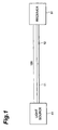
- FIG. 1 is a configurational view of an optical transmission line 100 according to the first embodiment.
- the optical transmission line 100 is configured such that one end of an optical fiber 11 and one end of an optical fiber 12 are connected to each other.
- a light source e.g., semiconductor laser light source
- a receiver e.g., receiver including a photodiode as a light-receiving device
- the optical fibers 11 and 12 can be connected to each other either by fusion or by way of a connector.
- the signal light emitted from the light source 41 propagates through the optical fiber 11 and then through the optical fiber 12, and reaches the receiver 51 so as to be received thereby.
- the effective area of the front-end optical fiber 11 is greater than that of the back-end optical fiber 12.
- the effective area of the back-end optical fiber 12 is smaller than that of the front-end optical fiber 11, since the signal light is made incident on and propagates through the optical fiber 12 after its power is lowered to a certain extent when propagating through the optical fiber 11, the optical energy per unit area in the optical fiber 12 is also small, thus reducing the deterioration in its optical transmission characteristics caused by the occurrence of nonlinear optical phenomena after all.
- the whole optical transmission line 100 in which the optical fibers 11 and 12 are cascaded to each other the deterioration in its optical transmission characteristics caused by the occurrence of nonlinear optical phenomena is lowered.
- the dispersion slope of the front-end optical fiber 11 is greater than that of the back-end optical fiber 12. Namely, though the dispersion slope of the optical fiber 11 must be made greater due to its enhanced effective area, the dispersion slope of the optical fiber 12 can be made smaller since its effective area is smaller than that of the optical fiber 11.
- the dispersion slope of the whole optical transmission line 100, in which the optical fibers 11 and 12 are cascaded to each other, is the weighted mean value of the respective dispersion slopes of the optical fibers 11 and 12 in terms of their lengths, thus being smaller than the dispersion slope of the optical transmission line made of the optical fiber 11 alone.
- the optical fiber 12 contributes to lowering the dispersion slope of the whole optical transmission line 100. Specifically, it is preferred that the dispersion slope of the whole optical transmission line 100 be not greater than 90% of that of the front-end optical fiber 11. The same is true with wavelength dispersion.
- the dispersion slope of the optical fiber 12 is not greater than 1/2 that of the optical fiber 11. In this case, the dispersion slope of the whole optical transmission line 100 can be sufficiently decreased.
- the absolute value of wavelength-dispersion of the whole transmission line 100 is not greater than 5 ps/nm/km. In this case the wavelength dispersion of the whole optical transmission line 100 can be sufficiently reduced, thus allowing the deterioration in its optical transmission characteristics caused by wavelength dispersion to sufficiently decrease. More preferably, the absolute value of wavelength in each of the optical fibers 11 and 12 is not greater than 5 ps/nm/km.
- optical transmission line 100 can suppress influence of the deterioration in its optical transmission characteristics caused by each of the occurrence of nonlinear optical phenomena and the wavelength dispersion, and allow the signal light emitted from the light source 41 to reach the receiver 51.
- both effective area and dispersion slope are greater in the optical fiber 11 than in the optical fiber 12.
- the dispersion slope of the whole optical transmission line 100 is the weighted mean value of the respective dispersion slopes of the optical fibers 11 and 12 in terms of their lengths
- the wavelength dispersion of the whole optical transmission line 100 is the weighted mean value of the respective wavelength dispersions of the optical fibers 11 and 12 in terms of their lengths. Accordingly, the deterioration in its optical transmission characteristics in the whole optical transmission line 100 caused by wavelength dispersion has been reduced as compared with the case where the optical transmission line is made of the optical fiber 11 alone.
- the dispersion slope of the optical fiber 12 is not greater than 1/2 that of the optical fiber 11.
- the absolute value of wavelength dispersion in each of the optical fibers 11 and 12 is not greater than 5 ps/nm/km.
- the dispersion slope of the whole optical transmission line is not greater than 90% of the dispersion slope of the optical fiber 11, from which it can be seen that the optical fiber 12 contributes to lowering the dispersion slope of the whole optical transmission line.
- the transmission loss in the front-end optical fiber 11 is 0.20 dB/km, whereby the power of the signal light transmitted through 30 km of the optical fiber 11 decreases by 6 dB. Accordingly, when the signal light propagates through the optical fiber 11 even with a high power, the deterioration in its optical transmission characteristics caused by the occurrence of nonlinear optical phenomena is reduced since the optical fiber 11 has a large effective area. On the other hand, when the signal light propagates through the optical fiber 12, though it has a small core cross-sectional area, the deterioration in its optical transmission characteristics caused by the occurrence of nonlinear optical phenomena is reduced since the power of the signal light is low. As a result, it has been confirmed that the deterioration in its optical transmission characteristics caused by the occurrence of nonlinear optical phenomena is small in the optical transmission line 100 as a whole.
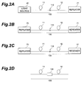
- the optical transmission line 100 according to the first embodiment is not necessarily disposed between the light source 41 and the receiver 51. Similar effects can also be obtained when the optical transmission line 100 is disposed between the light source 41 and a repeater 71 such as optical amplifier as shown in Fig. 2A, between repeaters 71 as shown in Fig. 2B, or between the repeater 71 and the receiver 51 as shown in Fig. 2C.
- a repeater 71 such as optical amplifier as shown in Fig. 2A, between repeaters 71 as shown in Fig. 2B, or between the repeater 71 and the receiver 51 as shown in Fig. 2C.
- the optical fibers 11 and 12 can be connected to each other either by fusion or by way of a connector.
- FIG. 3 is a configurational view of an optical transmission line 200 according to the second embodiment.
- the optical transmission line 200 is configured such that optical fibers 21, 22, and 23 are cascaded to each other in this order.
- a light source 42 for emitting signal light.
- a receiver 52 for receiving the signal light.
- the optical fibers 21 to 23 can be connected to each other either by fusion or by way of a connector.
- the signal light emitted from the light source 42 successively propagates through the optical fibers 21, 22, and 23, and reaches the receiver 52 so as to be received thereby.
- the respective effective areas of the optical fibers 21, 22, and 23 decrease in this order.
- the optical energy of the signal light per unit volume becomes smaller due to the large effective area of the optical fiber 21, thus reducing the deterioration in its optical transmission characteristics caused by the occurrence of nonlinear optical phenomena.
- the effective area of the next-stage optical fiber 22 is smaller than that of the optical fiber 21, since the signal light propagates through the optical fiber 22 after its power is lowered to a certain extent when propagating through the optical fiber 21, the optical energy per unit area in the optical fiber 22 is also small, thus reducing the deterioration in its optical transmission characteristics caused by the occurrence of nonlinear optical phenomena as well.
- the effective area of the back-end optical fiber 23 is smaller than that of the optical fiber 22, since the signal light propagates through the optical fiber 23 after its power is further lowered, the optical energy per unit area in the optical fiber 23 is also small, thus reducing the deterioration in its optical transmission characteristics caused by the occurrence of nonlinear optical phenomena after all.
- the deterioration in its optical transmission characteristics caused by the occurrence of nonlinear optical phenomena is lowered.
- the respective dispersion slopes of the optical fibers 21, 22, and 23 decrease in this order. Namely, though the dispersion slope of the optical fiber 21 must be made greater due to its enhanced effective area, the dispersion slope of the optical fiber 22 can be made smaller since its effective area is smaller than that of the optical fiber 21. The dispersion slope of the optical fiber 23 can be further lowered.
- the dispersion slope of the whole optical transmission line 200 is the weighted mean value of the respective dispersion slopes of the optical fibers 21 to 23 in terms of their lengths, thus being smaller than the dispersion slope of the optical transmission line made of the optical fiber 21 alone.
- the optical fibers 22 and 23 contribute to lowering the dispersion slope of the whole optical transmission line 200.
- the dispersion slope of the whole optical transmission line 200 be not greater than 90% of that of the optical fiber 21. The same is true with wavelength dispersion.
- optical transmission line 200 can suppress influence of the deterioration in its optical transmission characteristics caused by each of the occurrence of nonlinear optical phenomena and the wavelength dispersion, and allow the signal light emitted from the light source 42 to reach the receiver 52. Further, since the optical transmission line 200 according to the second embodiment is configured such that the effective areas and dispersion slopes of the respective optical fibers 21 and 23 are changed stepwise by way of the optical fiber 21, at each of the connecting point between the optical fibers 21 and 22 and the connecting point between the optical fibers 22 and 23 can be reduced, which results in a reduction of the connection loss as the whole optical transmission line.
- the dispersion slope of the whole optical transmission line 200 is the weighted mean value of the respective dispersion slopes of the optical fibers 21 to 23 in terms of their lengths
- the wavelength dispersion of the whole optical transmission line 200 is the weighted mean value of the respective wavelength dispersions of the optical fibers 21 to 23 in terms of their lengths. Accordingly, the deterioration in its optical transmission characteristics in the whole optical transmission line 200 caused by wavelength dispersion has been reduced as compared with the case where the optical transmission line is made of the optical fiber 21 alone.
- the absolute value of wavelength dispersion in each of the optical fibers 21, 22, and 23 is not greater than 5 ps/nm/km.
- the transmission loss in the front-end optical fiber 21 is 0.20 dB/km, whereby the power of the signal light transmitted through 10 km of the optical fiber 21 decreases by 2 dB.
- the transmission loss in the next-stage optical fiber 21 is also 0.20 dB/km, whereby the power of the signal light transmitted through 20 km of the optical fiber 22 further decreases by 4 dB. Accordingly, when the signal light propagates through the optical fiber 21 even with a high power, the deterioration in its optical transmission characteristics caused by the occurrence of nonlinear optical phenomena is reduced since the optical fiber 21 has a large effective area.
- the deterioration in its optical transmission characteristics caused by the occurrence of nonlinear optical phenomena is reduced since the power of the signal light is low.
- the signal light propagates through the optical fiber 23, though its effective area is smaller, the deterioration in its optical transmission characteristics caused by the occurrence of nonlinear optical phenomena is reduced since the power of the signal light is lower. Also, it has been confirmed that the deterioration in its optical transmission characteristics caused by the occurrence of nonlinear optical phenomena is small in the optical transmission line 200 as a whole.
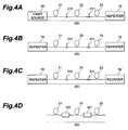
- the optical transmission line 200 according to the second embodiment is not necessarily disposed between the light source 42 and the receiver 52. Similar effects can also be obtained when the optical transmission line 200 is disposed between the light source 42 and a repeater 72 such as optical amplifier as shown in Fig. 4A, between repeaters 72 as shown in Fig. 4B, or between the repeater 72 and the receiver 52 as shown in Fig. 4C.
- a repeater 72 such as optical amplifier as shown in Fig. 4A, between repeaters 72 as shown in Fig. 4B, or between the repeater 72 and the receiver 52 as shown in Fig. 4C.
- the optical fibers 21, 22, and 23 can be connected to each other either by fusion or by way of a connector.
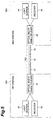
- FIG. 5 is a configurational view of an optical transmission line 300 according to the third embodiment.
- the optical transmission line 300 is configured such that optical fibers 31, 32, and 33 are cascaded to each other in this order.
- Connected to the free end of the optical fiber 31 by way of an optical multi/demultiplexer 61 are a light source 43 and a receiver 53.
- Connected to the free end of the optical fiber 33 by way of an optical multi/demultiplexer 62 are a light source 44 and a receiver 54.
- the optical fibers 31 to 33 can be connected to each other either by fusion or by way of a connector.
- the light source 43, receiver 53, and optical multi/demultiplexer 61 constitute a first station 500
- the light source 44, receiver 54, and optical multi/demultiplexer 62 constitute a second station 600.
- the optical transmission line 300 has a configuration for enabling bidirectional optical communications.
- the signal light emitted from the light source 43, by way of the optical multi/demultiplexer 61 successively propagates through the optical fibers 31, 32, and 33, and then is, by way of the multi/demultiplexer 62, received by the receiver 54.
- the signal light emitted from the light source 44, by way of the optical multi/demultiplexer 62 successively propagates through the optical fibers 33, 32, and 31, and then is, by way of the multi/demultiplexer 61, received by the receiver 53.
- the effective area of each of the optical fibers 31 and 33 is larger than the effective area of the optical fiber 32.
- the effective area of the next-stage optical fiber 32 is smaller than that of the optical fiber 31, since the signal light propagates through the optical fiber 32 after its power is lowered to a certain extent when propagating through the optical fiber 31, the optical energy per unit area in the optical fiber 32 is also small, thus reducing the deterioration in its optical transmission characteristics caused by the occurrence of nonlinear optical phenomena as well. Since the signal light propagates through the optical fiber 33 after its power is further lowered, the optical energy per unit area in the optical fiber 33 is small, thus reducing the deterioration in its optical transmission characteristics caused by the occurrence of nonlinear optical phenomena as well. The same is true with the case where the signal light emitted from the light source 44 propagates to the receiver 53.
- the dispersion slope of each of the optical fibers 31 and 33 is greater than the dispersion slope of the optical fiber 32. Namely, though the dispersion slope of each of the optical fibers 31 and 33 must be made greater due to their enhanced effective area, the dispersion slope of the optical fiber 32 can be made smaller since its effective area is smaller than that of each of the optical fibers 31 and 33.
- the dispersion slope of the whole optical transmission line 300 is the weighted mean value of the respective dispersion slopes of the optical fibers 31 to 33 in terms of their lengths, thus being smaller than the dispersion slope of the optical transmission line made of the optical fiber 31 or 33 alone.
- the optical fiber 32 contributes to lowering the dispersion slope of the whole optical transmission line 300.
- the dispersion slope of the whole optical transmission line 300 be not greater than 90% of that of the optical fiber 31 or 33. The same is true with wavelength dispersion.
- optical transmission line 300 can suppress influence of the deterioration in its optical transmission characteristics caused by each of the occurrence of nonlinear optical phenomena and the wavelength dispersion. Further, since the deterioration in its optical transmission characteristics can be reduced in the signal light propagating in either direction, the optical transmission line 300 according to the third embodiment is suitably used for bidirectional communications.
- the optical fibers 31 and 33 have an identical effective area and an identical dispersion slope, which are respectively greater than the effective area and dispersion slope of the optical fiber 32.
- the dispersion slope of the whole optical transmission line 300 is the weighted mean value of the respective dispersion slopes of the optical fibers 31 to 33 in terms of their lengths
- the wavelength dispersion of the whole optical transmission line 300 is the weighted mean value of the respective wavelength dispersions of the optical fibers 31 to 33 in terms of their lengths. Accordingly, the deterioration in its optical transmission characteristics in the whole optical transmission line 300 caused by wavelength dispersion has been reduced as compared with the case where the optical transmission line is made of the optical fiber 31 or 33 alone.
- the absolute value of wavelength dispersion in each of the optical fibers 31, 32, and 33 is not greater than 5 ps/nm/km.
- the transmission loss in the front-end optical fiber 31 is 0.20 dB/km, whereby the power of the signal light transmitted through 30 km of the optical fiber 31 decreases by 6 dB.
- the transmission loss in the optical fiber 32 is also 0.20 dB/km, whereby the power of the signal light transmitted through 30 km of the optical fiber 32 further decreases by 6 dB. Accordingly, when the signal light emitted from the light source 43 propagates through the optical fiber 31 even with a high power, the deterioration in its optical transmission characteristics caused by the occurrence of nonlinear optical phenomena is reduced since the optical fiber 31 has a large effective area.
- the deterioration in its optical transmission characteristics caused by the occurrence of nonlinear optical phenomena is reduced since the power of the signal light is low.
- the signal light propagates through the optical fiber 33 since its effective area is large, and the power of the signal light is further lower, the deterioration in its optical transmission characteristics caused by the occurrence of nonlinear optical phenomena is reduced.
- the deterioration in its optical transmission characteristics caused by the occurrence of nonlinear optical phenomena is small in the optical transmission line 300 as a whole.
- the deterioration in its optical transmission characteristics caused by the occurrence of nonlinear optical phenomena is small when the signal light emitted from the light source 44 propagates to the receiver 53.
- the optical transmission line 300 according to the third embodiment is not necessarily disposed between the first station 500 including the light source 43, receiver 53, and the like and the second station 600 including the light source 44, receiver 54, and the like. Similar effects can also be obtained when the optical transmission line 300 is disposed between the first station 500 and a repeater 73 such as optical amplifier as shown in Fig. 6A, between repeaters 73 as shown in Fig. 6B, or between the repeater 73 and the second station 600 as shown in Fig. 6C.
- a repeater 73 such as optical amplifier as shown in Fig. 6A, between repeaters 73 as shown in Fig. 6B, or between the repeater 73 and the second station 600 as shown in Fig. 6C.
- the optical fibers 31, 32, and 33 can be connected to each other either by fusion or by way of a connector.
- the number of optical fibers constituting the optical transmission line 200 is 3 in the second embodiment, a larger number of optical fibers can be cascaded to each other. Also in this case, the optical fiber having a larger effective area and a greater dispersion slope is connected closer to the light source.
- the present invention even when the signal light propagating through the first optical fiber has a high power, the deterioration in its optical transmission characteristics caused by the occurrence of nonlinear optical phenomena is reduced since the first effective area is large. Also, since the signal light propagating through the second optical fiber after propagating through the first optical fiber lowers its power when propagating through the first optical fiber, the deterioration in its optical transmission characteristics caused by the occurrence of nonlinear optical phenomena is reduced even though the second effective area is small. Accordingly, the deterioration in its optical transmission characteristics caused by the occurrence of nonlinear optical phenomena is also reduced in the optical transmission line as a whole.
- the dispersion slope of the whole optical transmission line is the weighted mean value of the first and second dispersion slopes in terms of length, it is smaller than in the case where the first optical fiber is used alone. Consequently, the deterioration in its optical transmission characteristics caused by wavelength dispersion is also lowered.
- the dispersion slope of the whole optical transmission line sufficiently decreases.
- the first, second, and third optical fibers are cascaded to each other in this order. Accordingly, the deterioration in its optical transmission characteristics caused by each of the occurrence of nonlinear optical phenomena and the wavelength dispersion is reduced not only in the signal light propagating from the first optical fiber to the third optical fiber but also in the signal light propagating from the third optical fiber to the first optical fiber.
- the effective areas and dispersion slopes of the predetermined number of cascaded optical fibers are configured so as to change stepwise, structural dissociation of optical fibers at each optical fiber connecting point can be reduced, thereby allowing the connection loss in the whole optical transmission line to decrease.
- each of the optical fibers constituting the optical transmission line has a wavelength dispersion whose absolute value is not greater than 5 ps/nm/km.
- the optical transmission line according to the present invention dispersion slope is greater in the optical fiber having a larger effective area, whereas it is smaller in the optical fiber having a smaller effective area. Accordingly, each of the optical fibers constituting the optical transmission line can be designed and manufactured easily. Namely, the optical transmission line capable of suppressing the deterioration in its optical transmission characteristics caused by each of the occurrence of nonlinear optical phenomena and the wavelength dispersion can be constructed inexpensively. Accordingly, the optical transmission line according to the present invention is suitably used for large-capacity long-haul communications by means of WDM transmission.
Landscapes
- Physics & Mathematics (AREA)
- Electromagnetism (AREA)
- Engineering & Computer Science (AREA)
- Computer Networks & Wireless Communication (AREA)
- Signal Processing (AREA)
- Optical Communication System (AREA)
- Optical Fibers, Optical Fiber Cores, And Optical Fiber Bundles (AREA)
- Light Guides In General And Applications Therefor (AREA)
Abstract
Description


Claims (24)
- An optical transmission line comprising:a first optical fiber having, as characteristics at a predetermined operating wavelength, a first effective area and a first dispersion slope; anda second optical fiber optically connected to said first optical fiber so as to let in the signal light that has propagated through said first optical fiber, said second optical fiber having, as characteristics at the predetermined operating wavelength, a second effective area smaller than said first effective area and a second dispersion slope smaller than said first dispersion slope.
- An optical transmission line according to claim 1, wherein said second dispersion slope is not greater than 1/2 of said first dispersion slope.
- An optical transmission line according to claim 1, wherein said first and second optical fibers each have a wavelength dispersion whose absolute value is not greater than 5 ps/nm/km at the predetermined operating wavelength.
- An optical transmission line according to claim 1, wherein said optical transmission line as a whole has a wavelength dispersion whose absolute value is not greater than 5 ps/nm/km at the predetermined operating wavelength.
- An optical transmission line according to claim 1, wherein the signal light incident on said first optical fiber has a power higher than the signal light incident on said second optical fiber.
- An optical transmission line according to claim 1, wherein said second optical fiber functions such that said optical transmission line as a whole has a dispersion slope at the predetermined operating wavelength smaller than said first dispersion slope.
- An optical transmission line according to claim 1, wherein said optical transmission line has a dispersion slope not greater than 90% of said first dispersion slope.
- An optical transmission line according to claim 1, wherein said optical transmission line is disposed, at least, between a light source and a receiver, between a light source and a repeater, between repeaters, or between a repeater and a receiver.
- An optical transmission line according to claim 1, further comprising:a third optical fiber optically connected to said second optical fiber so as to let in said signal light that has propagated through said second optical fiber, said third optical fiber having, as characteristics at the predetermined operating wavelength, a third effective area larger than said second effective area and a third dispersion slope greater than said second dispersion slope.
- An optical transmission line according to claim 9, wherein said optical transmission line is disposed, at least, between first and second stations each including a light source and a receiver, between the first station and a repeater, between repeaters, or between a repeater and the second station.
- An optical transmission line comprising a plurality of optical fibers disposed along a propagating direction of signal light;
wherein a first optical fiber of a pair of optical fibers selected from said plurality of optical fibers has, as characteristics at a predetermined operating wavelength, a first effective area and a first dispersion slope; and
wherein a second optical fiber of the pair of optical fibers selected from said plurality of optical fibers is disposed so as to let in the signal light that has propagated through said first optical fiber, said second optical fiber having, as characteristics at the predetermined operating wavelength, a second effective area smaller than said first effective area and a second dispersion slope smaller than said first dispersion slope. - An optical transmission line according to claim 11, wherein said plurality of optical fibers each have a wavelength dispersion whose absolute value is not greater than 5 ps/nm/km at the predetermined operating wavelength.
- An optical transmission line according to claim 11, wherein said optical transmission line as a whole has a wavelength dispersion whose absolute value is not greater than 5 ps/nm/km at the predetermined operating wavelength.
- An optical transmission line comprising:a first optical fiber having, as characteristics at a predetermined operating wavelength, a first effective area, a first dispersion slope, and a wavelength dispersion whose absolute value is not greater than 5 ps/nm/km; anda second optical fiber optically connected to said first optical fiber so as to let in the signal light that has propagated through said first optical fiber, said second optical fiber having, as characteristics at the predetermined operating wavelength, a second effective area smaller than said first effective area, a second dispersion slope smaller than said first dispersion slope, and a wavelength dispersion whose absolute value is not greater than 5 ps/nm/km.
- An optical transmission line according to claim 14, wherein said second dispersion slope is not greater than 1/2 of said first dispersion slope.
- An optical transmission line according to claim 14, wherein said optical transmission line as a whole has a wavelength dispersion whose absolute value is not greater than 5 ps/nm/km at the predetermined operating wavelength.
- An optical transmission line according to claim 14, wherein the signal light incident on said first optical fiber has a power higher than the signal light incident on said second optical fiber.
- An optical transmission line according to claim 14, wherein said second optical fiber functions such that said optical transmission line as a whole has a dispersion slope at the predetermined operating wavelength smaller than said first dispersion slope.
- An optical transmission line according to claim 14, wherein said optical transmission line has a dispersion slope not greater than 90% of said first dispersion slope.
- An optical transmission line according to claim 14, wherein said optical transmission line is disposed, at least, between a light source and a receiver, between a light source and a repeater, between repeaters, or between a repeater and a receiver.
- An optical transmission line according to claim 14, further comprising:a third optical fiber optically connected to said second optical fiber so as to let in said signal light that has propagated through said second optical fiber, said third optical fiber having, as characteristics at the predetermined operating wavelength, a third effective area larger than said second effective area, a third dispersion slope greater than said second dispersion slope, and a wavelength dispersion whose absolute value is not greater than 5 ps/nm/km.
- An optical transmission line according to claim 21, wherein said optical transmission line is disposed, at least, between first and second stations each including a light source and a receiver, between the first station and a repeater, between repeaters, or between a repeater and the second station.
- An optical transmission line according to claim 14, further comprising:a third optical fiber optically connected to said second optical fiber so as to let in said signal light that has propagated through said second optical fiber, said third optical fiber having, as characteristics at the predetermined operating wavelength, a third effective area smaller than said second effective area, a third dispersion slope smaller than said second dispersion slope, and a wavelength dispersion whose absolute value is not greater than 5 ps/nm/km.
- An optical transmission line according to claim 23, wherein said optical transmission line is disposed, at least, between a light source and a receiver, between a light source and a repeater, between repeaters, or between a repeater and a receiver.
Applications Claiming Priority (3)
| Application Number | Priority Date | Filing Date | Title |
|---|---|---|---|
| JP11971097 | 1997-05-09 | ||
| JP11971097A JP3418086B2 (en) | 1997-05-09 | 1997-05-09 | Optical transmission line for wavelength division multiplexing transmission and method of configuring the same |
| JP119710/97 | 1997-05-09 |
Publications (3)
| Publication Number | Publication Date |
|---|---|
| EP0877496A2 true EP0877496A2 (en) | 1998-11-11 |
| EP0877496A3 EP0877496A3 (en) | 2000-03-08 |
| EP0877496B1 EP0877496B1 (en) | 2002-02-27 |
Family
ID=14768193
Family Applications (1)
| Application Number | Title | Priority Date | Filing Date |
|---|---|---|---|
| EP98108440A Expired - Lifetime EP0877496B1 (en) | 1997-05-09 | 1998-05-08 | Optical transmission line with reduction of the wavelength dispersion distortion |
Country Status (8)
| Country | Link |
|---|---|
| US (1) | US6157754A (en) |
| EP (1) | EP0877496B1 (en) |
| JP (1) | JP3418086B2 (en) |
| KR (1) | KR100321391B1 (en) |
| CN (1) | CN1106090C (en) |
| AU (1) | AU762657C (en) |
| CA (1) | CA2237085C (en) |
| DE (1) | DE69803954T2 (en) |
Cited By (12)
| Publication number | Priority date | Publication date | Assignee | Title |
|---|---|---|---|---|
| FR2788180A1 (en) * | 1999-01-04 | 2000-07-07 | Cit Alcatel | WAVELENGTH MULTIPLEXED FIBER OPTIC TRANSMISSION SYSTEM |
| WO2000049742A1 (en) * | 1999-02-18 | 2000-08-24 | Fujitsu Limited | Optical fiber transmission line for wavelength division multiplexing transmission system |
| WO2000054439A1 (en) * | 1999-03-09 | 2000-09-14 | Sumitomo Electric Industries, Ltd. | Optical communication system |
| DE19961514A1 (en) * | 1999-12-20 | 2001-06-21 | Siemens Ag | Arrangement to reduce stimulated Brillouin scatter in optical fibre cable |
| EP1130824A2 (en) * | 2000-02-25 | 2001-09-05 | DDI Corporation | Optical transmission line with Raman amplification |
| WO2002042815A2 (en) * | 2000-11-27 | 2002-05-30 | Nortel Networks Limited | Dispersion managed optical fiber and system |
| WO2002048771A2 (en) * | 2000-12-12 | 2002-06-20 | Ccs Technology, Inc | Optical-fiber cable and method for transmitting optical signals, particularly according to wavelength multiplexing technology |
| WO2002019576A3 (en) * | 2000-08-31 | 2002-06-20 | Pirelli Cavi E Sistemi Spa | Optical transmission link with low slope, raman amplified fiber |
| WO2002052756A1 (en) * | 2000-12-26 | 2002-07-04 | Nortel Networks Limited | Method and apparatus for reducing dispersion slope in optical transmission fibre systems |
| EP1278316A1 (en) * | 2000-03-13 | 2003-01-22 | Sumitomo Electric Industries, Ltd. | Dispersion compensator |
| US6941054B2 (en) | 2000-08-31 | 2005-09-06 | Pirelli S.P.A. | Optical transmission link with low slope, raman amplified fiber |
| CN1351428B (en) * | 2000-10-30 | 2011-06-22 | 富士通株式会社 | Distributive optical amplifier, optical communication station, system and cables |
Families Citing this family (22)
| Publication number | Priority date | Publication date | Assignee | Title |
|---|---|---|---|---|
| JP3682374B2 (en) * | 1998-07-07 | 2005-08-10 | 古河電気工業株式会社 | Optical fiber type optical components |
| JP4240612B2 (en) * | 1998-12-02 | 2009-03-18 | 住友電気工業株式会社 | Dispersion compensation module |
| US6853766B2 (en) * | 1998-12-02 | 2005-02-08 | Sumitomo Electric Industries, Ltd. | Dispersion-compensating module |
| FR2790105B1 (en) * | 1999-02-18 | 2003-07-04 | Cit Alcatel | FIBER OPTIC TRANSMISSION SYSTEM, LINE AND METHOD |
| KR20010043972A (en) * | 1999-04-01 | 2001-05-25 | 오카야마 노리오 | WDM optical communication system |
| FR2801685B1 (en) * | 1999-11-25 | 2002-02-22 | Cit Alcatel | OPTICAL FIBER WITH OFFSET CHROMATIC DISPERSION FOR WAVELENGTH MULTIPLEXED FIBER OPTIC TRANSMISSION SYSTEMS |
| US6628872B2 (en) | 2000-03-13 | 2003-09-30 | Sumitomo Electric Industries, Ltd. | Dispersion compensator and optical transmission system |
| US6633712B2 (en) | 2001-03-16 | 2003-10-14 | Sowilo Networks, Inc. | Method and system for dispersion maps and enhanced distributed gain effect in long haul telecommunications |
| US6694081B2 (en) | 2001-04-12 | 2004-02-17 | Corning Incorporated | Dispersion managed cable for WDM systems |
| EP1326354A3 (en) | 2001-12-07 | 2005-07-20 | Sumitomo Electric Industries, Ltd. | Optical fiber transmission line, optical cable, and optical transmission system |
| US6687443B2 (en) | 2001-12-07 | 2004-02-03 | Sumitomo Electric Industries, Ltd. | Optical fiber transmission line, optical cable, and optical transmission system |
| US6934570B2 (en) * | 2002-01-08 | 2005-08-23 | Masimo Corporation | Physiological sensor combination |
| JP3985571B2 (en) * | 2002-04-08 | 2007-10-03 | 住友電気工業株式会社 | Optical demultiplexer and optical transmission system |
| US6785456B2 (en) * | 2002-04-12 | 2004-08-31 | Corning Incorporated | Dispersion managed cable for unrepeatered systems |
| US20040037568A1 (en) * | 2002-08-20 | 2004-02-26 | Evangelides Stephen G. | Optical repeater employed in an optical communication system having a modular dispersion map |
| US20040096223A1 (en) * | 2002-08-20 | 2004-05-20 | Red Sky Systems, Inc. | Modular dispersion map for an optical communication system |
| JP4172315B2 (en) * | 2003-04-22 | 2008-10-29 | 住友電気工業株式会社 | Optical transmission line and optical transmission system |
| US6993228B2 (en) * | 2003-08-13 | 2006-01-31 | Corning Incorporated | Dispersion compensated optical fiber transmission system and module including micro-structured optical fiber |
| WO2008044600A1 (en) * | 2006-10-04 | 2008-04-17 | The Furukawa Electric Co., Ltd. | Optical fiber and optical fiber transmission path |
| JP4974161B2 (en) * | 2007-07-27 | 2012-07-11 | 古河電気工業株式会社 | Optical fiber device |
| US7869673B2 (en) * | 2008-08-29 | 2011-01-11 | Xtera Communications, Inc. | Remote larger effective area optical fiber |
| US8538218B2 (en) * | 2010-03-10 | 2013-09-17 | Corning Incorporated | Unrepeatered long haul optical fiber transmission systems |
Citations (2)
| Publication number | Priority date | Publication date | Assignee | Title |
|---|---|---|---|---|
| US5191631A (en) * | 1991-12-19 | 1993-03-02 | At&T Bell Laboratories | Hybrid optical fiber and method of increasing the effective area of optical transmission using same |
| EP0790510A2 (en) * | 1996-02-16 | 1997-08-20 | Corning Incorporated | A symmetric, dispersion-manager fiber optic cable and system |
Family Cites Families (8)
| Publication number | Priority date | Publication date | Assignee | Title |
|---|---|---|---|---|
| JPH0884135A (en) * | 1994-09-13 | 1996-03-26 | Furukawa Electric Co Ltd:The | Wavelength multiplexed optical communication system |
| US5613027A (en) * | 1994-10-17 | 1997-03-18 | Corning Incorporated | Dispersion shifted optical waveguide fiber |
| US5835655A (en) * | 1995-01-26 | 1998-11-10 | Corning Incorporated | Large effective area waveguide fiber |
| JPH08331049A (en) * | 1995-03-27 | 1996-12-13 | Hitachi Cable Ltd | Long distance optical transmission system |
| JPH0923187A (en) * | 1995-07-10 | 1997-01-21 | Fujitsu Ltd | Optical transmission system |
| JP3474982B2 (en) * | 1995-10-24 | 2003-12-08 | 株式会社日立製作所 | Optical fiber communication system |
| US5737460A (en) * | 1995-12-29 | 1998-04-07 | Lucent Technologies Inc. | Applications of solitons in transmission systems employing high launch powers |
| US5781673A (en) * | 1997-02-05 | 1998-07-14 | Lucent Technologies Inc. | WDM optical fiber communication system with improved dispersion compensation |
-
1997
- 1997-05-09 JP JP11971097A patent/JP3418086B2/en not_active Expired - Fee Related
-
1998
- 1998-05-07 AU AU64769/98A patent/AU762657C/en not_active Ceased
- 1998-05-07 CA CA002237085A patent/CA2237085C/en not_active Expired - Fee Related
- 1998-05-08 KR KR1019980016394A patent/KR100321391B1/en not_active IP Right Cessation
- 1998-05-08 DE DE69803954T patent/DE69803954T2/en not_active Expired - Fee Related
- 1998-05-08 EP EP98108440A patent/EP0877496B1/en not_active Expired - Lifetime
- 1998-05-08 CN CN98107498A patent/CN1106090C/en not_active Expired - Fee Related
- 1998-05-11 US US09/075,324 patent/US6157754A/en not_active Expired - Lifetime
Patent Citations (2)
| Publication number | Priority date | Publication date | Assignee | Title |
|---|---|---|---|---|
| US5191631A (en) * | 1991-12-19 | 1993-03-02 | At&T Bell Laboratories | Hybrid optical fiber and method of increasing the effective area of optical transmission using same |
| EP0790510A2 (en) * | 1996-02-16 | 1997-08-20 | Corning Incorporated | A symmetric, dispersion-manager fiber optic cable and system |
Non-Patent Citations (1)
| Title |
|---|
| NOUCHI P ET AL: "NEW DISPERSION SHIFTED FIBER WITH EFFECTIVE AREA LARGER THAN 90 MUM2" PROCEEDINGS OF THE EUROPEAN CONFERENCE ON OPTICAL COMMUNICATION, XP000775986 * |
Cited By (20)
| Publication number | Priority date | Publication date | Assignee | Title |
|---|---|---|---|---|
| EP1018812A1 (en) * | 1999-01-04 | 2000-07-12 | Alcatel | Optical fiber WDM transmission system with chromatic dispersion compensation |
| FR2788180A1 (en) * | 1999-01-04 | 2000-07-07 | Cit Alcatel | WAVELENGTH MULTIPLEXED FIBER OPTIC TRANSMISSION SYSTEM |
| WO2000049742A1 (en) * | 1999-02-18 | 2000-08-24 | Fujitsu Limited | Optical fiber transmission line for wavelength division multiplexing transmission system |
| US6480658B1 (en) | 1999-02-18 | 2002-11-12 | Fujitsu Limited | Optical fiber transmission line for wavelength division multiplexing transmission system |
| US6453103B1 (en) | 1999-03-09 | 2002-09-17 | Sumitomo Electric Industries, Ltd. | Optical communication system |
| WO2000054439A1 (en) * | 1999-03-09 | 2000-09-14 | Sumitomo Electric Industries, Ltd. | Optical communication system |
| DE19961514A1 (en) * | 1999-12-20 | 2001-06-21 | Siemens Ag | Arrangement to reduce stimulated Brillouin scatter in optical fibre cable |
| EP1130824A2 (en) * | 2000-02-25 | 2001-09-05 | DDI Corporation | Optical transmission line with Raman amplification |
| EP1130824A3 (en) * | 2000-02-25 | 2004-09-29 | DDI Corporation | Optical transmission line with Raman amplification |
| EP1278316A1 (en) * | 2000-03-13 | 2003-01-22 | Sumitomo Electric Industries, Ltd. | Dispersion compensator |
| EP1278316A4 (en) * | 2000-03-13 | 2006-11-22 | Sumitomo Electric Industries | Dispersion compensator |
| WO2002019576A3 (en) * | 2000-08-31 | 2002-06-20 | Pirelli Cavi E Sistemi Spa | Optical transmission link with low slope, raman amplified fiber |
| US6941054B2 (en) | 2000-08-31 | 2005-09-06 | Pirelli S.P.A. | Optical transmission link with low slope, raman amplified fiber |
| CN1351428B (en) * | 2000-10-30 | 2011-06-22 | 富士通株式会社 | Distributive optical amplifier, optical communication station, system and cables |
| WO2002042815A2 (en) * | 2000-11-27 | 2002-05-30 | Nortel Networks Limited | Dispersion managed optical fiber and system |
| WO2002042815A3 (en) * | 2000-11-27 | 2003-03-13 | Nortel Networks Ltd | Dispersion managed optical fiber and system |
| WO2002048771A2 (en) * | 2000-12-12 | 2002-06-20 | Ccs Technology, Inc | Optical-fiber cable and method for transmitting optical signals, particularly according to wavelength multiplexing technology |
| WO2002048771A3 (en) * | 2000-12-12 | 2003-04-03 | Scc Special Comm Cables Gmbh | Optical-fiber cable and method for transmitting optical signals, particularly according to wavelength multiplexing technology |
| US6856736B2 (en) | 2000-12-12 | 2005-02-15 | Ccs Technology, Inc. | Lightwaveguide cable and process for carrying an optical signal using dispersion management |
| WO2002052756A1 (en) * | 2000-12-26 | 2002-07-04 | Nortel Networks Limited | Method and apparatus for reducing dispersion slope in optical transmission fibre systems |
Also Published As
| Publication number | Publication date |
|---|---|
| JP3418086B2 (en) | 2003-06-16 |
| CN1199290A (en) | 1998-11-18 |
| US6157754A (en) | 2000-12-05 |
| DE69803954T2 (en) | 2002-10-10 |
| JPH10308706A (en) | 1998-11-17 |
| EP0877496A3 (en) | 2000-03-08 |
| AU762657C (en) | 2004-08-05 |
| CA2237085C (en) | 2002-09-17 |
| EP0877496B1 (en) | 2002-02-27 |
| AU762657B2 (en) | 2003-07-03 |
| DE69803954D1 (en) | 2002-04-04 |
| CA2237085A1 (en) | 1998-11-09 |
| CN1106090C (en) | 2003-04-16 |
| KR19980086850A (en) | 1998-12-05 |
| KR100321391B1 (en) | 2002-03-08 |
| AU6476998A (en) | 1998-11-12 |
Similar Documents
| Publication | Publication Date | Title |
|---|---|---|
| US6157754A (en) | Optical transmission line | |
| US6859597B2 (en) | Index-guiding microstructured optical fibers | |
| AU745736B2 (en) | Dispersion equalization optical fiber and optical transmission line including the same | |
| JP3893877B2 (en) | Dispersion compensating fiber | |
| EP0862069A2 (en) | Optical fiber | |
| US6477306B2 (en) | Dispersion-compensating optical fiber, and, optical transmission line and dispersion-compensating module respectively including the same | |
| US6603913B1 (en) | Single-mode optical fiber having multiple cladding regions for dispersion compensation | |
| US6556758B2 (en) | Optical fiber and optical transmission line including the same | |
| US6256440B1 (en) | Dispersion-shifted optical fiber | |
| US20020168160A1 (en) | Optical transmission line, and optical fiber and dispersion compensating module employed in the same | |
| US6611637B1 (en) | Dispersion-compensating module | |
| US7164829B2 (en) | Optical fiber, optical transmission line and optical communications system | |
| US20030108315A1 (en) | Optical fiber transmission line, optical cable, and optical transmission system | |
| CA2430007A1 (en) | Dispersion managed optical fiber and system | |
| US7085463B2 (en) | Optical fiber and optical transmission line | |
| US7194171B2 (en) | Dispersion compensating optical fiber, dispersion compensating device, optical transmission line and optical transmission system | |
| US6687443B2 (en) | Optical fiber transmission line, optical cable, and optical transmission system | |
| US20030169986A1 (en) | Optical fiber, optical component, dispersion compensating fiber module, and optical communication system | |
| JPH1117624A (en) | Optical transmission line | |
| US6684017B1 (en) | Optical transmission line and optical transmission system including the same | |
| US20060257085A1 (en) | Fiberoptics, fiberoptic transmission line and optical transmission system | |
| Hatayama et al. | The Investigation of Proper Dispersion Characteristics for Dispersion Compensation-free 10Gb/s Systems by Analytical Calculations | |
| JP2004037503A (en) | Optical fiber |
Legal Events
| Date | Code | Title | Description |
|---|---|---|---|
| PUAI | Public reference made under article 153(3) epc to a published international application that has entered the european phase |
Free format text: ORIGINAL CODE: 0009012 |
|
| AK | Designated contracting states |
Kind code of ref document: A2 Designated state(s): DE FR GB IT |
|
| AX | Request for extension of the european patent |
Free format text: AL;LT;LV;MK;RO;SI |
|
| 17P | Request for examination filed |
Effective date: 19990719 |
|
| PUAL | Search report despatched |
Free format text: ORIGINAL CODE: 0009013 |
|
| AK | Designated contracting states |
Kind code of ref document: A3 Designated state(s): AT BE CH CY DE DK ES FI FR GB GR IE IT LI LU MC NL PT SE |
|
| AX | Request for extension of the european patent |
Free format text: AL;LT;LV;MK;RO;SI |
|
| 17Q | First examination report despatched |
Effective date: 20000526 |
|
| AKX | Designation fees paid |
Free format text: DE FR GB IT |
|
| GRAG | Despatch of communication of intention to grant |
Free format text: ORIGINAL CODE: EPIDOS AGRA |
|
| GRAG | Despatch of communication of intention to grant |
Free format text: ORIGINAL CODE: EPIDOS AGRA |
|
| GRAH | Despatch of communication of intention to grant a patent |
Free format text: ORIGINAL CODE: EPIDOS IGRA |
|
| GRAH | Despatch of communication of intention to grant a patent |
Free format text: ORIGINAL CODE: EPIDOS IGRA |
|
| REG | Reference to a national code |
Ref country code: GB Ref legal event code: IF02 |
|
| GRAA | (expected) grant |
Free format text: ORIGINAL CODE: 0009210 |
|
| AK | Designated contracting states |
Kind code of ref document: B1 Designated state(s): DE FR GB IT |
|
| REF | Corresponds to: |
Ref document number: 69803954 Country of ref document: DE Date of ref document: 20020404 |
|
| ET | Fr: translation filed | ||
| PLBE | No opposition filed within time limit |
Free format text: ORIGINAL CODE: 0009261 |
|
| STAA | Information on the status of an ep patent application or granted ep patent |
Free format text: STATUS: NO OPPOSITION FILED WITHIN TIME LIMIT |
|
| 26N | No opposition filed |
Effective date: 20021128 |
|
| PGFP | Annual fee paid to national office [announced via postgrant information from national office to epo] |
Ref country code: GB Payment date: 20050504 Year of fee payment: 8 |
|
| PGFP | Annual fee paid to national office [announced via postgrant information from national office to epo] |
Ref country code: DE Payment date: 20050506 Year of fee payment: 8 |
|
| PG25 | Lapsed in a contracting state [announced via postgrant information from national office to epo] |
Ref country code: GB Free format text: LAPSE BECAUSE OF NON-PAYMENT OF DUE FEES Effective date: 20060508 |
|
| PGFP | Annual fee paid to national office [announced via postgrant information from national office to epo] |
Ref country code: IT Payment date: 20060531 Year of fee payment: 9 |
|
| PG25 | Lapsed in a contracting state [announced via postgrant information from national office to epo] |
Ref country code: DE Free format text: LAPSE BECAUSE OF NON-PAYMENT OF DUE FEES Effective date: 20061201 |
|
| GBPC | Gb: european patent ceased through non-payment of renewal fee |
Effective date: 20060508 |
|
| PG25 | Lapsed in a contracting state [announced via postgrant information from national office to epo] |
Ref country code: IT Free format text: LAPSE BECAUSE OF NON-PAYMENT OF DUE FEES Effective date: 20070508 |
|
| PGFP | Annual fee paid to national office [announced via postgrant information from national office to epo] |
Ref country code: FR Payment date: 20130531 Year of fee payment: 16 |
|
| REG | Reference to a national code |
Ref country code: FR Ref legal event code: ST Effective date: 20150130 |
|
| PG25 | Lapsed in a contracting state [announced via postgrant information from national office to epo] |
Ref country code: FR Free format text: LAPSE BECAUSE OF NON-PAYMENT OF DUE FEES Effective date: 20140602 |