EP1396297A1 - Tiefziehvorrichtung und Verfahren zum Tiefziehen - Google Patents
Tiefziehvorrichtung und Verfahren zum Tiefziehen Download PDFInfo
- Publication number
- EP1396297A1 EP1396297A1 EP02020094A EP02020094A EP1396297A1 EP 1396297 A1 EP1396297 A1 EP 1396297A1 EP 02020094 A EP02020094 A EP 02020094A EP 02020094 A EP02020094 A EP 02020094A EP 1396297 A1 EP1396297 A1 EP 1396297A1
- Authority
- EP
- European Patent Office
- Prior art keywords
- deep
- rod
- acting
- sheet
- material flow
- Prior art date
- Legal status (The legal status is an assumption and is not a legal conclusion. Google has not performed a legal analysis and makes no representation as to the accuracy of the status listed.)
- Granted
Links
- 238000000034 method Methods 0.000 title claims description 74
- 230000009471 action Effects 0.000 claims abstract description 4
- 230000008569 process Effects 0.000 claims description 54
- 239000000463 material Substances 0.000 claims description 45
- 230000002401 inhibitory effect Effects 0.000 claims description 12
- 238000003856 thermoforming Methods 0.000 claims description 12
- 230000000717 retained effect Effects 0.000 claims 1
- 229910052751 metal Inorganic materials 0.000 abstract description 4
- 239000002184 metal Substances 0.000 abstract description 4
- 238000000465 moulding Methods 0.000 abstract 1
- 238000007493 shaping process Methods 0.000 abstract 1
- 230000009191 jumping Effects 0.000 description 6
- 230000008901 benefit Effects 0.000 description 4
- 238000013461 design Methods 0.000 description 4
- 238000004519 manufacturing process Methods 0.000 description 2
- BASFCYQUMIYNBI-UHFFFAOYSA-N platinum Chemical compound [Pt] BASFCYQUMIYNBI-UHFFFAOYSA-N 0.000 description 2
- 125000006850 spacer group Chemical group 0.000 description 2
- 238000012549 training Methods 0.000 description 2
- 229910000831 Steel Inorganic materials 0.000 description 1
- 229910052782 aluminium Inorganic materials 0.000 description 1
- XAGFODPZIPBFFR-UHFFFAOYSA-N aluminium Chemical compound [Al] XAGFODPZIPBFFR-UHFFFAOYSA-N 0.000 description 1
- 238000009412 basement excavation Methods 0.000 description 1
- 230000008859 change Effects 0.000 description 1
- 238000007796 conventional method Methods 0.000 description 1
- 230000007246 mechanism Effects 0.000 description 1
- 239000007769 metal material Substances 0.000 description 1
- 238000010327 methods by industry Methods 0.000 description 1
- 238000012986 modification Methods 0.000 description 1
- 230000004048 modification Effects 0.000 description 1
- 230000009467 reduction Effects 0.000 description 1
- 239000010959 steel Substances 0.000 description 1
Images

Classifications
-
- B—PERFORMING OPERATIONS; TRANSPORTING
- B21—MECHANICAL METAL-WORKING WITHOUT ESSENTIALLY REMOVING MATERIAL; PUNCHING METAL
- B21D—WORKING OR PROCESSING OF SHEET METAL OR METAL TUBES, RODS OR PROFILES WITHOUT ESSENTIALLY REMOVING MATERIAL; PUNCHING METAL
- B21D24/00—Special deep-drawing arrangements in, or in connection with, presses
- B21D24/10—Devices controlling or operating blank holders independently, or in conjunction with dies
-
- B—PERFORMING OPERATIONS; TRANSPORTING
- B21—MECHANICAL METAL-WORKING WITHOUT ESSENTIALLY REMOVING MATERIAL; PUNCHING METAL
- B21D—WORKING OR PROCESSING OF SHEET METAL OR METAL TUBES, RODS OR PROFILES WITHOUT ESSENTIALLY REMOVING MATERIAL; PUNCHING METAL
- B21D22/00—Shaping without cutting, by stamping, spinning, or deep-drawing
- B21D22/20—Deep-drawing
- B21D22/22—Deep-drawing with devices for holding the edge of the blanks
Definitions
- the invention relates to a deep-drawing device for deep-drawing metallic, sheet-like blanks or blanks, hereinafter called blanks, essentially comprising a stamp, a hold-down and a Deep-drawing mold, and comprising at least one on the metallic, sheet-like Circuit board acting, in particular individually adjustable, integrated in the stamp Drawbar.
- the invention also relates to a method for deep drawing metallic, sheet-like boards, in which the board to be machined in one Thermoforming device via a hold-down device and a corresponding one Counter stop surface (die) of the deep-drawing mold, determined and depending on the drawing depth, clamped and via drawing rods acting on this board the deep-drawing process, to reduce the springing back of the board, in is essentially controlled.
- Deep drawing devices and methods are known from the prior art known for deep drawing of metallic, sheet-like blanks.
- the well-known Deep drawing devices and deep drawing processes are also used in manufacturing used by body elements. It is used in the deep drawing of blanks a high material strength (e.g. HSLA 340, DP600) or of boards with one compared to steel, the modulus of elasticity is lower (e.g. aluminum) Accuracy by springing back, springing back or springing open of the material or worsened by wrinkling. There are therefore drawing rods in the Hold-down device of the deep-drawing device or in the corresponding counter-stop surface The deep-drawing mold has been integrated to prevent it from jumping back and forming folds to reduce.
- HSLA 340, DP600 high material strength
- the modulus of elasticity e.g. aluminum
- a deep-drawing device or a method is also known from US Pat. No. 6,276,185 B1 known for deep drawing, in which in the hold-down device of the deep-drawing device several drawing rods are provided to control the deep-drawing process.
- the blanks to be machined become a two-stage deep-drawing process undergo, in which in the first step in particular machined the marginal areas and in the second step the deep-drawing process is completed, whereby here too different drawing depths over the length can be provided.
- the deep-drawing tool comprises a punch, a die and a hold-down device, with the hold-down attached directly to the stamp and throughout Forming process is in contact with the sheet metal.
- the hold-down can be designed and arranged differently, further additional, with elements that are operatively connected to the hold-down device, such as intermediate pieces, Brake elements or the like can be provided.
- DE 195 04 649 C1 describes a method and a drawing tool for Stretch drawing of sheet metal is known, in which the drawing process in essentially two Phases is divided to a plastic also in the inner area of the sheets To enable deformation, given a uniform material thickness should.
- the drawing process comprises a first phase in which the sheet metal is transverse to Direction of pull and the material of the areas remote from the edge is pulled out, as well as a second phase, in which the material near the edge is pulled out.
- the object is achieved according to the deep-drawing device according to the invention in that the at least one acting on the metallic, sheet-like plate, especially individually adjustable drawing rod directly on the stamp of the deep-drawing device is arranged.
- the at least one acting on the metallic, sheet-like plate, especially individually adjustable drawing rod directly on the stamp of the deep-drawing device is arranged.
- the advantage of the arrangement according to the invention lies especially in the combination of a low inhibiting, the material flow controlling device at the beginning of the deep-drawing process in order to achieve a good formability with a significantly increased, the material flow inhibiting and reduced or preventing device at the end of the deep-drawing process Reduction or avoidance of a form deviation by springing back deep-drawn circuit board.
- one or several individually adjustable drawing rods directly in or on the stamp of the Thermoforming device integrated or arranged.
- the at least one on the metallic, sheet-like board acting drawing rod in each case located in a stamp of the deep-drawing device Pocket is arranged.
- the Height of the at least one acting on the metallic, sheet-like board Pull rod is adjustable.
- the present one is preferred Invention for the functional action of the at least one drawing rod the metallic, sheet-like plate an additional, acting on the drawing rod, Force resistance element provided. It is recommended that the Pull rod acting, additional force resistance element adjustable is.
- the additional force resistance element acting on the drawing rod can expediently by a spring element, in particular a gas spring element, be educated.
- an active hydraulic force control can be provided for the deep-drawing device.
- the deep-drawing mold in be essentially flat.
- the deep-drawing mold has the each pulling rod acting on an additional cavity.
- the at least one drawing rod on its to hollow out the Thermoformed side facing a convex and the cavity itself one has a correspondingly shaped concave configuration.
- Execution is provided that the at least one drawing rod on its Hollow out the deep-drawing mold facing a substantially rectangular and the excavation itself also has a corresponding rectangular shape Has configuration.
- the at least one drawing rod each firmly on the stamp of the deep-drawing device bag located. It is recommended that the Height of the drawing rod fixed in the pocket on the stamp the pocket inserted intermediate plates are formed.
- a movable insert on which a Force resistance element acts is a movable insert on which a Force resistance element acts. This can be due to the mobile use in force resistance element acting on the cavity of the deep-drawing mold is preferred be adjustable. This is preferred for mobile use acting force resistance element by spring elements, in particular by Gas spring elements, formed, can also be used for additional control of the active hydraulic power control can be provided for mobile use.
- the object on which the invention is based becomes solved according to the invention in that at the beginning of the deep-drawing process Increase the formability of the board a little inhibitory Thermoforming control force is applied to the board that at a predetermined time of the deep-drawing process, the inhibitory, the deep-drawing process controlling force is significantly increased by attacking the drawing rods on the board and that in the final part of the deep-drawing process, the deep-drawing process Controlling force increased to minimize bouncing back of the board is maintained.
- This is the first time in process engineering Regarded realizes that good formability of the deep-drawn sheet is achieved is and is still guaranteed that at the same time the geometric accuracy is not deteriorated by the material jumping back.
- the one The advantage underlying the method according to the invention lies in particular in the type of variation of the deep-drawing process controlling the material flow.
- Another method feature of the present invention is used expediently the material flow during the final part of the deep-drawing process controlling device at a predetermined position on the board, such that the material flow is significantly reduced until the end of the deep-drawing process or is inhibited.
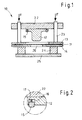
- the deep-drawing device is generally designated 10.
- This Deep-drawing device 10 is used for deep-drawing metallic, sheet-like blanks, the deep-drawing device 10 in particular for the production of Body elements is used.
- the deep-drawing device 10 includes essential, see e.g. B. Fig. 1 of the drawing, a stamp 12, a Hold-down 13 and a deep-drawing mold 14, and it further comprises at least one acting on the metallic, sheet-like board 11, preferably individually adjustable, pull rod 15.
- the at least one on the metallic, sheet-like plate 11 acting, preferably individually adjustable Drawing rod 15 is arranged directly on the punch 12 of the deep-drawing device 10.
- This arrangement ensures that the one arranged directly on the stamp 12 respective drawing rod 15 at a predetermined time during the Deep drawing process attacks on the board 11.
- the advantage of the invention lies in particular in the combination of a low inhibitory effect Material flow controlling device at the beginning of the deep-drawing process Achieving good formability with a significantly increased material flow controlling device at the end of the deep-drawing process to reduce or Avoidance of the thermoformed plate 11 jumping back.
- the deep-drawing device 10 shown in FIG. 1 of the drawing this is done a flat or preformed board 11 placed on the deep-drawing mold 14 and the Hold-down device 13 is closed.
- the Hold-down 13 controlled by quill 23 on which the hold-down 13 is fixed is.
- the deep-drawing mold 14 is arranged on a spacer 24, which in turn is on a press table 25, which is only schematically indicated here.
- the Stamp 12 is located on a plunger designated 22, which e.g. one passes here schematically indicated double-acting press device. It is also an application of the arrangement according to the invention in other than that shown press arrangements, for. B. single-acting presses etc., intended.
- FIG. 1 exactly two individually adjustable drawing rods 15 directly arranged on the punch 12 of the deep-drawing device 10.
- the amount of drawing rod 15 acting on the metallic, sheet-like plate 11 is present adjustable in order to be able to change the position of the attack on the circuit board 11.
- the shape of the drawing rod 15 can have any suitable geometry.
- the deep-drawing mold is 14 formed essentially flat.
- the deep-drawing mold 14 at the location of the respective drawing rod 15 in each case has an additional cavity 18.
- the respective drawing rod 15 on its 18 to the cavity Thermoformed mold 14 facing a convex and the cavity 18 itself one have a corresponding concave configuration.
- the respective drawing rod 15 on it to the cavity 18 of the deep-drawing mold 14 facing a substantially rectangular and the cavity 18 itself also a corresponding type have a rectangular configuration.
- the drawing rod 15 is fixed in each case the stamp 12 of the deep-drawing device 10 located pocket 16.
- the drawn rod 15 into the pocket 16 inserted intermediate plates are formed, this embodiment is in the Figures of the drawing are not shown.
- an embodiment with or possible without pockets, where the drawing rods can be exchanged without Stamps are arranged or are integrated in the stamp.
- the drawing is in the additional Cavity 18 of the deep-drawing mold 14 for more precise adjustment of the control of the Material flow a movable insert 20 is provided on the one Force resistance element 21 acts. That on this movable insert 20 acting force resistance element 21 is adjustable and is in the present case formed by spring elements, in particular by gas spring elements.
- this movable insert 20 acting force resistance element 21 is adjustable and is in the present case formed by spring elements, in particular by gas spring elements.
- other solutions can also be provided here.
- an active for additional control of the movable insert 20 hydraulic power control can be provided.
- the method according to the invention is now described below. This is characterized in that at the beginning of the deep-drawing process to increase the Formability of the circuit board 11 is a low inhibitory, controlling the material flow Device is applied to the board 11 at a predetermined rate
- the time of the deep-drawing process that inhibits the material flow Device by gripping the drawing rods 15 on the board 11 is significantly increased and that in the final part of the deep-drawing process the material flow controlling device for minimizing a jumping back of the board 11 increased is maintained.
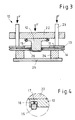
- the drawing rods 15 do not touch the circuit board 11, see 1 and 3, at this time or in this phase, the circuit board 11 but already via the punch 12 into the recess 26 of the deep-drawing mold 14 drawn.
- the material flow is controlled via the force on Hold-down device 13, via spacers between hold-down device and deep-drawing mold or optionally via additional drawing rods (not shown here) in the area of the hold-down device 13th
- the deep-drawing mold 14 is flat educated.
- the Thermoforming mold 14 has an additional cavity 18, different here Geometries with respect to the drawing rods 15 and selected according to the cavity 18 can be.
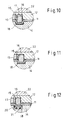
- the material flow is through this training at the final Part of the deep-drawing process additionally inhibited. If here the drawing rods 15 attack the circuit board 11, the material in this cavity 18 of the deep-drawing mold 14 pulled, see Fig. 10.
- the material flow is inhibited when the distance SDB Drawing rod 15 - cavity 18 is smaller than the original thickness S0 of the board 11, or reduced if the distance SDB drawing rod 15 - cavity 18 is equal to or is greater than the original thickness S0 of the circuit board 11. This also applies to the Embodiment according to FIG. 11.
Landscapes
- Engineering & Computer Science (AREA)
- Mechanical Engineering (AREA)
- Shaping Metal By Deep-Drawing, Or The Like (AREA)
Abstract
Description
- Fig. 1
- eine schematische Teil- Schnittansicht einer ersten Ausführungsform der erfindungsgemäßen Tiefziehvorrichtung mit geschlossenem Niederhalter in der Anfangsposition,
- Fig. 2
- eine schematische Teil- Schnittansicht eines Bereiches mit einem im Stempel integrierten Ziehstab der ersten Ausführungsform der erfindungsgemäßen Tiefziehvorrichtung gemäß Fig. 1;
- Fig. 3
- eine schematische Teil- Schnittansicht der ersten Ausführungsform der erfindungsgemäßen Tiefziehvorrichtung in der ersten Phase des Tiefziehvorganges;
- Fig. 4
- eine schematische Teil- Schnittansicht eines Bereiches mit einem im Stempel integrierten Ziehstab der ersten Ausführungsform der erfindungsgemäßen Tiefziehvorrichtung gemäß Fig. 3;
- Fig. 5
- eine schematische Teil- Schnittansicht der ersten Ausführungsform der erfindungsgemäßen Tiefziehvorrichtung in dem Moment des ersten Angreifens der Ziehstäbe an der Platine,
- Fig.6
- eine schematische Teil- Schnittansicht eines Bereiches mit einem Ziehstab der ersten Ausführungsform der Tiefziehvorrichtung in dem Moment des ersten Angreifens der Ziehstäbe an der Platine;
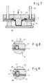
- Fig. 7
- eine schematische Teil- Schnittansicht der ersten Ausführungsform der erfindungsgemäßen Tiefziehvorrichtung in der Endphase des Tiefziehvorganges mit gehemmtem oder gestopptem Materialfluß;
- Fig.8
- eine schematische Teil- Schnittansicht eines Bereiches mit einem Ziehstab der ersten Ausführungsform der erfindungsgemäßen Tiefziehvorrichtung in der Endphase des Tiefziehvorganges;
- Fig.9
- eine schematische Teil- Schnittansicht eines Bereiches mit einem Ziehstab einer abgewandelten Ausführungsform der erfindungsgemäßen Tiefziehvorrichtung mit gehemmtem oder gestopptem Materialfluß in der Endphase des Tiefziehprozesses;
- Fig. 10
- eine schematische Teil- Schnittansicht eines Bereiches mit einem Ziehstab einer anderen abgewandelten Ausführungsform der erfindungsgemäßen Tiefziehvorrichtung in der Endphase des Tiefziehprozesses;
- Fig. 11
- eine schematische Teil- Schnittansicht eines Bereiches mit einem Ziehstab einer weiteren abgewandelten Ausführungsform der erfindungsgemäßen Tiefziehvorrichtung in der Endphase des Tiefziehprozesses; und
- Fig. 12
- eine schematische Teil- Schnittansicht eines Bereiches mit einem Ziehstab einer letzten abgewandelten Ausführungsform der erfindungsgemäßen Tiefziehvorrichtung in der Endphase des Tiefziehprozesses.
Claims (25)
- Tiefziehvorrichtung (10) zum Tiefziehen von metallischen, blechartigen Platinen (11), umfassend im wesentlichen einen Stempel (12), einen Niederhalter (13) und eine Tiefziehform (14), und umfassend wenigstens einen auf die metallische, blechartige Platine (11) einwirkenden, insbesondere einzeln verstellbaren, Ziehstab (15),
dadurch gekennzeichnet, daß
der wenigstens eine auf die metallische, blechartige Platine (11) einwirkende, insbesondere einzeln steuerbare Ziehstab (15) direkt am Stempel (12) der Tiefziehvorrichtung (10) angeordnet ist. - Tiefziehvorrichtung nach Anspruch 1,
dadurch gekennzeichnet, daß
ein oder mehrere verstellbare Ziehstäbe (15) direkt am Stempel (12) der Tiefziehvorrichtung (10) angeordnet sind. - Tiefziehvorrichtung nach Anspruch 1 oder 2,
dadurch gekennzeichnet, daß
der wenigstens eine auf die metallische, blechartige Platine (11) einwirkende, insbesondere einzeln verstellbare, direkt am Stempel (12) der Tiefziehvorrichtung (10) angeordnete Ziehstab (15) austauschbar ausgebildet ist. - Tiefziehvorrichtung nach einem der Ansprüche 1 bis 3,
dadurch gekennzeichnet, daß
der wenigstens eine auf die metallische, blechartige Platine (11) einwirkende Ziehstab (15) jeweils in einer im Stempel (12) der Tiefziehvorrichtung (10) befindlichen Tasche (16) angeordnet ist. - Tiefziehvorrichtung nach einem der Ansprüche 1 bis 4,
dadurch gekennzeichnet, daß
die Höhe des wenigstens einen auf die metallische, blechartige Platine (11) einwirkenden Ziehstabes (15) einstellbar ist. - Tiefziehvorrichtung nach einem der Ansprüche 1 bis 5,
dadurch gekennzeichnet, daß
zur funktionsgerechten Einwirkung des wenigstens einen Ziehstabes (15) auf die metallische, blechartige Platine (11) ein zusätzliches, auf den Ziehstab (15) einwirkendes, Kraftwiderstandselement (17) vorgesehen ist. - Tiefziehvorrichtung nach Anspruch 6,
dadurch gekennzeichnet, daß
das auf den Ziehstab (15) einwirkende, zusätzliche Kraftwiderstandselement (17) einstellbar ausgebildet ist. - Tiefziehvorrichtung nach Anspruch 7,
dadurch gekennzeichnet, daß
das auf den Ziehstab (15) einwirkende, zusätzliche Kraftwiderstandselement (17) durch ein Federelement, insbesondere ein Gas- Federelement, gebildet ist. - Tiefziehvorrichtung nach einem der Ansprüche 6 bis 8,
dadurch gekennzeichnet, daß
zur zusätzlichen Verstellung des jeweiligen Ziehstabes (15) der Tiefziehvorrichtung (10) eine aktive hydraulische Kraftsteuerung vorgesehen ist. - Tiefziehvorrichtung nach einem der Ansprüche 1 bis 9,
dadurch gekennzeichnet, daß
die Tiefziehform (14) im wesentlichen eben ausgebildet ist. - Tiefziehvorrichtung nach einem der Ansprüche 1 bis 9,
dadurch gekennzeichnet, daß
die Tiefziehform (14) an der Stelle des jeweils einwirkenden Ziehstabes (15) jeweils eine zusätzliche Aushöhlung (18) aufweist. - Tiefziehvorrichtung nach Anspruch 11,
dadurch gekennzeichnet, daß
der wenigstens eine Ziehstab (15) an seiner zur Aushöhlung (18) der Tiefziehform (14) gerichteten Seite eine konvexe und die Aushöhlung (18) selbst eine entsprechend geartete konkave Ausgestaltung aufweist. - Tiefziehvorrichtung nach Anspruch 12,
dadurch gekennzeichnet, daß
der wenigstens eine Ziehstab (15) an seiner zur Aushöhlung (18) der Tiefziehform (14) gerichteten Seite eine im wesentlichen rechteckige und die Aushöhlung (18) selbst ebenfalls eine entsprechend geartete rechteckige Ausgestaltung aufweist. - Tiefziehvorrichtung nach Anspruch 12 oder 13,
dadurch gekennzeichnet, daß
die Tiefziehform konkave, konvexe und/oder im wesentlichen rechteckige Aufhöhlungen (18) besitzt und der mindestens eine Ziehstab (15) eine entsprechend geartete Ausgestaltet aufweist. - Tiefziehvorrichtung nach einem der Ansprüche 1 bis 14,
dadurch gekennzeichnet, daß
der wenigstens eine Ziehstab (15) jeweils fest in der an dem Stempel (12) der Tiefziehvorrichtung (10) befindlichen Tasche (16) festgelegt ist. - Tiefziehvorrichtung nach Anspruch 15,
dadurch gekennzeichnet, daß
der zur Einstellung der Höhe des fest in der an dem Stempel (12) befindlichen Tasche (16) festgelegten Ziehstabes (15) in die Tasche (16) eingesetzte Zwischenplatten ausgebildet sind. - Tiefziehvorrichtung nach einem der Ansprüche 11 bis 16,
dadurch gekennzeichnet, daß
in der zusätzlichen Aushöhlung (18) der Tiefziehform (14) zur genaueren Einstellung der Steuerung des Materialflusses ein beweglicher Einsatz (20) vorgesehen ist, auf den ein Kraftwiderstandselement (21) einwirkt. - Tiefziehvorrichtung nach Anspruch 17,
dadurch gekennzeichnet, daß
das auf den beweglichen Einsatz (20) in der Aushöhlung (18) der Tiefziehform (14) einwirkende Kraftwiderstandselement (21) einstellbar ausgebildet ist. - Tiefziehvorrichtung nach Anspruch 18,
dadurch gekennzeichnet, daß
das auf den beweglichen Einsatz (20) einwirkende Kraftwiderstandselement (21) durch Federelemente, insbesondere durch Gas- Federelemente, gebildet ist. - Tiefziehvorrichtung nach einem der Ansprüche 17 bis 19,
dadurch gekennzeichnet, daß
zur zusätzlichen Einstellung des beweglichen Einsatzes (20) eine aktive hydraulische Kraftsteuerung vorgesehen ist. - Verfahren zum Tiefziehen von metallischen, blechartigen Platinen (11), bei dem das zu bearbeitende Platine (11) in einer Tiefziehvorrichtung (10) über einen Niederhalter (13) und eine entsprechende Gegenanschlagfläche der Tiefziehform (14) eingeklemmt und über auf dieses Platine (11) einwirkende Ziehstäbe (15) der Materialfluß im wesentlichen gesteuert wird,
dadurch gekennzeichnet, daß
zu Beginn des Tiefziehvorganges zur Erhöhung der Umformbarkeit der Platine (11) eine geringe hemmende, den Materialfluß steuernde Einrichtung auf die Platine (11) aufgebracht wird, daß zu einem vorbestimmten Zeitpunkt des Tiefziehvorganges die hemmende, den Materialfluß steuernde Einrichtung durch Angreifen der Ziehstäbe (15) auf die Platine (11) deutlich erhöht wird und daß beim abschließenden Teil des Tiefziehvorganges die den Materialfluß steuernde Einrichtung zur Minimierung eines Zurückspringens der Platine (11) erhöht beibehalten wird. - Verfahren nach Anspruch 21,
dadurch gekennzeichnet, daß
zu Beginn des Tiefziehvorganges die Ziehstäbe (15) nicht an der Platine (11) angreifen. - Verfahren nach Anspruch 21 oder 22,
dadurch gekennzeichnet, daß
nach 80 bis 97 % des gesamten Tiefziehvorganges die hemmende, den Materialfluß steuernde Kraft durch Angreifen der Ziehstäbe (15) auf die Platine (11) deutlich erhöht wird. - Verfahren nach einem der Ansprüche 21 bis 23,
dadurch gekennzeichnet, daß
beim abschließenden Teil des Tiefziehvorganges die den Materialfluß steuernde Kraft bei einer vorbestimmten Position an der Platine (11) angreift, derart, daß der Materialfluß bis zum Ende des Tiefziehvorganges wesentlich reduziert oder gehemmt wird. - Verfahren nach einem der Ansprüche 21 bis 24,
dadurch gekennzeichnet, daß
der Materialfluß beim abschließenden Teil des Tiefziehvorganges neben dem Aufbringen der den Tiefziehvorgang steuernden Kraft zusätzlich gehemmt wird.
Priority Applications (2)
| Application Number | Priority Date | Filing Date | Title |
|---|---|---|---|
| DE50203897T DE50203897D1 (de) | 2002-09-07 | 2002-09-07 | Tiefziehvorrichtung und Verfahren zum Tiefziehen |
| EP20020020094 EP1396297B1 (de) | 2002-09-07 | 2002-09-07 | Tiefziehvorrichtung und Verfahren zum Tiefziehen |
Applications Claiming Priority (1)
| Application Number | Priority Date | Filing Date | Title |
|---|---|---|---|
| EP20020020094 EP1396297B1 (de) | 2002-09-07 | 2002-09-07 | Tiefziehvorrichtung und Verfahren zum Tiefziehen |
Publications (2)
| Publication Number | Publication Date |
|---|---|
| EP1396297A1 true EP1396297A1 (de) | 2004-03-10 |
| EP1396297B1 EP1396297B1 (de) | 2005-08-10 |
Family
ID=31502747
Family Applications (1)
| Application Number | Title | Priority Date | Filing Date |
|---|---|---|---|
| EP20020020094 Expired - Lifetime EP1396297B1 (de) | 2002-09-07 | 2002-09-07 | Tiefziehvorrichtung und Verfahren zum Tiefziehen |
Country Status (2)
| Country | Link |
|---|---|
| EP (1) | EP1396297B1 (de) |
| DE (1) | DE50203897D1 (de) |
Cited By (2)
| Publication number | Priority date | Publication date | Assignee | Title |
|---|---|---|---|---|
| DE102006003268A1 (de) * | 2006-01-24 | 2007-08-09 | Ford Global Technologies, LLC, Dearborn | Verfahren sowie Tiefziehvorrichtung zum Tiefziehen von Metallblechen |
| CN112654564A (zh) * | 2018-11-02 | 2021-04-13 | 必达包装国际有限公司 | 金属箔容器 |
Families Citing this family (1)
| Publication number | Priority date | Publication date | Assignee | Title |
|---|---|---|---|---|
| CN104043713A (zh) * | 2014-06-26 | 2014-09-17 | 梧州恒声电子科技有限公司 | 一种双动压力机拉伸模具工艺 |
Citations (4)
| Publication number | Priority date | Publication date | Assignee | Title |
|---|---|---|---|---|
| DE2828431A1 (de) * | 1978-06-08 | 1979-12-13 | Aluminiumwerke Ag Rorschach | Vorrichtung zum tiefziehen eines ziehteiles |
| JPS58157531A (ja) * | 1982-03-16 | 1983-09-19 | Nissan Motor Co Ltd | プレス型 |
| DE19504649C1 (de) * | 1995-02-13 | 1996-08-22 | Daimler Benz Ag | Verfahren und Ziehwerkzeug zum Streckziehen von Blechen |
| US6276185B1 (en) * | 1999-12-09 | 2001-08-21 | General Motors Corporation | Flow lock bead control apparatus and method for drawing high strength steel |
-
2002
- 2002-09-07 EP EP20020020094 patent/EP1396297B1/de not_active Expired - Lifetime
- 2002-09-07 DE DE50203897T patent/DE50203897D1/de not_active Expired - Lifetime
Patent Citations (4)
| Publication number | Priority date | Publication date | Assignee | Title |
|---|---|---|---|---|
| DE2828431A1 (de) * | 1978-06-08 | 1979-12-13 | Aluminiumwerke Ag Rorschach | Vorrichtung zum tiefziehen eines ziehteiles |
| JPS58157531A (ja) * | 1982-03-16 | 1983-09-19 | Nissan Motor Co Ltd | プレス型 |
| DE19504649C1 (de) * | 1995-02-13 | 1996-08-22 | Daimler Benz Ag | Verfahren und Ziehwerkzeug zum Streckziehen von Blechen |
| US6276185B1 (en) * | 1999-12-09 | 2001-08-21 | General Motors Corporation | Flow lock bead control apparatus and method for drawing high strength steel |
Non-Patent Citations (1)
| Title |
|---|
| PATENT ABSTRACTS OF JAPAN vol. 007, no. 283 (M - 263) 16 December 1983 (1983-12-16) * |
Cited By (4)
| Publication number | Priority date | Publication date | Assignee | Title |
|---|---|---|---|---|
| DE102006003268A1 (de) * | 2006-01-24 | 2007-08-09 | Ford Global Technologies, LLC, Dearborn | Verfahren sowie Tiefziehvorrichtung zum Tiefziehen von Metallblechen |
| DE102006003268B4 (de) * | 2006-01-24 | 2008-02-07 | Ford Global Technologies, LLC, Dearborn | Verfahren sowie Tiefziehvorrichtung zum Tiefziehen von Metallblechen |
| CN112654564A (zh) * | 2018-11-02 | 2021-04-13 | 必达包装国际有限公司 | 金属箔容器 |
| CN112654564B (zh) * | 2018-11-02 | 2023-02-28 | 必达包装国际有限公司 | 金属箔容器 |
Also Published As
| Publication number | Publication date |
|---|---|
| EP1396297B1 (de) | 2005-08-10 |
| DE50203897D1 (de) | 2005-09-15 |
Similar Documents
| Publication | Publication Date | Title |
|---|---|---|
| EP2103423B1 (de) | Pulverpresse zur Herstellung eines Presslings aus Metallpulver | |
| EP1986801B1 (de) | Verfahren und vorrichtung zum herstellen eines ausschnittes oder durchbruchs in der wandung eines nach dem innenhochdruck-umformverfahren ausgebildeten bauteils | |
| EP2802425B1 (de) | Vorrichtung und verfahren zum tiefziehen von schalenteilen mit integriertem kopf- und zargenbeschnitt | |
| DE102011116714A1 (de) | Werkzeug und Verfahren zum Warmformen und Schneiden, insbesondere zum Presshärten und Schneiden, eines Blechmaterials | |
| DE102009003668A1 (de) | Verfahren und Vorrichtung zur Herstellung geschlossener Profile | |
| WO2011083008A1 (de) | Verfahren und vorrichtung zur herstellung eines halbschalenteils | |
| DE102009057726A1 (de) | Radialpresse | |
| EP2036631A1 (de) | Verfahren und Vorrichtung zum Herstellen von Stanzteilen mit vergrösserter Funktionsfläche | |
| EP0873855A2 (de) | Verfahren und Vorrichtung zur Herstellung von Presslingen aus Hartmetall, Keramik, Sintermetall oder dergleichen | |
| EP0704258A1 (de) | Verfahren und Vorrichtung zum Umformen von Metallblech | |
| WO2014012831A1 (de) | Verfahren zum herstellen eines umgeformten und zumindest bereichsweise gehärteten metallblechbauteils sowie presshärtwerkzeug zum herstellen eines solchen bauteiles | |
| DE19647963A1 (de) | Verfahren und Vorrichtung zur Herstellung von Löchern am Umfang von Hohlprofilen | |
| DE102013019634A1 (de) | Herstellung eines Blechformteils mit lokalem elektromagnetischen Umformen des Blechmaterials zur Erzeugung einer Blechformteilkante | |
| DE102006026805A1 (de) | Vorrichtung und Verfahren zum Warmumformen eines Halbzeugs | |
| EP1396297B1 (de) | Tiefziehvorrichtung und Verfahren zum Tiefziehen | |
| EP1447153A1 (de) | Werkzeugmaschine für das Aussenhochdruckumformen von Platinen | |
| EP2839900B1 (de) | Verfahren und Vorrichtung zur Herstellung eines mit einer Endfläche versehenen Verbindungsabschnitts als Teil eines Werkzeuges | |
| DE102014110400B4 (de) | Etagenpressumformwerkzeug | |
| EP0682999A2 (de) | Pressteil aus Metallpulver, Verfahren und Vorrichtung zu seiner Herstellung | |
| DE102008004898A1 (de) | Pressteilanheber | |
| DE10214008A1 (de) | Verfahren und Vorrichtung zum Hinterspritzen | |
| DE3136753C2 (de) | Tiefzieheinrichtung für Platine | |
| DE102007044259B4 (de) | Ziehwerkzeug mit kurzem Kraftweg | |
| DE10120880B4 (de) | Verfahren zur Herstellung von Tiefziehteilen | |
| EP1047513B1 (de) | Verfahren zum bearbeiten eines werkstückes und zugehörige vorrichtung |
Legal Events
| Date | Code | Title | Description |
|---|---|---|---|
| PUAI | Public reference made under article 153(3) epc to a published international application that has entered the european phase |
Free format text: ORIGINAL CODE: 0009012 |
|
| AK | Designated contracting states |
Kind code of ref document: A1 Designated state(s): AT BE BG CH CY CZ DE DK EE ES FI FR GB GR IE IT LI LU MC NL PT SE SK TR |
|
| AX | Request for extension of the european patent |
Extension state: AL LT LV MK RO SI |
|
| 17P | Request for examination filed |
Effective date: 20030110 |
|
| 17Q | First examination report despatched |
Effective date: 20040812 |
|
| AKX | Designation fees paid |
Designated state(s): DE FR GB |
|
| GRAP | Despatch of communication of intention to grant a patent |
Free format text: ORIGINAL CODE: EPIDOSNIGR1 |
|
| RAP1 | Party data changed (applicant data changed or rights of an application transferred) |
Owner name: FORD GLOBAL TECHNOLOGIES, LLC |
|
| GRAS | Grant fee paid |
Free format text: ORIGINAL CODE: EPIDOSNIGR3 |
|
| GRAA | (expected) grant |
Free format text: ORIGINAL CODE: 0009210 |
|
| AK | Designated contracting states |
Kind code of ref document: B1 Designated state(s): DE FR GB |
|
| REG | Reference to a national code |
Ref country code: GB Ref legal event code: FG4D Free format text: NOT ENGLISH |
|
| REF | Corresponds to: |
Ref document number: 50203897 Country of ref document: DE Date of ref document: 20050915 Kind code of ref document: P |
|
| GBT | Gb: translation of ep patent filed (gb section 77(6)(a)/1977) | ||
| ET | Fr: translation filed | ||
| RAP2 | Party data changed (patent owner data changed or rights of a patent transferred) |
Owner name: FORD GLOBAL TECHNOLOGIES, LLC. |
|
| PLBE | No opposition filed within time limit |
Free format text: ORIGINAL CODE: 0009261 |
|
| STAA | Information on the status of an ep patent application or granted ep patent |
Free format text: STATUS: NO OPPOSITION FILED WITHIN TIME LIMIT |
|
| 26N | No opposition filed |
Effective date: 20060511 |
|
| PGFP | Annual fee paid to national office [announced via postgrant information from national office to epo] |
Ref country code: FR Payment date: 20140825 Year of fee payment: 13 Ref country code: GB Payment date: 20140826 Year of fee payment: 13 |
|
| PGFP | Annual fee paid to national office [announced via postgrant information from national office to epo] |
Ref country code: DE Payment date: 20140930 Year of fee payment: 13 |
|
| REG | Reference to a national code |
Ref country code: DE Ref legal event code: R119 Ref document number: 50203897 Country of ref document: DE |
|
| GBPC | Gb: european patent ceased through non-payment of renewal fee |
Effective date: 20150907 |
|
| REG | Reference to a national code |
Ref country code: FR Ref legal event code: ST Effective date: 20160531 |
|
| PG25 | Lapsed in a contracting state [announced via postgrant information from national office to epo] |
Ref country code: DE Free format text: LAPSE BECAUSE OF NON-PAYMENT OF DUE FEES Effective date: 20160401 Ref country code: GB Free format text: LAPSE BECAUSE OF NON-PAYMENT OF DUE FEES Effective date: 20150907 |
|
| PG25 | Lapsed in a contracting state [announced via postgrant information from national office to epo] |
Ref country code: FR Free format text: LAPSE BECAUSE OF NON-PAYMENT OF DUE FEES Effective date: 20150930 |