EP1396027B1 - Einrichtungen zur bidirektionalen unterdrückung von spannungstransienten mit niedriger durchschlagspannung und verfahren zu ihrer herstellung - Google Patents
Einrichtungen zur bidirektionalen unterdrückung von spannungstransienten mit niedriger durchschlagspannung und verfahren zu ihrer herstellung Download PDFInfo
- Publication number
- EP1396027B1 EP1396027B1 EP02729288A EP02729288A EP1396027B1 EP 1396027 B1 EP1396027 B1 EP 1396027B1 EP 02729288 A EP02729288 A EP 02729288A EP 02729288 A EP02729288 A EP 02729288A EP 1396027 B1 EP1396027 B1 EP 1396027B1
- Authority
- EP
- European Patent Office
- Prior art keywords
- layer
- epitaxial
- voltage
- breakdown
- conductivity type
- Prior art date
- Legal status (The legal status is an assumption and is not a legal conclusion. Google has not performed a legal analysis and makes no representation as to the accuracy of the status listed.)
- Expired - Lifetime
Links
- 230000001629 suppression Effects 0.000 title claims description 28
- 238000000034 method Methods 0.000 title claims description 16
- 230000015556 catabolic process Effects 0.000 claims description 64
- ZOXJGFHDIHLPTG-UHFFFAOYSA-N Boron Chemical compound [B] ZOXJGFHDIHLPTG-UHFFFAOYSA-N 0.000 claims description 16
- 229910052796 boron Inorganic materials 0.000 claims description 16
- 239000002019 doping agent Substances 0.000 claims description 16
- BHEPBYXIRTUNPN-UHFFFAOYSA-N hydridophosphorus(.) (triplet) Chemical compound [PH] BHEPBYXIRTUNPN-UHFFFAOYSA-N 0.000 claims description 14
- 239000000758 substrate Substances 0.000 claims description 14
- 230000001052 transient effect Effects 0.000 claims description 12
- 238000000151 deposition Methods 0.000 claims description 10
- 239000004065 semiconductor Substances 0.000 claims description 10
- 230000008021 deposition Effects 0.000 claims description 7
- 238000010438 heat treatment Methods 0.000 claims description 3
- 238000004519 manufacturing process Methods 0.000 claims description 3
- 238000009792 diffusion process Methods 0.000 description 24
- 235000012431 wafers Nutrition 0.000 description 16
- VYPSYNLAJGMNEJ-UHFFFAOYSA-N Silicium dioxide Chemical compound O=[Si]=O VYPSYNLAJGMNEJ-UHFFFAOYSA-N 0.000 description 10
- 230000008901 benefit Effects 0.000 description 8
- 229910052814 silicon oxide Inorganic materials 0.000 description 8
- 229910052581 Si3N4 Inorganic materials 0.000 description 6
- 125000004429 atom Chemical group 0.000 description 6
- 230000003647 oxidation Effects 0.000 description 6
- 238000007254 oxidation reaction Methods 0.000 description 6
- HQVNEWCFYHHQES-UHFFFAOYSA-N silicon nitride Chemical compound N12[Si]34N5[Si]62N3[Si]51N64 HQVNEWCFYHHQES-UHFFFAOYSA-N 0.000 description 6
- XUIMIQQOPSSXEZ-UHFFFAOYSA-N Silicon Chemical compound [Si] XUIMIQQOPSSXEZ-UHFFFAOYSA-N 0.000 description 5
- 230000008569 process Effects 0.000 description 5
- 238000012545 processing Methods 0.000 description 5
- 229910052710 silicon Inorganic materials 0.000 description 5
- 239000010703 silicon Substances 0.000 description 5
- 230000015572 biosynthetic process Effects 0.000 description 4
- 238000010924 continuous production Methods 0.000 description 4
- 238000007796 conventional method Methods 0.000 description 4
- 230000009467 reduction Effects 0.000 description 4
- QTBSBXVTEAMEQO-UHFFFAOYSA-N Acetic acid Chemical compound CC(O)=O QTBSBXVTEAMEQO-UHFFFAOYSA-N 0.000 description 3
- 238000013459 approach Methods 0.000 description 3
- 238000005452 bending Methods 0.000 description 3
- 230000006378 damage Effects 0.000 description 3
- 230000007423 decrease Effects 0.000 description 3
- 239000010432 diamond Substances 0.000 description 3
- 238000005530 etching Methods 0.000 description 3
- 230000001590 oxidative effect Effects 0.000 description 3
- 229920002120 photoresistant polymer Polymers 0.000 description 3
- 230000002441 reversible effect Effects 0.000 description 3
- 238000012360 testing method Methods 0.000 description 3
- PXHVJJICTQNCMI-UHFFFAOYSA-N Nickel Chemical compound [Ni] PXHVJJICTQNCMI-UHFFFAOYSA-N 0.000 description 2
- 230000000694 effects Effects 0.000 description 2
- 230000005684 electric field Effects 0.000 description 2
- 230000000873 masking effect Effects 0.000 description 2
- 150000004767 nitrides Chemical class 0.000 description 2
- GRYLNZFGIOXLOG-UHFFFAOYSA-N Nitric acid Chemical compound O[N+]([O-])=O GRYLNZFGIOXLOG-UHFFFAOYSA-N 0.000 description 1
- OAICVXFJPJFONN-UHFFFAOYSA-N Phosphorus Chemical compound [P] OAICVXFJPJFONN-UHFFFAOYSA-N 0.000 description 1
- 238000005275 alloying Methods 0.000 description 1
- XAGFODPZIPBFFR-UHFFFAOYSA-N aluminium Chemical compound [Al] XAGFODPZIPBFFR-UHFFFAOYSA-N 0.000 description 1
- 229910052782 aluminium Inorganic materials 0.000 description 1
- 238000003486 chemical etching Methods 0.000 description 1
- 238000010276 construction Methods 0.000 description 1
- 238000013461 design Methods 0.000 description 1
- 230000003292 diminished effect Effects 0.000 description 1
- 230000003467 diminishing effect Effects 0.000 description 1
- 238000009826 distribution Methods 0.000 description 1
- 239000000428 dust Substances 0.000 description 1
- 230000035784 germination Effects 0.000 description 1
- 238000002955 isolation Methods 0.000 description 1
- 238000004518 low pressure chemical vapour deposition Methods 0.000 description 1
- 239000000463 material Substances 0.000 description 1
- 229910052759 nickel Inorganic materials 0.000 description 1
- 229910017604 nitric acid Inorganic materials 0.000 description 1
- 238000002161 passivation Methods 0.000 description 1
- 125000004437 phosphorous atom Chemical group 0.000 description 1
- 229910052698 phosphorus Inorganic materials 0.000 description 1
- 239000011574 phosphorus Substances 0.000 description 1
- 238000001020 plasma etching Methods 0.000 description 1
- 238000007747 plating Methods 0.000 description 1
- 239000002994 raw material Substances 0.000 description 1
- 230000004044 response Effects 0.000 description 1
- 238000012552 review Methods 0.000 description 1
- 235000012239 silicon dioxide Nutrition 0.000 description 1
- 239000000377 silicon dioxide Substances 0.000 description 1
- 238000007669 thermal treatment Methods 0.000 description 1
- 230000009466 transformation Effects 0.000 description 1
- 230000005641 tunneling Effects 0.000 description 1
- 238000009279 wet oxidation reaction Methods 0.000 description 1
Images


Classifications
-
- H—ELECTRICITY
- H01—ELECTRIC ELEMENTS
- H01L—SEMICONDUCTOR DEVICES NOT COVERED BY CLASS H10
- H01L29/00—Semiconductor devices specially adapted for rectifying, amplifying, oscillating or switching and having potential barriers; Capacitors or resistors having potential barriers, e.g. a PN-junction depletion layer or carrier concentration layer; Details of semiconductor bodies or of electrodes thereof ; Multistep manufacturing processes therefor
- H01L29/66—Types of semiconductor device ; Multistep manufacturing processes therefor
- H01L29/86—Types of semiconductor device ; Multistep manufacturing processes therefor controllable only by variation of the electric current supplied, or only the electric potential applied, to one or more of the electrodes carrying the current to be rectified, amplified, oscillated or switched
- H01L29/861—Diodes
-
- H—ELECTRICITY
- H01—ELECTRIC ELEMENTS
- H01L—SEMICONDUCTOR DEVICES NOT COVERED BY CLASS H10
- H01L29/00—Semiconductor devices specially adapted for rectifying, amplifying, oscillating or switching and having potential barriers; Capacitors or resistors having potential barriers, e.g. a PN-junction depletion layer or carrier concentration layer; Details of semiconductor bodies or of electrodes thereof ; Multistep manufacturing processes therefor
- H01L29/66—Types of semiconductor device ; Multistep manufacturing processes therefor
- H01L29/66007—Multistep manufacturing processes
- H01L29/66075—Multistep manufacturing processes of devices having semiconductor bodies comprising group 14 or group 13/15 materials
- H01L29/66083—Multistep manufacturing processes of devices having semiconductor bodies comprising group 14 or group 13/15 materials the devices being controllable only by variation of the electric current supplied or the electric potential applied, to one or more of the electrodes carrying the current to be rectified, amplified, oscillated or switched, e.g. two-terminal devices
- H01L29/6609—Diodes
- H01L29/66121—Multilayer diodes, e.g. PNPN diodes
-
- H—ELECTRICITY
- H01—ELECTRIC ELEMENTS
- H01L—SEMICONDUCTOR DEVICES NOT COVERED BY CLASS H10
- H01L29/00—Semiconductor devices specially adapted for rectifying, amplifying, oscillating or switching and having potential barriers; Capacitors or resistors having potential barriers, e.g. a PN-junction depletion layer or carrier concentration layer; Details of semiconductor bodies or of electrodes thereof ; Multistep manufacturing processes therefor
- H01L29/66—Types of semiconductor device ; Multistep manufacturing processes therefor
- H01L29/86—Types of semiconductor device ; Multistep manufacturing processes therefor controllable only by variation of the electric current supplied, or only the electric potential applied, to one or more of the electrodes carrying the current to be rectified, amplified, oscillated or switched
- H01L29/861—Diodes
- H01L29/8618—Diodes with bulk potential barrier, e.g. Camel diodes, Planar Doped Barrier diodes, Graded bandgap diodes
Definitions
- the present invention relates to semiconductor devices. More particularly, the present invention relates to low-voltage punch-through bi-directional transient-voltage suppression devices having symmetric current-voltage characteristics.
- n+p-p+n+ devices of U.S. Patent No. 5,880,511 are also claimed to be superior to other transient-voltage suppression devices, specifically n+pn+ uniform-base punch-through devices, which are claimed to suffer from poor clamping characteristics at high currents.
- n+p-p+n+ devices such as those described in U.S. Patent No.
- a bi-directional transient voltage suppression device with symmetric current-voltage characteristics according to claim 1 is provided.
- Phosphorous is preferably used as an n-type dopant, and boron is used as a p-type dopant.
- the peak net doping concentration of each of the first and second epitaxial p+ layers ranges from 5 to 20 times the peak net doping concentration of the epitaxial n layer.
- the peak net doping concentration of the epitaxial n layer ranges from 2 x 10 16 cm -3 to 2 x 10 17 cm -3
- the peak net doping concentration of the first and second epitaxial p+ layers range from 2 x 10 17 cm -3 to 2 x 10 18 cm -3 .
- the preferred distance between the upper and lower junctions ranges from 0.2 to 1.5 ⁇ m [microns].
- the first and second epitaxial p+ layers are preferably sufficiently thick to more evenly distribute electrical current throughout the device. It is also preferred that the minority lifetime, punch through breakdown voltage, and theoretical avalanche breakdown voltage be selected so as to produce a Vceo having negative dynamic resistance that compensates for at least a portion of the positive dynamic resistance of the device in the on state.
- a method of claim 7 of making a bi-directional transient voltage suppression device is provided.
- the n epitaxial layer is grown to a thickness ranging from 1 to 4 ⁇ m [microns], with the distance between junctions ranging from 0.2 to 1.5 ⁇ m [microns] after heating.
- the doping concentration of the upper p+ epitaxial layer upon deposition is preferably between 1% and 8% less than the doping of the lower p+ epitaxial layer upon deposition.
- One advantage of the present invention is that a low-voltage bi-directional transient-voltage suppressor is provided that has a low leakage current.
- a further advantage of the present invention is that a low-voltage bi-directional transient-voltage suppressor is provided that has a lower capacitance than the Zener transient-voltage suppression device with the same breakdown voltage.
- Yet another advantage of the present invention is that a low-voltage bi-directional transient-voltage suppressor is provided which has symmetric current-voltage characteristics. This is in contrast to, for example, the n+p-p+n+ devices described in U.S. Patent No. 5,880,511 .
- Yet another advantage of the present invention is that a low-voltage bi-directional transient-voltage suppressor is provided which has acceptable clamping characteristics at high currents. More specifically, as noted above, U.S. Patent No. 5,880,511 claims that n+pn+ uniform-base punch-through devices suffer from poor clamping characteristics at high currents. A base with a uniform carrier concentration is indeed in danger of becoming intrinsic at temperatures that are lower than most other constructions. High temperature protection is important, for example, during power surges in which the region bordering the junction can rise by several hundred °C within milliseconds.
- a base with a high-doped portion and a low-doped portion will perform better than a uniformly doped base of intermediate doping concentration, because the high-doped portion will become intrinsic at a higher temperature.
- One approach is to put a high-doped portion on one side of the base, as proposed in U.S. Patent No. 5,880,511 .
- the devices of the present invention take another approach by placing the high-doped portion in the center of the base. In this way, the device of the present invention does not give up current-voltage symmetry, while being able to provide a base with a peak doping concentration that is higher (and hence an intrinsic temperature that is higher) than that found in a uniform-base device.
- a base with these characteristics is achieved with a single epitaxial layer in preferred embodiments of the invention, other options are available.
- a base layer containing three epitaxial sub-layers, each with a homogeneous concentration is contemplated.
- the center base sublayer of such a device could occupy approximately 10% of the width of the total base and have ten times the concentration of the outer base sub-layers, which would divide the rest of the base width equally.
- Another advantage of the present invention is that low-voltage bi-directional transient-voltage suppressors are provided that offer protection against surface breakdown. In the punch-through devices of the present invention, this means ensuring that the depletion layer does not reach the opposing junction at the surface before reaching it in the bulk.
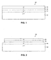
- Figure 1 is a cross-sectional view (not to scale) of a triple epitaxial structure for a low-voltage bi-directional transient-voltage suppressor device according to an embodiment of the present invention.
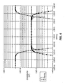
- Figure 2 is a cross-sectional view (not to scale) of the triple epitaxial structure according to Figure 1 after formation of a mesa structure.
- Figure 3 is a plot of acceptor (boron) concentration (indicated by diamonds) and net donor concentration (indicated by squares) as a function of thickness for a structure in accordance with the present invention after growth of the epitaxial layers.
- Figure 4 is an expanded view (with the horizontal scale more than 10 times enlarged) of a portion of Figure 3 .
- acceptor (boron) concentration is indicated by diamonds
- donor (phosphorous) concentration is indicated by squares
- net donor (donor-acceptor) concentration is indicated by triangles.
- Figure 5 illustrates acceptor (boron) concentration (indicated by diamonds), donor (phosphorous) concentration (indicated by squares), and net donor concentration (indicated by triangles) as a function of thickness for the device of Figure 4 after a certain amount of diffusion of both the boron and the phosphorous atoms.
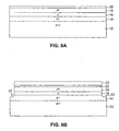
- Figure 6 is a cross-sectional view (not to scale) of a triple epitaxial structure, but with a silicon oxide sidewall provided, according to an embodiment of the present invention.
- Figure 7 is an expanded view (not to scale) of region A of Figure 6 , illustrating how the junctions curve away from one another.
- Figures 8A-8C are cross-sectional views (not to scale) illustrating a process for making a triple epitaxial device with a silicon oxide sidewall according to an embodiment of the present invention.
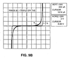
- Figures 9A and 9B are current-voltage traces illustrating the bi-directional breakdown characteristics for a bi-directional transient-voltage suppression device of the present invention (curve b) and a commercially available bi-directional transient-voltage suppressor (curve a).
- the current scale is 2mA/step.
- the vertical (current) scale is expanded to 200 ⁇ A/step.
- a p++p+np+ triple-epitaxial punch-through bi-directional transient-voltage suppressor 10 is shown schematically in cross sectional view.
- the device of the present invention is formed on a p++ semiconductor substrate 12.
- three regions are epitaxially grown, preferably in one continuous process.
- a first epitaxial p+ region 14 is initially formed on the upper surface of p++ region 12.
- An epitaxial n region 16 is then formed on the upper surface ofp+ region 14, and a second epitaxial p+ region 18 is formed on the upper surface of n region 16.
- a p++ ohmic contact (not shown) is typically provided on the upper surface of p+ region 18.
- Such a device contains two junctions: (1) the junction formed at the interface of epitaxially grown p+ region 14 and epitaxially grown n region 16, and (2) the junction formed at the interface of epitaxially grown n region 16 and epitaxially grown p+ region 18.
- the bi-directional transient-voltage suppressor 10 of FIG. 1 is typically provided with a mesa structure for junction germination.
- a structure like that shown in Figs. 1 and 2 is advantageous for several reasons.
- the epitaxial layers can be grown in one continuous process, from the same raw materials, the p+ resistivity on both sides of the n layer can be matched to a much higher precision than would be the case if the first p+ layer would be replaced by a p+ substrate with, officially, the same resistivity.
- a much more symmetric breakdown voltage can be so established for both junctions with a triple epitaxial scheme.
- experimental results have confirmed that the breakdown voltage is very symmetric for such a device, with less than a 2% difference being measured between forward and reverse breakdown voltage at 1.0 mA.
- n++n+pn+ triple-epitaxial punch-through bi-directional transient-voltage suppressor is also contemplated in connection with the present invention.
- pnp-type devices are preferred over npn-type devices for the following reasons: (1) An n base has a maximum resistivity as a function of temperature that occurs at a higher temperature than that observed for a p base having the same doping concentration. As a result, hot spot formation will set in at higher temperatures with an n base than with a p base. (2) The p layers outside the n base of the pnp-type device can be doped heavier than the n layers outside the p base of the npn-type device, while still having the same distributing resistance. (3) As discussed in more detail below, surface passivation with a grown oxide will only work for a prip-type transient-voltage suppression device, not for the npn type device.
- the breakdown voltage associated with the bottom grown p+ region 14 is frequently greater (typically about 2% greater) than that associated with the upper grown p+ region 18, largely due to diffusion that occurs from the p+ region 14 into the n region 16 during growth of the n region 16.
- the doping level of the p+ region 18 can be adjusted to compensate for this effect. For example, this doping level can be diminished by about 2% to achieve a relatively good match between the breakdown voltages associated with the two p layers.
- thermal treatment during further processing should be kept fixed from batch to batch.
- further diffusion at high temperature results in a diminishing n region 16 width and lower punch-through breakdown.
- the amount of diffusion should be kept constant within smaller tolerances than the amount of diffusion associated with standard diodes.
- avalanche breakdown is caused by impact ionization, which leads to carrier multiplication.
- Punch through is caused by the depletion region of one junction of the device of the present invention reaching the opposing forward-biased junction.
- the depletion region generally associated with punch through is wider than that associated with avalanche breakdown. Under such circumstances, punch through is expected to have less capacitance, less tunneling, and hence less leakage current, than that associated with avalanche breakdown.
- the theoretical avalanche breakdown voltage of the p-n junction in this case, the avalanche breakdown voltage where the second p region is replaced with an n++ region
- the voltage at which punch through occurs is essential to provide a device in which the theoretical avalanche breakdown voltage of the p-n junction (in this case, the avalanche breakdown voltage where the second p region is replaced with an n++ region) is greater than the voltage at which punch through occurs.
- the n epitaxial region width is preferably about or greater than about 0.4 ⁇ m [microns] in thickness. (If this is not possible, for instance for very low voltages of about 2 V, the width should as large as possible under the circumstances.)
- the resistivity of this region is preferably about 0.3 to 0.08 ohm-cm. The circumstances should be selected so that avalanche breakdown voltage is greater than punch through breakdown voltage. Hence, avalanche breakdown is avoided.
- the n epitaxial layer 16 is preferably grown to a greater thickness than that discussed above, more preferably 1 to 4 ⁇ m [microns], and most preferably about 2 ⁇ m [microns]. Diffusion during the processing to follow (beginning with epitaxial growth of the second p+ region 18 and continuing with subsequent processing) will then narrow the thickness of the n region of epitaxial layer 16, and will decrease the doping on both sides of both p-n junctions (for example, compare FIGS. 4 and 5 discussed below). If desired, the wafer can be tested after the final phase of thermal processing. Should the breakdown voltage be too high, the wafers can be returned to a high-temperature environment for more diffusion.
- Preferred n region widths, after diffusion, are 0.2 to 1.5 ⁇ m [microns], more preferably about 0.4 ⁇ m [microns].
- the n-region is typically doped to about 2x10 16 to about 2x10 17 atoms/cm 3 during epitaxial growth.
- the product of the net doping concentration of the n region multiplied by its thickness, and more preferably the integral of the net doping concentration over the thickness, after diffusion be on the order of 2x10 12 to 1x10 13 atoms/cm 2 .
- the p+ layers are doped to higher levels than the n region 16.
- boron a p-type dopant
- phosphorous an n-type dopant
- the doping levels of the p+ regions 14, 18 are preferably about 10 times higher than those of n region 16.
- the dopant concentration be selected to provide a resistivity in the p+ regions that ranges from about 0.02 to 0.2 ohm-cm. Typically, this corresponds to a doping level of 2x10 17 to about 2x10 18 atoms/cm 3 during epitaxial growth.
- the thickness of the two p+ regions can be adjusted to provide the desired overall resistance. Typical thicknesses are 10 to 50 ⁇ m [microns].
- FIG. 3 is a plot of computer-simulated boron (acceptor) and phosphorus (donor) concentrations, as a function of thickness, for a three epitaxial layer p++p+np+ device according to an earlier test of the invention after epitaxial growth. This earlier test was performed before preferred numbers were established, so the concentrations for the n and p+ layers are lower in this figure than those of the presently preferred structure. These numbers, nonetheless, are sufficient to form working devices.
- the p++ region is on the right-hand side of the figure. Peak acceptor concentration in the p++ region is 2x10 19 cm -3 , peak acceptor concentration in the p+ regions is 2x10 16 cm -3 , and peak donor concentration in the n region is 2x10 15 cm -3 .
- FIG. 4 represents an enlargement of the plot of FIG. 3 in the vicinity of the n region and illustrates phosphorous (donor) concentrations, boron (acceptor) concentration and net donor (donor minus acceptor) concentration.
- FIG 5 shows the same region after diffusion. Note that the base region (i.e., the region having a net donor concentration) is reduced in size from about 2 ⁇ m [microns] to about 1.6 ⁇ m [microns]. Moreover, regions adjacent the base region having a net donor concentration before diffusion are shown to have a net acceptor concentration after diffusion that is greater in magnitude than the net donor concentration before diffusion.
- U.S. Patent No. 4,980,315 describes a process wherein an n layer having a relatively high concentration is diffused into a p wafer having a relatively low concentration.
- the wafer is etched to yield a plurality of mesa semiconductor structures, each having a p-n junction intersecting a sidewall of the mesa structure.
- a layer of oxide is grown on the sidewalls of the mesas, which oxide layer passivates the device.
- the oxidizing step curves the p-n junction toward the p layer in the vicinity of the oxide layer.
- the p-n junction is diffused deeper into the p layer with a diffusion front, which tends to curve the p-n junction back toward the n layer in the vicinity of the oxide layer.
- This diffusion is carried out to such an extent as to compensate for the curvature caused by the oxidizing step and thereby substantially flatten the p-n junction.
- the patent teaches that a plurality of successive oxidation/diffusion steps can be undertaken to further flatten the junction adjacent the mesa sidewall.
- the resultant p-n junction has a greater avalanche breakdown voltage in the vicinity of the oxide layer due to the substantial flatness of the p-n junction and the reduction of both p and n concentration near the surface.
- punch through at the mesa sidewalls in the bi-directional transient-voltage suppression devices of the present invention can be prevented by the curvature of the p-n junction in the vicinity of the mesa sidewalls.
- oxidation results in the transformation of a thin layer of silicon on the sidewall of the mesa trench (also referred to herein as the "mesa moat") into silicon oxide.
- the mesa trench also referred to herein as the "mesa moat”
- the dopants adjacent to the oxide layer.
- boron and phosphorous boron is redistributed such that it becomes lower in concentration in the vicinity of the oxide, while phosphorous experiences an increase in concentration in this region.
- the p-n junction curves toward the p layer in the vicinity of the oxide layer and the width of the n region in this embodiment of the invention increases in the vicinity of the oxide, bending the junctions away for the n region and toward the adjacent p+ regions.
- FIG. 6 a bi-directional transient-voltage suppression device of the present invention is shown having p++ semiconductor substrate 12, p+ region 14, n region 16 and p+ region 18.
- a mesa structure is shown, the sides of which are covered with a layer of grown silicon oxide 19.
- FIG. 7 is an enlarged view of region "A" shown in FIG. 6 .
- p-n junctions 17a and 17b bend away from n region 16 as the silicon oxide layer 19 is approached.
- the base region i.e., the n region
- this portion of the transistor has a higher punch through voltage than the bulk region, protecting the device against surface breakdown.
- punch-through breakdown voltage current begins to flow through the breakdown region. Since breakdown occurs in the bulk, the breakdown region constitutes a large percentage (typically more than 98%) of the junction area. Because the breakdown current flows over a large area, heat is likewise dissipated over a large area.
- each p-n junction has an associated depletion region that widens with increasing reverse bias. Assuming avalanche breakdown does not occur, as voltage is increased, the depletion region under reverse bias reaches further and further into the n region until the p-n junction at the other side of the n region is reached. At this point, a current path is provided between the first and second p+ regions and punch through occurs. Near the silicon oxide interface, the p-n junctions curve away from one another. As a result, the depletion region near the oxide layer interface is still some distance away from the opposing junction (which curves away from the depletion region) at the point where the depletion region in the bulk reaches the opposing junction. In this way, punch through occurs in the bulk, rather than at the surface.
- the peak field at which punch through occurs may be desirable for the peak field at which punch through occurs to approach, as closely as possible, the peak field at which avalanche breakdown occurs, for example, so that the Vceo of the transistor, with its negative dynamic resistance, reduces the positive dynamic resistance of the device.
- a compensation diffusion step can be added, after oxidation, to flatten the curvature of the junction somewhat, for example, as is set forth in U.S. Patent No. 4,980,315 .
- the increased donor (phosphorous) concentration at the oxide layer will spread out. Nonetheless, since the total excess number of donor atoms near the oxide layer will remain roughly the same, the surface will continue to be protected from punch-through breakdown.
- the bi-directional transient-voltage suppressors of the present invention can be manufactured using standard silicon wafer fabrication techniques. A typical process flow is shown below with reference to FIGS. 8A to 8C . Those of ordinary skill in the art will readily appreciate that the process flow disclosed herein is in no way meant to be restrictive as there are numerous alternative ways to create the bi-directional transient-voltage suppressors.
- the starting substrate material 12 for the bi-directional transient-voltage suppression device of the present invention is p-type (p++) silicon having a resistivity that is as low as possible, typically from 0.01 to 0.002 ohm-cm.
- a p-type (p+) epitaxial layer 14 having a doping concentration in the range of from about 2x10 17 to about 2x10 18 atoms/cm 3 (with lower concentrations being desired for higher breakdown voltages) is then grown to a thickness of between about 10 and about 50 ⁇ m (with greater thicknesses being desired for higher p+ doping, and, depending on the amount of distributing resistance needed for current distribution, for larger area devices) on substrate 12 using conventional epitaxial growth techniques.
- n-type (n) epitaxial layer 16 having a doping concentration in the range of from about 2x10 16 to about 2x10 17 atoms/cm 3 (with lower concentration being desired for higher breakdown voltages) is then grown to a thickness of between about 1 and about 4 ⁇ m (with greater thicknesses being desired for higher breakdown voltages and longer diffusion times) on p-type epitaxial layer 14, also using conventional epitaxial growth techniques.
- a p-type (p+) epitaxial layer 18 having the same doping concentration and thickness as layer 14 is grown on n-type epitaxial layer 16, again using conventional epitaxial growth techniques.
- These layers 14, 16 and 18 are preferably grown in one continuous process, without the wafers being exposed to air in between.
- a p-type (p++) region 20 is then formed in p-type epitaxial layer 18, either by deposition and diffusion, with a high enough surface concentration to form an ohmic contact, or by using other conventional methods such as aluminum alloying.
- a silicon nitride layer 22 is then deposited on the entire surface using conventional techniques, such as low-pressure chemical vapor deposition.
- a conventional photoresist masking and etching process is used to form a desired pattern in the silicon nitride layer 22.
- Moat trenches 23 are then formed using the patterned silicon nitride layer 22 as a mask using standard chemical etching techniques. The trenches 23 extend for a sufficient depth into the substrate (i.e., well beyond both junctions) to provide isolation and create a mesa structure.
- FIG. 8B shows the structure resulting after completing the silicon nitride masking and trench etching steps.
- a thick, passifying silicon oxide layer 19, preferably about 1/2 micron thick is grown on the structure of FIG. 8B .
- Grown oxide layers are preferable to deposited layers because the dopants are re-distributed during oxide growth, because grown oxide layers are more dense, and because the steam (where wet oxidation is employed) cleans by burning or oxidizing a significant part of the submicroscopic dust on the surface.
- the wafer is preferably subjected to steam at 1100°C for 2 hours to yield the grown oxide layer.
- the oxide layer grows only on the exposed silicon and does not grow on the silicon nitride layer 22.
- FIG. 8C shows a silicon dioxide layer 19 on the sidewalls of the mesa.
- the concentration of phosphorous adjacent the oxide increases, while the concentration of boron adjacent the oxide decreases. This results in a bending of the junctions away from one another and widening of the n+ region 16 in the area of the oxide.
- Contact openings are then formed by removing the nitride layer 22, and contacts are formed with the p-type region 20 and p-type substrate 12 using conventional techniques (not shown).
- the p++ substrates had resistivities ranging from 0.005 to 0.002 ohm-cm.
- the first p+ epitaxial layer was 10 microns in thickness and had a resistivity of 0.5 ohm-cm.
- the n epitaxial layer was 2.5 microns in thickness and had a resistivity of 2.5 ohm-cm.
- the second p+ epitaxial layer had a thickness of 20 micron and a resistivity of 0.5 ohm-cm.
- a boron deposition step was performed for 1 hour at 1100 °C, with a slow temperature ramp up and ramp down. This deposition is performed on both sides of the wafer in a single step, creating ohmic contacts (p++ regions).
- a silicon nitride layer having a thickness of 200 nm was then deposited using conventional techniques.
- a patterned photoresist layer was then applied to the structure forming a mesa mask (the mesa moat region is the region not covered by the photoresist).
- the mesa moat was then etched using an etching medium of HF, HNO 3 and acetic acid, as is known in the art.
- the device was then subjected to steam oxidation for 1 hour at 1100 ° C, with a slow temperature ramp up and ramp down in a very clean furnace.
- each wafer was subjected to a diffusion time ranging from 0 to 8 hours at 1100 °C to achieve a variety of desired breakdown voltages.
- the nitride layer was then removed (for contact openings) in a plasma-etching step.
- the device was finished in a standard manner, including glassing, nickel plating, wafer testing, wafer sawing and assembly into individual devices.
- Figs. 9A and 9B Current-voltage traces illustrating the bi-directional breakdown characteristics of one of these devices, along with a standard P6KE6.8CA (General Semiconductor Corporation bi-directional transient-voltage suppressor) Zener device are shown in Figs. 9A and 9B .
- the horizontal axes in these figures correspond to voltage and the vertical axes correspond to current.
- the (horizontal) voltage scale is at 2V per step.
- the (vertical) current scale is at 2 mA per step for Fig. 9A ; and expanded ten times, to 200 uA per step for Fig. 9B .
- bi-directional transient-voltage suppression devices from the same wafer, having breakdown voltages of 5.72 V and 6.26 V at 10 mA, were tested.
- each of these devices has much sharper corners than that associated with the P6KE6.8CA device, which is indicative of lower leakage currents as breakdown voltage is approached.
Landscapes
- Engineering & Computer Science (AREA)
- Microelectronics & Electronic Packaging (AREA)
- Power Engineering (AREA)
- Physics & Mathematics (AREA)
- Ceramic Engineering (AREA)
- Condensed Matter Physics & Semiconductors (AREA)
- General Physics & Mathematics (AREA)
- Computer Hardware Design (AREA)
- Manufacturing & Machinery (AREA)
- Bipolar Transistors (AREA)
- Bipolar Integrated Circuits (AREA)
- Thyristors (AREA)
Claims (10)
- Einrichtung (10) zur bidirektionalen Unterdrückung von Spannungstransienten mit :einer unteren Halbleiterschicht (14) eines ersten Leitfähigkeitstyps;einer oberen Halbleiterschicht (18) des ersten Leitfähigkeitstyps; undeiner mittleren Halbleiterschicht (16), angeordnet benachbart zu und zwischen der unteren und oberen Schicht (14, 18), wobei die mittlere Schicht (16) einen zweiten Leitfähigkeitstyp entgegengesetzt zum ersten Leitfähigkeitstyp aufweist, so dass ein oberer und ein unterer p-n-Übergang (17a, 17b) gebildet werden,wobei die mittlere Schicht (16) eine Netto-Dotierkonzentration aufweist, die am höchsten an einem mittleren Punkt zwischen den Übergängen ist,wobei ein Dotierprofil entlang einer zu der unteren, mittleren und oberen Schicht (14, 16, 18) normalen Linie derart gestaltet ist, dass das Dotierprofil auf einer Seite einer Mittelebene der mittleren Schicht (16) das Dotierprofil auf einer entgegengesetzten Seite der Mittelebene innerhalb der mittleren Schicht (16) und innerhalb der unteren und der oberen Schicht (14, 18) spiegelt, undwobei ein Integral der Netto-Dotierkonzentration der mittleren Schicht (16), genommen über dem Abstand zwischen den Übergängen (17a, 17b), derart ist, dass ein Durchbruch, wenn er auftritt, ein Punch-Through-Durchbruch und kein Lawinen-Durchbruch ist,dadurch gekennzeichnet, dassder erste Leitfähigkeitstyp p-Leitung und der zweite Leitfähigkeitstyp n-Leitung ist, undsie weiterhin ein p++-Halbleitersubstrat (12) aufweist, wobei die untere Schicht (14) eine erste epitaktische p+-Schicht (14), abgeschieden auf dem p++-Substrat (12), ist, wobei die mittlere Schicht (16) eine epitaktische n-Schicht (16), abgeschieden auf der ersten epitaktischen p+-Schicht (14), ist, wobei die obere Schicht (18) eine zweite epitaktische p+-Schicht (18), abgeschieden auf der epitaktischen n-Schicht (16), ist, und wobei die maximale Netto-Dotierkonzentration der ersten wie auch der zweiten epitaktischen p+-Schicht (14, 18) im Bereich von 5 bis 20 Mal der maximalen Netto-Dotierkonzentration der epitaktischen n-Schicht (16) liegt,wobei das Integral im Bereich von 2 x 10¹² bis 1 x 1013 cm-2 liegt.
- Einrichtung (10) zur bidirektionalen Unterdrückung von Spannungstransienten nach Anspruch 1, wobei die maximale Netto-Dotierkonzentration der epitaktischen n-Schicht (16) im Bereich von 2 x 10¹⁶ bis 2 x 1017 cm-3 liegt.
- Einrichtung (10) zur bidirektionalen Unterdrückung von Spannungstransienten nach Anspruch 2, wobei die maximale Netto-Dotierkonzentration der ersten und zweiten epitaktischen p+-Schicht (14, 18) im Bereich von 2 x 10¹⁷ bis 2 x 1018 cm-3 liegt.
- Einrichtung (10) zur bidirektionalen Unterdrückung von Spannungstransienten nach Anspruch 2, wobei der Abstand zwischen dem oberen und unteren Übergang (17a, 17b) im Bereich von 0,2 bis 1,5 µm liegt.
- Einrichtung (10) zur bidirektionalen Unterdrückung von Spannungstransienten nach Anspruch 1, weiterhin mit einem an einer oberen Fläche der zweiten epitaktischen p+-Schicht (18) gebildeten ohmschen p++-Kontakt (20).
- Einrichtung (10) zur bidirektionalen Unterdrückung von Spannungstransierten nach Anspruch 1, wobei Phosphor als n-Typ-Dotiermittel und Bor als p-Typ-Dotiermittel eingesetzt wird.
- Verfahren zur Herstellung einer Einrichtung (10) zur bidirektionalen Unterdrückung von Spannungstransienten, umfassend:Bereitstellen eines Halbleitersubstrats (12) eines ersten Leitfähigkeitstyps;Abscheiden einer unteren epitaktischen Schicht (14) des ersten Leitfähigkeitstyps auf dem Substrat (12);Abscheiden einer mittleren epitaktischen Schicht (16) auf der unteren epitaktischen Schicht (14), wobei die mittlere Schicht (16) einen zweiten Leitfähigkeitstyp entgegengesetzt zum ersten Leitfähigkeitstyp aufweist, und wobei die untere Schicht (14) und die mittlere Schicht (16) einen unteren p-n-Übergang (17a) bilden;Abscheiden einer oberen epitaktischen Schicht (18) eines ersten Leitfähigkeitstyps auf der mittleren epitaktischen Schicht (16), wobei die mittlere Schicht (16) und die obere Schicht (18) einen oberen p-n-Übergang (17b) bilden, undAufheizen des Substrats (12), der unteren epitaktischen Schicht (14), der mittleren epitaktischen Schicht (16) und der oberen epitaktischen Schicht (18), so dass: (a) die mittlere Schicht (16) mit einer Netto-Trägerkonzentration versehen wird, die am höchsten an einem mittleren Punkt zwischen den Übergängen (17a, 17b) ist, (b) ein Dotierprofil entlang einer zur unteren, mittleren und oberen epitaktischen Schicht (14, 16, 18) normalen Linie gebildet wird, wobei das Dotierprofil auf einer Seite einer Mittelebene der mittleren Schicht (16) das Dotierprofil auf einer entgegengesetzten Seite der Mittelebene innerhalb der mittleren Schicht (16) und innerhalb der unteren und der oberen Schicht (14, 18) spiegelt, und (c) ein Integral der Netto-Dotierkonzentration der mittleren Schicht (16), genommen über dem Abstand zwischen den Übergängen (17a, 17b), derart ist, dass ein Durchbruch, wenn er auftritt, ein Punch-Through-Durchbruch und kein Lawinen-Durchbruch ist,dadurch gekennzeichnet, dassder erste Leitfähigkeitstyp p-Leitung und der zweite Leitfähigkeitstyp n-Leitung ist, wobei die untere epitaktische Schicht (14) eine epitaktische p+-Schicht (14) ist, wobei die mittlere epitaktische Schicht (16) eine epitaktische n-Schicht (16), wobei die obere epitaktische Schicht (18) eine epitaktische p+-Schicht (18) ist, und wobei maximale Netto-Dotierkonzentration der unteren wie auch der oberen epitaktischen p+-Schicht (14, 18) im Bereich von 5 bis 20 Mal der maximalen Netto-Dotierkonzentration der epitaktischen n-Schicht (16) liegt,wobei das Integral im Bereich von 2 x 10¹² bis 1 x 1013 cm-2 liegt.
- Verfahren nach Anspruch 7, wobei die maximale Netto-Dotierkonzentration der epitaktischen n-Schicht (16) im Bereich von 2 x 10¹⁶ bis 2 x 1017 cm-3 liegt.
- Verfahren nach Anspruch 7, wobei die epitaktische n-Schicht (16) auf eine Dicke im Bereich von 1 bis 4 µm aufgewachsen wird, und wobei der Abstand zwischen den Übergängen (17a, 17b) nach dem Aufheizen im Bereich von 0,2 bis 1,5 µm liegt.
- Verfahren nach Anspruch 7, wobei die Dotierkonzentration der oberen epitaktischen p+-Schicht (18) nach Abscheidung zwischen 1 und 8 % geringer ist als die Dotierkonzentration der unteren p+-Schicht (14) nach Abscheidung.
Applications Claiming Priority (3)
| Application Number | Priority Date | Filing Date | Title |
|---|---|---|---|
| US862664 | 2001-05-22 | ||
| US09/862,664 US6489660B1 (en) | 2001-05-22 | 2001-05-22 | Low-voltage punch-through bi-directional transient-voltage suppression devices |
| PCT/US2002/016241 WO2002095831A1 (en) | 2001-05-22 | 2002-05-22 | Low-voltage punch-through bi-directional transient-voltage suppression devices and methods of making the same |
Publications (3)
| Publication Number | Publication Date |
|---|---|
| EP1396027A1 EP1396027A1 (de) | 2004-03-10 |
| EP1396027A4 EP1396027A4 (de) | 2008-05-14 |
| EP1396027B1 true EP1396027B1 (de) | 2012-12-19 |
Family
ID=25338998
Family Applications (1)
| Application Number | Title | Priority Date | Filing Date |
|---|---|---|---|
| EP02729288A Expired - Lifetime EP1396027B1 (de) | 2001-05-22 | 2002-05-22 | Einrichtungen zur bidirektionalen unterdrückung von spannungstransienten mit niedriger durchschlagspannung und verfahren zu ihrer herstellung |
Country Status (7)
| Country | Link |
|---|---|
| US (2) | US6489660B1 (de) |
| EP (1) | EP1396027B1 (de) |
| JP (1) | JP4685333B2 (de) |
| KR (1) | KR100879337B1 (de) |
| CN (1) | CN1307723C (de) |
| TW (1) | TW546844B (de) |
| WO (1) | WO2002095831A1 (de) |
Families Citing this family (37)
| Publication number | Priority date | Publication date | Assignee | Title |
|---|---|---|---|---|
| US6600204B2 (en) * | 2001-07-11 | 2003-07-29 | General Semiconductor, Inc. | Low-voltage punch-through bi-directional transient-voltage suppression devices having surface breakdown protection and methods of making the same |
| US7244970B2 (en) * | 2004-12-22 | 2007-07-17 | Tyco Electronics Corporation | Low capacitance two-terminal barrier controlled TVS diodes |
| US20060216913A1 (en) * | 2005-03-25 | 2006-09-28 | Pu-Ju Kung | Asymmetric bidirectional transient voltage suppressor and method of forming same |
| US20070077738A1 (en) * | 2005-10-03 | 2007-04-05 | Aram Tanielian | Fabrication of small scale matched bi-polar TVS devices having reduced parasitic losses |
| US7329940B2 (en) * | 2005-11-02 | 2008-02-12 | International Business Machines Corporation | Semiconductor structure and method of manufacture |
| EP2033225A2 (de) * | 2006-06-23 | 2009-03-11 | Vishay General Semiconductor Inc. | Transienter spannungsunterdrücker für einen leichten vorwärtsspannungsabfall und herstellungsverfahren |
| US7936041B2 (en) | 2006-09-15 | 2011-05-03 | International Business Machines Corporation | Schottky barrier diodes for millimeter wave SiGe BICMOS applications |
| US7538395B2 (en) * | 2007-09-21 | 2009-05-26 | Semiconductor Components Industries, L.L.C. | Method of forming low capacitance ESD device and structure therefor |
| US7579632B2 (en) * | 2007-09-21 | 2009-08-25 | Semiconductor Components Industries, L.L.C. | Multi-channel ESD device and method therefor |
| US7666751B2 (en) * | 2007-09-21 | 2010-02-23 | Semiconductor Components Industries, Llc | Method of forming a high capacitance diode and structure therefor |
| US20090115018A1 (en) * | 2007-11-01 | 2009-05-07 | Alpha & Omega Semiconductor, Ltd | Transient voltage suppressor manufactured in silicon on oxide (SOI) layer |
| US7842969B2 (en) | 2008-07-10 | 2010-11-30 | Semiconductor Components Industries, Llc | Low clamp voltage ESD device and method therefor |
| US7955941B2 (en) * | 2008-09-11 | 2011-06-07 | Semiconductor Components Industries, Llc | Method of forming an integrated semiconductor device and structure therefor |
| US8089095B2 (en) | 2008-10-15 | 2012-01-03 | Semiconductor Components Industries, Llc | Two terminal multi-channel ESD device and method therefor |
| US7812367B2 (en) * | 2008-10-15 | 2010-10-12 | Semiconductor Components Industries, Llc | Two terminal low capacitance multi-channel ESD device |
| US8445917B2 (en) | 2009-03-20 | 2013-05-21 | Cree, Inc. | Bidirectional silicon carbide transient voltage suppression devices |
| US8288839B2 (en) * | 2009-04-30 | 2012-10-16 | Alpha & Omega Semiconductor, Inc. | Transient voltage suppressor having symmetrical breakdown voltages |
| FR2960097A1 (fr) * | 2010-05-11 | 2011-11-18 | St Microelectronics Tours Sas | Composant de protection bidirectionnel |
| US8384126B2 (en) | 2010-06-22 | 2013-02-26 | Littelfuse, Inc. | Low voltage PNPN protection device |
| US8557654B2 (en) | 2010-12-13 | 2013-10-15 | Sandisk 3D Llc | Punch-through diode |
| US8530902B2 (en) * | 2011-10-26 | 2013-09-10 | General Electric Company | System for transient voltage suppressors |
| US8835976B2 (en) | 2012-03-14 | 2014-09-16 | General Electric Company | Method and system for ultra miniaturized packages for transient voltage suppressors |
| US9042072B2 (en) | 2012-03-30 | 2015-05-26 | General Electric Company | Method and system for lightning protection with distributed transient voltage suppression |
| US9337178B2 (en) | 2012-12-09 | 2016-05-10 | Semiconductor Components Industries, Llc | Method of forming an ESD device and structure therefor |
| US8987858B2 (en) * | 2013-03-18 | 2015-03-24 | General Electric Company | Method and system for transient voltage suppression |
| US9997507B2 (en) * | 2013-07-25 | 2018-06-12 | General Electric Company | Semiconductor assembly and method of manufacture |
| US9806157B2 (en) * | 2014-10-03 | 2017-10-31 | General Electric Company | Structure and method for transient voltage suppression devices with a two-region base |
| US10217733B2 (en) | 2015-09-15 | 2019-02-26 | Semiconductor Components Industries, Llc | Fast SCR structure for ESD protection |
| US9773777B2 (en) * | 2016-01-08 | 2017-09-26 | Texas Instruments Incorporated | Low dynamic resistance low capacitance diodes |
| CN107346736B (zh) * | 2016-05-06 | 2019-11-05 | 华润微电子(重庆)有限公司 | 双向瞬态电压抑制二极管及其制作方法 |
| US10014388B1 (en) * | 2017-01-04 | 2018-07-03 | General Electric Company | Transient voltage suppression devices with symmetric breakdown characteristics |
| US10535648B2 (en) | 2017-08-23 | 2020-01-14 | Semiconductor Components Industries, Llc | TVS semiconductor device and method therefor |
| CN108520874B (zh) * | 2018-03-28 | 2021-04-06 | 南京矽力微电子技术有限公司 | 半导体器件及其制造方法 |
| CN109449152B (zh) * | 2018-10-31 | 2020-12-22 | 深圳市巴达木科技有限公司 | 一种抑制芯片及其制备方法 |
| CN112447821A (zh) * | 2019-09-02 | 2021-03-05 | 珠海零边界集成电路有限公司 | 一种终端结构制造方法 |
| CN111564439B (zh) * | 2020-05-07 | 2024-01-23 | 上海韦尔半导体股份有限公司 | 一种双向瞬态电压抑制保护器件、制作工艺及电子产品 |
| CN114171385A (zh) * | 2022-02-14 | 2022-03-11 | 浙江里阳半导体有限公司 | 一种低压瞬态抑制二极管及其制造方法 |
Family Cites Families (18)
| Publication number | Priority date | Publication date | Assignee | Title |
|---|---|---|---|---|
| US523214A (en) * | 1894-07-17 | Floor-jack | ||
| US3907615A (en) * | 1968-06-28 | 1975-09-23 | Philips Corp | Production of a three-layer diac with five-layer edge regions having middle region thinner at center than edge |
| JPS4915385A (de) * | 1972-05-18 | 1974-02-09 | ||
| US4027324A (en) * | 1972-12-29 | 1977-05-31 | Sony Corporation | Bidirectional transistor |
| JPS5390884A (en) * | 1977-01-21 | 1978-08-10 | Hitachi Ltd | Semiconductor device |
| JPS5413277A (en) * | 1977-07-01 | 1979-01-31 | Hitachi Ltd | Semiconductor device of constant voltage |
| JPS58161378A (ja) * | 1982-03-18 | 1983-09-24 | Toshiba Corp | 定電圧ダイオ−ド |
| JPS5999777A (ja) * | 1982-11-29 | 1984-06-08 | Nec Home Electronics Ltd | 半導体装置の製造方法 |
| JPS62150773A (ja) * | 1985-12-24 | 1987-07-04 | Fuji Electric Co Ltd | Gtoサイリスタの製造方法 |
| JPH01111375A (ja) * | 1987-10-26 | 1989-04-28 | Fuji Electric Co Ltd | ゲート・ターン・オフ・サイリスタ |
| US5166769A (en) | 1988-07-18 | 1992-11-24 | General Instrument Corporation | Passitvated mesa semiconductor and method for making same |
| US4980315A (en) | 1988-07-18 | 1990-12-25 | General Instrument Corporation | Method of making a passivated P-N junction in mesa semiconductor structure |
| DE3930697A1 (de) * | 1989-09-14 | 1991-03-28 | Bosch Gmbh Robert | Steuerbare temperaturkompensierte spannungsbegrenzungseinrichtung |
| US5592005A (en) * | 1995-03-31 | 1997-01-07 | Siliconix Incorporated | Punch-through field effect transistor |
| JP3994443B2 (ja) * | 1995-05-18 | 2007-10-17 | 三菱電機株式会社 | ダイオード及びその製造方法 |
| US5880511A (en) | 1995-06-30 | 1999-03-09 | Semtech Corporation | Low-voltage punch-through transient suppressor employing a dual-base structure |
| TW335557B (en) * | 1996-04-29 | 1998-07-01 | Philips Electronics Nv | Semiconductor device |
| DE19713962C1 (de) * | 1997-04-04 | 1998-07-02 | Siemens Ag | Leistungsdiode (FCI-Diode) |
-
2001
- 2001-05-22 US US09/862,664 patent/US6489660B1/en not_active Expired - Lifetime
-
2002
- 2002-05-21 TW TW091110669A patent/TW546844B/zh not_active IP Right Cessation
- 2002-05-22 CN CNB028105699A patent/CN1307723C/zh not_active Expired - Lifetime
- 2002-05-22 EP EP02729288A patent/EP1396027B1/de not_active Expired - Lifetime
- 2002-05-22 WO PCT/US2002/016241 patent/WO2002095831A1/en active Application Filing
- 2002-05-22 JP JP2002592196A patent/JP4685333B2/ja not_active Expired - Lifetime
- 2002-05-22 KR KR1020037015153A patent/KR100879337B1/ko active IP Right Grant
- 2002-10-04 US US10/264,950 patent/US6602769B2/en not_active Expired - Lifetime
Also Published As
| Publication number | Publication date |
|---|---|
| CN1307723C (zh) | 2007-03-28 |
| EP1396027A4 (de) | 2008-05-14 |
| KR20040000485A (ko) | 2004-01-03 |
| WO2002095831A1 (en) | 2002-11-28 |
| JP4685333B2 (ja) | 2011-05-18 |
| TW546844B (en) | 2003-08-11 |
| CN1520614A (zh) | 2004-08-11 |
| JP2005505913A (ja) | 2005-02-24 |
| US20020175391A1 (en) | 2002-11-28 |
| US6602769B2 (en) | 2003-08-05 |
| US6489660B1 (en) | 2002-12-03 |
| KR100879337B1 (ko) | 2009-01-19 |
| US20030038340A1 (en) | 2003-02-27 |
| EP1396027A1 (de) | 2004-03-10 |
Similar Documents
| Publication | Publication Date | Title |
|---|---|---|
| EP1396027B1 (de) | Einrichtungen zur bidirektionalen unterdrückung von spannungstransienten mit niedriger durchschlagspannung und verfahren zu ihrer herstellung | |
| US6600204B2 (en) | Low-voltage punch-through bi-directional transient-voltage suppression devices having surface breakdown protection and methods of making the same | |
| JP2005505913A5 (de) | ||
| EP0840943B1 (de) | Durchbruchtransierter niederspannungs-unterdrücker mit zweischichtiger basis | |
| EP0205217B1 (de) | Halbleiteranordnungen | |
| US6844251B2 (en) | Method of forming a semiconductor device with a junction termination layer | |
| US11615953B2 (en) | Silicon carbide semiconductor device with a contact region having edges recessed from edges of the well region | |
| US20040070902A1 (en) | Polycrystalline silicon diode string for ESD protection of different power supply connections | |
| US20050045982A1 (en) | Semiconductor device with novel junction termination | |
| KR20240078639A (ko) | SiC 기반 보호 디바이스를 위한 구조 및 방법 | |
| US7709864B2 (en) | High-efficiency Schottky rectifier and method of manufacturing same | |
| US5032534A (en) | Process for manufacturing a regulation and protection diode | |
| USRE38608E1 (en) | Low-voltage punch-through transient suppressor employing a dual-base structure | |
| CN219303673U (zh) | 单向高电压穿通瞬态电压抑制器件 | |
| EP4358151A2 (de) | Unidirektionale hochspannungs-punch-through-tvs-diode und herstellungsverfahren | |
| KR20240021710A (ko) | 스택 박막 패시베이션이 있는 mesa 장치 | |
| WO2003049187A2 (en) | Overvoltage protection device |
Legal Events
| Date | Code | Title | Description |
|---|---|---|---|
| PUAI | Public reference made under article 153(3) epc to a published international application that has entered the european phase |
Free format text: ORIGINAL CODE: 0009012 |
|
| 17P | Request for examination filed |
Effective date: 20031126 |
|
| AK | Designated contracting states |
Kind code of ref document: A1 Designated state(s): AT BE CH CY DE DK ES FI FR GB GR IE IT LI LU MC NL PT SE TR |
|
| AX | Request for extension of the european patent |
Extension state: AL LT LV MK RO SI |
|
| RIN1 | Information on inventor provided before grant (corrected) |
Inventor name: HORSMAN, GARY Inventor name: LATERZA, LAWRENCE,C/O GENERAL SEMICONDUCTOR INC. Inventor name: EINTHOVEN, WILLEM, G. Inventor name: ENG, JACK Inventor name: GARBIS, DANNY |
|
| RIN1 | Information on inventor provided before grant (corrected) |
Inventor name: HORSMAN, GARY Inventor name: GARBIS, DANNY,C/O GENERAL SEMICONDUCTOR INC. Inventor name: EINTHOVEN, WILLEM, G. Inventor name: LATERZA, LAWRENCE,C/O GENERAL SEMICONDUCTOR INC. Inventor name: ENG, JACK |
|
| A4 | Supplementary search report drawn up and despatched |
Effective date: 20080414 |
|
| RIC1 | Information provided on ipc code assigned before grant |
Ipc: H01L 29/861 20060101AFI20080408BHEP |
|
| 17Q | First examination report despatched |
Effective date: 20081023 |
|
| GRAP | Despatch of communication of intention to grant a patent |
Free format text: ORIGINAL CODE: EPIDOSNIGR1 |
|
| GRAS | Grant fee paid |
Free format text: ORIGINAL CODE: EPIDOSNIGR3 |
|
| GRAA | (expected) grant |
Free format text: ORIGINAL CODE: 0009210 |
|
| AK | Designated contracting states |
Kind code of ref document: B1 Designated state(s): DE FR |
|
| RBV | Designated contracting states (corrected) |
Designated state(s): DE FR |
|
| REG | Reference to a national code |
Ref country code: DE Ref legal event code: R096 Ref document number: 60244247 Country of ref document: DE Effective date: 20130221 |
|
| PLBE | No opposition filed within time limit |
Free format text: ORIGINAL CODE: 0009261 |
|
| STAA | Information on the status of an ep patent application or granted ep patent |
Free format text: STATUS: NO OPPOSITION FILED WITHIN TIME LIMIT |
|
| 26N | No opposition filed |
Effective date: 20130920 |
|
| REG | Reference to a national code |
Ref country code: DE Ref legal event code: R097 Ref document number: 60244247 Country of ref document: DE Effective date: 20130920 |
|
| REG | Reference to a national code |
Ref country code: FR Ref legal event code: PLFP Year of fee payment: 15 |
|
| REG | Reference to a national code |
Ref country code: FR Ref legal event code: PLFP Year of fee payment: 16 |
|
| REG | Reference to a national code |
Ref country code: FR Ref legal event code: PLFP Year of fee payment: 17 |
|
| PGFP | Annual fee paid to national office [announced via postgrant information from national office to epo] |
Ref country code: FR Payment date: 20210514 Year of fee payment: 20 Ref country code: DE Payment date: 20210511 Year of fee payment: 20 |
|
| REG | Reference to a national code |
Ref country code: DE Ref legal event code: R071 Ref document number: 60244247 Country of ref document: DE |