EP1395759B1 - Aktives magnetlager mit integrierten sensoren - Google Patents
Aktives magnetlager mit integrierten sensoren Download PDFInfo
- Publication number
- EP1395759B1 EP1395759B1 EP02745522A EP02745522A EP1395759B1 EP 1395759 B1 EP1395759 B1 EP 1395759B1 EP 02745522 A EP02745522 A EP 02745522A EP 02745522 A EP02745522 A EP 02745522A EP 1395759 B1 EP1395759 B1 EP 1395759B1
- Authority
- EP
- European Patent Office
- Prior art keywords
- magnetic bearing
- axial
- laminations
- radial
- detector
- Prior art date
- Legal status (The legal status is an assumption and is not a legal conclusion. Google has not performed a legal analysis and makes no representation as to the accuracy of the status listed.)
- Expired - Lifetime
Links
- 230000005291 magnetic effect Effects 0.000 title claims abstract description 89
- 238000003475 lamination Methods 0.000 claims abstract description 37
- 238000004804 winding Methods 0.000 claims abstract description 37
- 230000005294 ferromagnetic effect Effects 0.000 claims abstract description 21
- 238000001514 detection method Methods 0.000 claims description 33
- 238000006243 chemical reaction Methods 0.000 claims description 9
- 230000009471 action Effects 0.000 claims description 6
- 230000001939 inductive effect Effects 0.000 claims description 5
- 229910000906 Bronze Inorganic materials 0.000 claims description 3
- 229910000831 Steel Inorganic materials 0.000 claims description 3
- 229910052782 aluminium Inorganic materials 0.000 claims description 3
- XAGFODPZIPBFFR-UHFFFAOYSA-N aluminium Chemical compound [Al] XAGFODPZIPBFFR-UHFFFAOYSA-N 0.000 claims description 3
- 230000004323 axial length Effects 0.000 claims description 3
- 239000010974 bronze Substances 0.000 claims description 3
- KUNSUQLRTQLHQQ-UHFFFAOYSA-N copper tin Chemical compound [Cu].[Sn] KUNSUQLRTQLHQQ-UHFFFAOYSA-N 0.000 claims description 3
- 230000004907 flux Effects 0.000 claims description 3
- 239000007787 solid Substances 0.000 claims description 3
- 239000010959 steel Substances 0.000 claims description 3
- 230000005284 excitation Effects 0.000 claims description 2
- 239000004411 aluminium Substances 0.000 claims 1
- 230000008878 coupling Effects 0.000 description 3
- 238000010168 coupling process Methods 0.000 description 3
- 238000005859 coupling reaction Methods 0.000 description 3
- 238000006073 displacement reaction Methods 0.000 description 3
- XEEYBQQBJWHFJM-UHFFFAOYSA-N Iron Chemical compound [Fe] XEEYBQQBJWHFJM-UHFFFAOYSA-N 0.000 description 2
- 238000000429 assembly Methods 0.000 description 2
- 230000007547 defect Effects 0.000 description 2
- 239000003302 ferromagnetic material Substances 0.000 description 2
- 230000009467 reduction Effects 0.000 description 2
- 230000002787 reinforcement Effects 0.000 description 2
- 240000008042 Zea mays Species 0.000 description 1
- 230000000712 assembly Effects 0.000 description 1
- 230000002153 concerted effect Effects 0.000 description 1
- 239000000470 constituent Substances 0.000 description 1
- 238000012217 deletion Methods 0.000 description 1
- 230000037430 deletion Effects 0.000 description 1
- 230000009977 dual effect Effects 0.000 description 1
- 238000010438 heat treatment Methods 0.000 description 1
- 230000010354 integration Effects 0.000 description 1
- 229910052742 iron Inorganic materials 0.000 description 1
- 229910052751 metal Inorganic materials 0.000 description 1
- 239000002184 metal Substances 0.000 description 1
- 230000035945 sensitivity Effects 0.000 description 1
- 238000000926 separation method Methods 0.000 description 1
- 229910052710 silicon Inorganic materials 0.000 description 1
- 239000010703 silicon Substances 0.000 description 1
- 230000001629 suppression Effects 0.000 description 1
- 239000000725 suspension Substances 0.000 description 1
Images


Classifications
-
- F—MECHANICAL ENGINEERING; LIGHTING; HEATING; WEAPONS; BLASTING
- F16—ENGINEERING ELEMENTS AND UNITS; GENERAL MEASURES FOR PRODUCING AND MAINTAINING EFFECTIVE FUNCTIONING OF MACHINES OR INSTALLATIONS; THERMAL INSULATION IN GENERAL
- F16C—SHAFTS; FLEXIBLE SHAFTS; ELEMENTS OR CRANKSHAFT MECHANISMS; ROTARY BODIES OTHER THAN GEARING ELEMENTS; BEARINGS
- F16C32/00—Bearings not otherwise provided for
- F16C32/04—Bearings not otherwise provided for using magnetic or electric supporting means
- F16C32/0406—Magnetic bearings
- F16C32/044—Active magnetic bearings
- F16C32/0444—Details of devices to control the actuation of the electromagnets
- F16C32/0446—Determination of the actual position of the moving member, e.g. details of sensors
-
- F—MECHANICAL ENGINEERING; LIGHTING; HEATING; WEAPONS; BLASTING
- F16—ENGINEERING ELEMENTS AND UNITS; GENERAL MEASURES FOR PRODUCING AND MAINTAINING EFFECTIVE FUNCTIONING OF MACHINES OR INSTALLATIONS; THERMAL INSULATION IN GENERAL
- F16C—SHAFTS; FLEXIBLE SHAFTS; ELEMENTS OR CRANKSHAFT MECHANISMS; ROTARY BODIES OTHER THAN GEARING ELEMENTS; BEARINGS
- F16C32/00—Bearings not otherwise provided for
- F16C32/04—Bearings not otherwise provided for using magnetic or electric supporting means
- F16C32/0406—Magnetic bearings
- F16C32/044—Active magnetic bearings
- F16C32/0459—Details of the magnetic circuit
- F16C32/0461—Details of the magnetic circuit of stationary parts of the magnetic circuit
-
- F—MECHANICAL ENGINEERING; LIGHTING; HEATING; WEAPONS; BLASTING
- F16—ENGINEERING ELEMENTS AND UNITS; GENERAL MEASURES FOR PRODUCING AND MAINTAINING EFFECTIVE FUNCTIONING OF MACHINES OR INSTALLATIONS; THERMAL INSULATION IN GENERAL
- F16C—SHAFTS; FLEXIBLE SHAFTS; ELEMENTS OR CRANKSHAFT MECHANISMS; ROTARY BODIES OTHER THAN GEARING ELEMENTS; BEARINGS
- F16C32/00—Bearings not otherwise provided for
- F16C32/04—Bearings not otherwise provided for using magnetic or electric supporting means
- F16C32/0406—Magnetic bearings
- F16C32/044—Active magnetic bearings
- F16C32/0474—Active magnetic bearings for rotary movement
- F16C32/048—Active magnetic bearings for rotary movement with active support of two degrees of freedom, e.g. radial magnetic bearings
-
- G—PHYSICS
- G01—MEASURING; TESTING
- G01D—MEASURING NOT SPECIALLY ADAPTED FOR A SPECIFIC VARIABLE; ARRANGEMENTS FOR MEASURING TWO OR MORE VARIABLES NOT COVERED IN A SINGLE OTHER SUBCLASS; TARIFF METERING APPARATUS; MEASURING OR TESTING NOT OTHERWISE PROVIDED FOR
- G01D5/00—Mechanical means for transferring the output of a sensing member; Means for converting the output of a sensing member to another variable where the form or nature of the sensing member does not constrain the means for converting; Transducers not specially adapted for a specific variable
- G01D5/12—Mechanical means for transferring the output of a sensing member; Means for converting the output of a sensing member to another variable where the form or nature of the sensing member does not constrain the means for converting; Transducers not specially adapted for a specific variable using electric or magnetic means
- G01D5/14—Mechanical means for transferring the output of a sensing member; Means for converting the output of a sensing member to another variable where the form or nature of the sensing member does not constrain the means for converting; Transducers not specially adapted for a specific variable using electric or magnetic means influencing the magnitude of a current or voltage
- G01D5/20—Mechanical means for transferring the output of a sensing member; Means for converting the output of a sensing member to another variable where the form or nature of the sensing member does not constrain the means for converting; Transducers not specially adapted for a specific variable using electric or magnetic means influencing the magnitude of a current or voltage by varying inductance, e.g. by a movable armature
- G01D5/22—Mechanical means for transferring the output of a sensing member; Means for converting the output of a sensing member to another variable where the form or nature of the sensing member does not constrain the means for converting; Transducers not specially adapted for a specific variable using electric or magnetic means influencing the magnitude of a current or voltage by varying inductance, e.g. by a movable armature differentially influencing two coils
- G01D5/225—Mechanical means for transferring the output of a sensing member; Means for converting the output of a sensing member to another variable where the form or nature of the sensing member does not constrain the means for converting; Transducers not specially adapted for a specific variable using electric or magnetic means influencing the magnitude of a current or voltage by varying inductance, e.g. by a movable armature differentially influencing two coils by influencing the mutual induction between the two coils
Definitions
- the subject of the present invention is an active magnetic bearing with radial magnetic flux for a rotating machine having an axis of rotation OO ', the magnetic bearing comprising a stator equipped with coils of electromagnets and a first stack of ferromagnetic sheets substantially perpendicular to the axis OO ', a rotor equipped with a second stack of ferromagnetic sheets substantially perpendicular to the axis of rotation OO', servocontrol circuits for maintaining in equilibrium the rotor without contact with the stator and at least one detector of the radial position of the rotor and at least one detector of the axial position of the rotor, which radial position and axial position detectors provide signals to said servo circuits from which the current in the stator electromagnets is controlled.
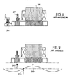
- FIG. 8 The majority of applications that use magnetic bearings are in accordance with the concept illustrated in FIG. 8. This concept corresponds to a clear separation of the various constituents and in particular a radial magnetic bearing 200, a radial position detector 201 and a radial position sensor 201. an axial position detector 301.
- the device comprises first and second radial detectors disposed respectively in the vicinity of a radial magnetic bearing and a conical magnetic bearing and extending around the rotor on an angular sector of 180 °.
- Such a device further comprises an axial detector extending around the rotor over an angular sector of at most 180 ° and disposed in the vicinity of the conical magnetic bearing substantially in the same radial plane as the second radial detector.
- the non-collocation that is to say the non-coincidence of the radial detection point 202 with the reaction point 203 of the radial bearing significantly complicates the definition of the control servitude.
- Deformations due to the mechanical design of the rotor can cause nodes 204 to be located between the radial bearing 200 and the radial detector 201, so that phase reversals occur between the detection and the reaction. which induces erroneous reactions on the part of the magnetic bearing.
- the present invention aims to overcome the aforementioned drawbacks and in particular to allow the reduction of the length of rotating machines, through the implementation of magnetic bearing assemblies more compact.
- Another object of the present invention is to avoid the non-coincidence of the detection and reaction points in an active magnetic suspension of a rotor.
- the first stack of ferromagnetic laminations of the stator comprises, successively in the axial direction, at least a first sub-phase. set of plates having first notches incorporating stator electromagnet windings, a second subset of laminations having both first notches incorporating stator electromagnet windings and second notches integrating a radial detector and a third subset of plates having first notches incorporating stator electromagnet windings, and in that the first stack of ferromagnetic laminations of the stator further comprises at its axial ends fourth and fifth sub-assemblies. sets of sheets each having the same notches respectively integrating first and second axial detectors.
- the detection of the position of the rotor by the position detectors coincides with the same point as the reaction of the active magnetic bearing.
- the second stack of rotor laminations extends over an axial length slightly greater than that of the first stack of stator laminations.
- the rotor comprises a non-magnetic solid ring located on each side of the second stack of rotor laminations.
- Non-magnetic rings can be steel, bronze or aluminum.
- each axial or radial position detector comprises a set of several detection elements.
- each axial or radial position detector comprises a set of four detection elements.
- the detection elements may be inductive type windings.
- the parallelism defects of the planes between the sheets of the second stack of sheets and the non-magnetic rings are averaged by placing in series the detection elements of each axial detector.
- the detection of the axial position is defined in the same place as the radial detection.
- the detection elements of an axial detector are mounted in bridge with the detection elements of the other axial detector.
- the oscillator frequency f d exciting the detectors is decoupled from the frequency f p of the current supplied to the magnetic bearing electromagnets.
- the decoupling is carried out by feeding the magnetic bearings through filters.
- the thickness of the sheets of the second stack of sheets is between 0.1 mm and 0.2 mm .
- the active magnetic bearing is of radial type.
- the active magnetic bearing is of conical type with radial and axial action.
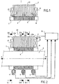
- FIG. 1 shows an example of a compact magnetic active bearing 1 according to the invention, with a radial magnetic flux, intended to equip a rotating machine.
- the magnetic bearing 1 comprises a stator 2 and a rotor 3 which are in relative rotational movement with respect to each other, the rotor 3 being able to be either inside or outside the stator 2.
- the stator 2 is equipped with solenoid coils 21, a stack of ferromagnetic sheets 22, a detector 6 of the radial position of the rotor 3, and two detectors 4 and 5 of the axial position of the rotor 3.
- rotor 3 is equipped with a stack of ferromagnetic plates 9 which extends over an axial length slightly greater than that of the stack of sheets 22 of the stator, two non-magnetic solid rings 7 and 8, each being located on each side of the stacking of sheets 9 of the rotor.
- the non-magnetic rings 7 and 8 can be for example steel, bronze or aluminum.
- the rotor 3 equipped with ferromagnetic sheets 9 is held by the magnetic fields created by the electromagnets arranged on the stator 2.
- the rotor 3 is thus in equilibrium without mechanical contact with the stator 2.
- Its position is identified by means of detectors 4, 5 and 6 preferably of inductive type, but may also be of any other type, which continuously record any displacements and which deliver signals allowing, through an electronic control loop, to control the currents in the electromagnet windings 21 so that the magnetic attraction forces return the rotor to its nominal position in case of displacement.
- the magnetic bearing comprises a stator yoke 2 provided with windings 21.
- the stator part 2 of the magnetic bearing cooperates with a ferromagnetic material reinforcement 9 of the rotor 3, mounted opposite the stator yoke 2 along the axis OO '.
- a single sheet stack is used with a thickness of between 0.1 mm and 0.2 mm with, for example, sheets of iron or silicon.
- the stack of rotor laminations is slightly wider than the stack of stator laminations, so as not to cause heating in the rotor by the radial bearing.
- the magnetic bearing also comprises a conventional axial magnetic stop which is not shown in Figure 2 but is controlled from the dual axial detector 4, 5 integrated in the radial bearing.
- the yoke of the stator part 2 is equipped with a stack of ferromagnetic sheets 22.
- the stack of ferromagnetic sheets of the stator comprises successively in the axial direction, five sets of sheets.
- a first set of sheets 2a incorporates solenoid windings 21 of the stator for the radial bearing function alone (FIG. 2A).
- a second set of sheets 2b incorporates solenoid windings 21 for the radial bearing function as well as a radial detector 6 (FIG. 28).
- a third set of sheets 2a is identical to the first set of sheets 2a and incorporates solenoid windings 21 of the stator for the radial bearing function alone (FIG. 2A).
- the ends of the stack of ferromagnetic sheets 22 of the stator 2 comprise fourth and fifth sets 2c of plates respectively integrating first 4 and second 5 axial detectors (Figure 2C) and located on either side of the central plate group comprising the first, second and third sets of sheets.
- the axial detectors 4, 5 and the radial detector 6 are of the inductive type, delivering signals from which the current in the windings of the radial magnetic bearing and the axial magnetic stop not shown, is controlled by means of a conventional control circuit 10.
- the purpose of the control circuit 10 is to control the position of the rotor 3 by acting on the current in the electromagnets from the signals delivered by the position detectors .
- the non-magnetic rings 7 and 8 located on each side of the sheet stack 9 of the rotor 3 serve as reference rings enabling the axial detectors 4 and 5 to accurately determine the axial position of the rotor 3 with respect to the assembly. 2. Indeed, the axial detectors 4 and 5 partially cooperate with the non-magnetic rings 7 and 8. Thus, during an axial displacement of the rotor 3, the partial overlaps of each of the non-magnetic rings 7, 8 and the 9 of the rotor 3 are different, so that the signals delivered by the axial detectors 4 and 5 are different and can provide information on the axial position of the rotor with a double precision to correctly enslave the axial stop for the maintaining a predetermined axial position. In a nominal axial position, the non-magnetic rings 7, 8 extend over half of the stack of fixed plates of the axial detectors 4 and 5 respectively.
- the radial detector 6 detects any variation of the gap, that is to say of the free space between the rotor 3 and the stator 2. The signal of the detector 6 is then compared by the servo-control circuit 10 to a signal reference unit defining the nominal position of the rotor 3, to correctly slave the radial bearing for maintaining a radial position in the center of the stator 2 along the axis 00 '.
- FIGS. 2A, 2B and 2C show the various blanks of the plates of the stator 2.
- Figure 2A shows a sheet 22a that can belong to the first or third set of sheets 2a.
- the plate 22a has a plurality of notches 70 incorporating windings of electromagnets 21 for the radial bearing function alone.
- Figure 2B shows a sheet 22b belonging to the second set of sheets 2b.
- the plate 22b has a plurality of notches 60 incorporating windings of electromagnets 21 for the radial bearing function along X and Y axes.
- Certain notches oriented along axes A and B interposed between the X and Y axes comprise additional teeth 61. , 62, 63 and 64, around which are winded detection windings 65, 66, 67 and 68, for the radial detector function.
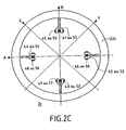
- FIG. 2C shows a sheet 22c belonging to the fourth or fifth set of sheets 2c, having a plurality of teeth 41, 42, 43, 44 or 51, 52, 53, 54 of the same shape, oriented along axes A and B interposed between the X and Y axes of the plates relative to the axes of action of the radial bearing.
- the set of plates having the teeth 41, 42, 43 and 44 and incorporating electromagnetic windings 45, 46, 47 and 48 respectively, represents the first axial detector 4, while the set of sheets having the teeth 51, 52, 53 and 54 and integrating electromagnetic windings 55, 56, 57 and 58 respectively, represents the second axial detector 5.
- the concerted inductive detection between the two detectors 4 and 5 provides an indication of the axial position of the rotor 3.
- the gain in length can be, for example, 34 mm on 157 mm, ie a gain about 22% at equivalent load.
- FIGS. 3 and 4 show a particular embodiment of a radial bearing according to the invention integrating axial detectors 4, 5 and a radial detector 6.
- Figure 5 shows the windings 65, 66, 67 and 68 of the radial detector 6 which are mounted in bridge.
- the windings 65 and 66 give the detection with suppression of even harmonics along the axis B.
- the windings 67 and 68 give the detection with deletion of even harmonics along the axis A.
- the detection along the X and Y axes of the bearing radial is obtained by the combination via the electronic control circuits of the control circuit 10.
- the windings 45, 46, 47 and 48 of the first axial detector 4 are connected in series, thus forming a first assembly, to average the parallelism defect of the sidewall of the non-magnetic ring against the plates of the armature of the rotor 3.
- a second set is formed of the series assembly of the windings 55, 56, 57 and 58 of the second axial sensor 5 located on the other side of the bearing.
- the first set is then mounted as a bridge with respect to the second set.
- This bridge assembly which doubles the detection sensitivity, also defines an axial virtual detection point located in the middle of the two axial detection rings, that is to say in the middle of the radial bearing at the same location as the radial detection.
- Integrating the axial sensors and the radial detector into the radial bearing could increase the risk of magnetic and electrical coupling between the detectors and the bearing.
- the frequency of the oscillator exciting the detectors f d 4, 5, 6 is decoupled from the frequency f p of the current supplied to the magnetic bearing electromagnets.
- the decoupling can be achieved by supplying the magnetic bearings via inductive-capacitive (LC) filters placed at the output of the amplifiers to avoid the high frequency of switching of the amplifiers. amplifiers in the metal mass of the bearing and thus avoid the couplings mentioned above.
- LC inductive-capacitive
- Figure 7 is an axial sectional view of an active magnetic bearing 101 according to a second embodiment of the invention.
- the active magnetic bearing 101 is a conical bearing with radial and axial action, where all the functions axial bearing, radial bearing, axial detector and radial detector are integrated in the same assembly.
- the magnetic bearing 101 comprises a conical-shaped stator yoke 102 provided with windings of electromagnets 121.
- the stator portion 102 of the magnetic bearing cooperates with a conical-shaped reinforcement of ferromagnetic material 109 of the rotor 103, mounted opposite the yoke stator 102 along the axis OO '.
- the conical shape of the magnetic bearing generates an axial component of the magnetic field in addition to the radial component and thus, an additional axial magnetic stop is no longer necessary.
- the yoke of the stator part 2 is equipped with a stack of conical ferromagnetic sheets 122.
- the stack of ferromagnetic laminations 122 of the stator comprises successively in the axial direction, five sets of sheets.
- a first set of plates incorporates solenoid windings 121 for the radial bearing function alone.
- a second set of plates incorporates solenoid windings 121 for the radial bearing function as well as a radial detector 106.
- a third set of plates incorporates solenoid windings 121 for the radial bearing function alone.
- the ends of the stack of ferromagnetic laminations 122 of the stator 102 comprise fourth and fifth sets of laminations respectively integrating first, 104, and second, 105 axial detectors.
- the axial detectors 104, 105 and the radial detector 106 deliver signals from which the current in the windings of the radial and axial magnetic bearing is controlled by means of the servocontrol circuit 110
- the non-magnetic rings 107 and 108 are conically shaped and located on each side of the sheet stack 109 of the rotor. These rings 107, 108 serve as reference rings enabling the axial detectors 104 and 105 to accurately determine the axial position of the rotor 103 with respect to the stator assembly 102.
- stator 102 Apart from the frustoconical shape of the walls of the stator 102 and the rotor 103 delimiting the gap and the fact that the bearing can directly react with the signals transmitted by the radial detector 106 and the axial detectors 104, 105 to the servocontrol circuit 110, the configuration of the stator 102 is similar to that of stator 2 of the bearing of FIG. 2 and the comments given with reference to FIGS. 2A, 2B, 2C and 3 to 6, also apply to the embodiment of FIG. 7.
Landscapes
- Engineering & Computer Science (AREA)
- General Engineering & Computer Science (AREA)
- Mechanical Engineering (AREA)
- Physics & Mathematics (AREA)
- General Physics & Mathematics (AREA)
- Electromagnetism (AREA)
- Magnetic Bearings And Hydrostatic Bearings (AREA)
Claims (17)
- Aktives Magnetlager (1; 101) mit radialem Magnetfluß für eine elektrische Maschine mit einer Drehachse OO', wobei das Magnetlager (1; 101) einen Stator (2; 102), der mit Elektromagnetspulen (21; 121) und einem ersten Stapel von ferromagnetischen Blechen (22, 122), die im Wesentlichen zur Achse OO' senkrecht sind, ausgestattet ist, einen Rotor (3; 103), der mit einem zweiten Stapel von ferromagnetischen Blechen (9; 109), die im Wesentlichen zur Drehachse OO' senkrecht sind, ausgestattet ist, Steuerschaltungen (10; 110), um den Rotor (3; 103) ohne Kontakt mit dem Stator (2; 102) im Gleichgewicht zu halten, und mindestens einen Detektor für die radiale Position (6; 106) des Rotors und mindestens einen Detektor für die axiale Position (4, 5; 104, 105) des Rotors umfaßt, wobei die Detektoren für die radiale Position und für die axiale Position an die Steuerschaltungen (10; 110) Signale liefern, auf deren Basis der Strom in den Elektromagneten (21; 121) des Stators (2; 102) gesteuert wird;
dadurch gekennzeichnet, daß der erste Stapel von ferromagnetischen Blechen (22; 122) des Stators (2; 102) nacheinander in Axialrichtung mindestens eine Untereinheit (2a) von Blechen (22a), die erste Kerben (70) aufweisen, die Wicklungen (21; 121) eines Elektromagneten des Stators (2; 102) besitzen, eine zweite Untereinheit (2b) von Blechen (22b), die sowohl erste Kerben (60), die Wicklungen eines Elektromagneten (21; 121) des Stators (2; 102) besitzen, als auch zweite Kerben aufweisen, die einen Radialdetektor (6; 106) besitzen, und eine dritte Untereinheit (2a) von Blechen (22a) umfaßt, die erste Kerben (70), die Wicklungen eines Elektromagneten (21; 121) des Stators (2; 102) besitzen, und daß der erste Stapel von ferromagnetischen Blechen (22; 122) des Stators (2; 102) ferner an seinen Axialenden vierte und fünfte Untereinheiten (2c) von Blechen (22c) umfaßt, die jeweils selbe Kerben aufweisen, die erste bzw. zweite Axialdetektoren (4, 5; 104, 105) besitzen. - Magnetlager (1, 101) nach Anspruch 1, dadurch gekennzeichnet, daß die Erfassung der Position des Rotors (3; 103) durch die Positionsdetektoren (4, 5, 6; 104, 105, 106) an demselben Punkt wie die Reaktion des aktiven Magnetlagers (1; 101) erfolgt.
- Magnetlager (1, 101) nach Anspruch 2, dadurch gekennzeichnet, daß sich der zweite Blechstapel (9; 109) des Rotors auf einer etwas größeren Axiallänge als jene des ersten Blechstapels (22; 122) des Stators erstreckt.
- Magnetlager (1; 101 nach einem der Ansprüche 1 bis 3, dadurch gekennzeichnet, daß der Rotor (3; 103) einen nicht magnetischen massiven Ring (7, 8; 107, 108) umfaßt, der sich auf jeder Seite des zweiten Blechstapels (9; 109) des Rotors befindet.
- Magnetlager (1; 101) nach Anspruch 4, dadurch gekennzeichnet, daß die nicht magnetischen Ringe (7, 8; 107, 108) aus Stahl, Bronze oder Aluminium bestehen.
- Magnetlager (1; 101) nach einem der Ansprüche 1 bis 5, dadurch gekennzeichnet, daß jeder Detektor einer Axial- oder Radialposition (4, 5, 6; 104, 105, 106) einen Satz von mehreren Erfassungselementen umfaßt.
- Magnetlager (1; 101) nach einem der Ansprüche 1 bis 6, dadurch gekennzeichnet, daß jeder Detektor einer Axial- oder Radialposition (4, 5, 6; 104, 105, 106) einen Satz von vier Erfassungselementen (45, 46, 47, 48) oder (55, 56, 57, 48) oder (65, 66, 67, 68) umfaßt.
- Magnetlager (1, 101) nach einem der Ansprüche 6 und 7, dadurch gekennzeichnet, daß die Erfassungselemente Wicklungen induktiven Typs sind.
- Magnetlager (1; 101) nach Anspruch 4 und einem der Ansprüche 6 bis 8, dadurch gekennzeichnet, daß die Parallelitätsfehler der Ebenen zwischen den Blechen des zweiten Blechstapels (9; 109) und den nicht magnetischen Ringen (7, 8; 107, 108) dank der seriellen Anordnung der Erfassungselemente (45, 46, 47, 48) oder (55, 56, 57, 58) jedes Axialdetektors (4, 5) ausgeglichen werden.
- Magnetlager (1; 101) nach einem der Ansprüche 1 bis 9, dadurch gekennzeichnet, daß die Erfassung der Axialposition an derselben Stelle wie die Radialposition definiert ist.
- Magnetlager (1; 101) nach Anspruch 10, dadurch gekennzeichnet, daß die Erfassungselemente (45, 46, 47, 48) eines Axialdetektors (4) mit den Erfassungselementen (55, 56, 57, 58) des anderen Axialdetektors (5) in Brücke geschaltet sind.
- Magnetlager (1; 101) nach einem der Ansprüche 1 bis 11, dadurch gekennzeichnet, daß die Frequenz des Oszillators fd, der die Detektoren (4, 5, 6; 104, 105, 106) erregt, von der Frequenz fp des Stroms, der die Elektromagneten des Magnetlagers speist, entkoppelt ist.
- Magnetlager (1; 101) nach Anspruch 12, dadurch gekennzeichnet, daß die Entkopplung verwirklicht ist, wobei die Erregerfrequenz fd der Detektoren und die Speisefrequenz fp der Elektromagneten des Magnetlagers in einem Verhältnis von 1 zu 2 synchronisiert werden, so daß fd = fp/2.
- Magnetlager (1; 101) nach Anspruch 12 oder Anspruch 13, dadurch gekennzeichnet, daß die Entkopplung durch Speisen der Magnetlager durch Filter verwirklicht ist.
- Magnetlager (1; 101) nach einem der Ansprüche 1 bis 14, dadurch gekennzeichnet, daß die Dicke der Bleche des zweiten Blechstapels (9; 109) zwischen 0,1 mm und 0,2 mm beträgt.
- Magnetlager (1; 101) nach einem der Ansprüche 1 bis 15, dadurch gekennzeichnet, daß das aktive Magnetlager vom radialen Typ (1) ist.
- Magnetlager (1; 101) nach einem der Ansprüche 1 bis 15, dadurch gekennzeichnet, daß das aktive Magnetlager vom konischen Typ (101) mit radialer und axialer Wirkung ist.
Applications Claiming Priority (3)
| Application Number | Priority Date | Filing Date | Title |
|---|---|---|---|
| FR0107914A FR2826077B1 (fr) | 2001-06-15 | 2001-06-15 | Palier magnetique actif a detecteurs integres |
| FR0107914 | 2001-06-15 | ||
| PCT/FR2002/002022 WO2002103216A1 (fr) | 2001-06-15 | 2002-06-13 | Palier magnetique actif a detecteurs integres |
Publications (2)
| Publication Number | Publication Date |
|---|---|
| EP1395759A1 EP1395759A1 (de) | 2004-03-10 |
| EP1395759B1 true EP1395759B1 (de) | 2006-03-08 |
Family
ID=8864399
Family Applications (1)
| Application Number | Title | Priority Date | Filing Date |
|---|---|---|---|
| EP02745522A Expired - Lifetime EP1395759B1 (de) | 2001-06-15 | 2002-06-13 | Aktives magnetlager mit integrierten sensoren |
Country Status (6)
| Country | Link |
|---|---|
| US (1) | US6849979B2 (de) |
| EP (1) | EP1395759B1 (de) |
| JP (1) | JP4184950B2 (de) |
| DE (1) | DE60209728T2 (de) |
| FR (1) | FR2826077B1 (de) |
| WO (1) | WO2002103216A1 (de) |
Cited By (1)
| Publication number | Priority date | Publication date | Assignee | Title |
|---|---|---|---|---|
| DE102011005761A1 (de) | 2011-03-18 | 2012-09-20 | Schaeffler Technologies Gmbh & Co. Kg | Lageranordnung mit einem Fanglager |
Families Citing this family (32)
| Publication number | Priority date | Publication date | Assignee | Title |
|---|---|---|---|---|
| US20050264118A1 (en) * | 2004-03-01 | 2005-12-01 | Kascak Peter E | Conical bearingless motor/generator |
| US7456537B1 (en) | 2004-12-17 | 2008-11-25 | The University Of Toledo | Control system for bearingless motor-generator |
| US20060238053A1 (en) * | 2004-03-01 | 2006-10-26 | The University Of Toledo | Conical bearingless motor/generator |
| CN1667418B (zh) * | 2004-03-10 | 2010-10-06 | 马杰 | 多功能测量、分析和诊断便携式装置 |
| GB0419152D0 (en) * | 2004-08-27 | 2004-09-29 | Kernow Instr Technology Ltd | A contactless magnetic rotary bearing and a rheometer incorporating such bearing |
| DE102005030878B4 (de) * | 2005-07-01 | 2010-09-02 | Siemens Ag | Vorrichtung und Verfahren zur Erfassung der Mittenabweichung einer Welle |
| DE102005032675A1 (de) * | 2005-07-13 | 2007-01-25 | Renk Ag | Aktives Magnetlager mit integrierter Wegsensorik |
| FR2897911B1 (fr) * | 2006-02-27 | 2009-03-27 | Mecanique Magnetique Sa Soc D | Palier magnetique actif chemise |
| US20080084139A1 (en) * | 2006-10-04 | 2008-04-10 | Emerson Electric Co. | Motor having rotor position sensor |
| AT505598B1 (de) * | 2006-12-19 | 2015-05-15 | Manfred Dipl Ing Dr Schrödl | Magnetlagereinrichtung |
| SG189798A1 (en) * | 2008-04-17 | 2013-05-31 | Synchrony Inc | High-speed permanent magnet motor and generator with low-loss metal rotor |
| WO2009140022A2 (en) | 2008-04-18 | 2009-11-19 | Ramsey Gary S | Magnetic thrust bearing with integrated electronics |
| DE102008046357A1 (de) * | 2008-09-09 | 2010-03-11 | Schaeffler Kg | Sensoranordnung zur Bestimmung einer Kenngröße für den Verschleiß eines Wälzlagers und Windkraftanlage |
| ES2349816B1 (es) | 2009-05-13 | 2011-11-14 | Industria De Turbo Propulsores, S.A. | Sistema de medida de la posicion axial de ejes. |
| US9583991B2 (en) * | 2009-06-24 | 2017-02-28 | Synchrony, Inc. | Systems, devices, and/or methods for managing magnetic bearings |
| EP2357374B1 (de) * | 2010-01-29 | 2016-02-17 | Levitronix GmbH | Magnetische Lagervorrichtung |
| KR101159054B1 (ko) * | 2010-03-03 | 2012-06-25 | 주식회사 디엔엠 테크놀로지 | 능동형 자기 베어링 |
| US20110291532A1 (en) * | 2010-05-26 | 2011-12-01 | Seiko Epson Corporation | Coreless electromechanical device |
| EP2586121B1 (de) | 2010-06-23 | 2019-12-11 | Synchrony, Inc. | Geteiltes magnetisches axialdrucklager |
| FR2963154B1 (fr) | 2010-07-23 | 2013-07-19 | Mecanique Magnetique Sa | Appareil electrique a connexions etanches et procede de fabrication |
| FR2994021B1 (fr) | 2012-07-27 | 2014-08-22 | Mecanique Magnetique Sa | Connecteur electrique etanche pour paliers magnetiques |
| EP2885854B1 (de) * | 2012-09-26 | 2019-03-20 | Siemens Aktiengesellschaft | Radialmagnetlager und verfahren zur herstellung eines radialmagnetlagers |
| US9657744B2 (en) | 2013-02-13 | 2017-05-23 | Dresser-Rand Company | Midspan active magnetic bearing |
| EP2887022B1 (de) | 2013-12-20 | 2016-09-07 | Skf Magnetic Mechatronics | Drehmessaufnehmerziel für Magnetlager |
| EP3026277B1 (de) * | 2014-11-27 | 2023-04-26 | Skf Magnetic Mechatronics | Magnetlager, vorrichtung mit solch einem magnetlager und verfahren zur herstellung solch eines magnetlagers |
| EP3026278B1 (de) * | 2014-11-27 | 2020-03-18 | Skf Magnetic Mechatronics | Magnetlager, rotierende Vorrichtung mit solch einem Magnetlager und Verfahren zur Herstellung solch eines Magnetlagers |
| JP6793445B2 (ja) * | 2015-07-07 | 2020-12-02 | エドワーズ株式会社 | 電磁石ユニット、磁気軸受装置及び真空ポンプ |
| EP3141870B1 (de) | 2015-09-09 | 2019-08-14 | Skf Magnetic Mechatronics | Radialer positionssensor |
| EP3203191A1 (de) * | 2016-02-03 | 2017-08-09 | Siemens Aktiengesellschaft | Sensor für ein magnetlager |
| DE102016219596A1 (de) * | 2016-10-10 | 2018-04-12 | Siemens Aktiengesellschaft | Magnetlageranordnung |
| DE102017208978A1 (de) | 2017-05-29 | 2018-11-29 | Siemens Aktiengesellschaft | Magnetlageranordnung |
| CN115045914B (zh) * | 2022-06-30 | 2023-10-31 | 中国铁建重工集团股份有限公司 | 一种不接触式回转支承 |
Family Cites Families (12)
| Publication number | Priority date | Publication date | Assignee | Title |
|---|---|---|---|---|
| FR2094326A5 (de) | 1970-06-17 | 1972-02-04 | Habermann Helmut | |
| US4088379A (en) * | 1974-09-18 | 1978-05-09 | Perper Lloyd J | Variable permanent magnet suspension system |
| JPS5881217A (ja) * | 1981-11-11 | 1983-05-16 | Seiko Instr & Electronics Ltd | 5自由度制御形磁気軸受装置 |
| JPS60245443A (ja) * | 1984-05-18 | 1985-12-05 | Ntn Toyo Bearing Co Ltd | 制御式ラジアル磁気軸受装置 |
| US4634191A (en) * | 1985-11-21 | 1987-01-06 | The United States Of America As Represented By The Administrator Of The National Aeronautics & Space Administration | Radial and torsionally controlled magnetic bearing |
| FR2632451B1 (fr) | 1988-06-06 | 1990-09-28 | Mecanique Magnetique Sa | Tube a rayons x a anode rotative montee sur une suspension magnetique |
| DE68925510T2 (de) * | 1988-10-21 | 1996-08-29 | Ebara Corp | Magnetlagersystem |
| US5053662A (en) * | 1990-04-18 | 1991-10-01 | General Electric Company | Electromagnetic damping of a shaft |
| DE4022523A1 (de) * | 1990-07-16 | 1992-01-23 | Pfeiffer Vakuumtechnik | Einrichtung zum fluten von schnell rotierenden vakuumpumpen |
| US5319273A (en) * | 1992-10-26 | 1994-06-07 | Satcon Technology Corporation | Fixed gain electromagnetic actuator and electromagnetic bearing incorporating same |
| US5572079A (en) * | 1994-12-21 | 1996-11-05 | Magnetic Bearing Technologies, Inc. | Magnetic bearing utilizing brushless generator |
| FR2768470B1 (fr) * | 1997-09-12 | 2002-02-01 | Mecanique Magnetique Sa | Pompe rotative a rotor immerge |
-
2001
- 2001-06-15 FR FR0107914A patent/FR2826077B1/fr not_active Expired - Lifetime
-
2002
- 2002-06-13 DE DE60209728T patent/DE60209728T2/de not_active Expired - Fee Related
- 2002-06-13 WO PCT/FR2002/002022 patent/WO2002103216A1/fr active IP Right Grant
- 2002-06-13 US US10/480,605 patent/US6849979B2/en not_active Expired - Lifetime
- 2002-06-13 EP EP02745522A patent/EP1395759B1/de not_active Expired - Lifetime
- 2002-06-13 JP JP2003505499A patent/JP4184950B2/ja not_active Expired - Lifetime
Cited By (2)
| Publication number | Priority date | Publication date | Assignee | Title |
|---|---|---|---|---|
| DE102011005761A1 (de) | 2011-03-18 | 2012-09-20 | Schaeffler Technologies Gmbh & Co. Kg | Lageranordnung mit einem Fanglager |
| WO2012126743A1 (de) | 2011-03-18 | 2012-09-27 | Schaeffler Technologies AG & Co. KG | Lageranordnung mit einem fanglager |
Also Published As
| Publication number | Publication date |
|---|---|
| US6849979B2 (en) | 2005-02-01 |
| FR2826077B1 (fr) | 2003-09-19 |
| US20040164632A1 (en) | 2004-08-26 |
| WO2002103216A1 (fr) | 2002-12-27 |
| DE60209728D1 (de) | 2006-05-04 |
| FR2826077A1 (fr) | 2002-12-20 |
| EP1395759A1 (de) | 2004-03-10 |
| JP2004522111A (ja) | 2004-07-22 |
| JP4184950B2 (ja) | 2008-11-19 |
| DE60209728T2 (de) | 2006-11-23 |
Similar Documents
| Publication | Publication Date | Title |
|---|---|---|
| EP1395759B1 (de) | Aktives magnetlager mit integrierten sensoren | |
| WO1990016107A1 (fr) | Actionneur electromagnetique monophase de faible encombrement | |
| EP2182230B1 (de) | Axiales Magnetlager mit Verkleidung | |
| EP1808609A1 (de) | Magnetlageranordnung eines Rotors mit einem elektromagnetischen Axiallager | |
| WO2000052425A1 (fr) | Capteur de position a sonde magneto-sensible | |
| FR2609123A1 (fr) | Palier fluide hybride a raideur modifiee par effet electromagnetique | |
| FR2971826A1 (fr) | Dispositif tournant notamment pour volant d'inertie | |
| EP0214896B1 (de) | Radiales Magnetlager mit grossem Durchmesser | |
| EP1727998B1 (de) | Aktives magnetlager mit automatischer erfassung von dessen position | |
| EP0642704B1 (de) | Drehendes elektromagnetisches einphasenbetätigungsorgan | |
| EP2156538B1 (de) | Elektromagnetischer aktor mit variabler reluktanz | |
| EP3522334A1 (de) | Magnetschaltkreis für element einer elektrisch umlaufenden maschine, entsprechendes verfahren und entsprechende elektrische maschine | |
| WO2001040736A1 (fr) | Capteur analogique de decalage angulaire sans contact | |
| FR2876228A1 (fr) | Rotor pour moteur electrique et moteur electrique correspondant | |
| EP2511665B1 (de) | Vorrichtung zur axialen Positionserfassung einer Drehwelle, und Verwendung in einer Turbomolekularpumpe | |
| EP2813904B1 (de) | Elektronisches Uhrwerk, das einen Uhrenmotor umfasst | |
| FR2977090A1 (fr) | Rotor de moteur electrique | |
| FR2977740A1 (fr) | Rotor de moteur electrique comprenant un arbre frette dans un empilement de toles, et procede de fabrication du rotor | |
| WO2023105149A1 (fr) | Dispositif de mesure de l'oxydation d'un disque de frein par mesure de diamagnétisme | |
| EP0890033A1 (de) | Bewegungsfeststellunganordnung eines auf aktiven magnetlagern aufgebauten rotors | |
| FR2853159A1 (fr) | Ralentisseur electromagnetique d'un vehicule | |
| EP4202564A1 (de) | Mechanisches uhrwerk mit einer magnetisch schwenkbaren unruh | |
| FR3110773A1 (fr) | Ensemble électrochimique, batterie et procédé correspondants | |
| FR3090860A1 (fr) | Rotor pour capteur inductif de déplacement angulaire | |
| CH719302A2 (fr) | Mécanisme comprenant un élément rotatif, notamment un balancier horloger, et un dispositif magnétique de guidage en rotation de cet élément rotatif. |
Legal Events
| Date | Code | Title | Description |
|---|---|---|---|
| PUAI | Public reference made under article 153(3) epc to a published international application that has entered the european phase |
Free format text: ORIGINAL CODE: 0009012 |
|
| 17P | Request for examination filed |
Effective date: 20031202 |
|
| AK | Designated contracting states |
Kind code of ref document: A1 Designated state(s): AT BE CH CY DE DK ES FI FR GB GR IE IT LI LU MC NL PT SE TR |
|
| GRAP | Despatch of communication of intention to grant a patent |
Free format text: ORIGINAL CODE: EPIDOSNIGR1 |
|
| GRAS | Grant fee paid |
Free format text: ORIGINAL CODE: EPIDOSNIGR3 |
|
| GRAA | (expected) grant |
Free format text: ORIGINAL CODE: 0009210 |
|
| AK | Designated contracting states |
Kind code of ref document: B1 Designated state(s): CH DE GB IT LI SE |
|
| REG | Reference to a national code |
Ref country code: GB Ref legal event code: FG4D Free format text: NOT ENGLISH |
|
| REG | Reference to a national code |
Ref country code: CH Ref legal event code: EP |
|
| REF | Corresponds to: |
Ref document number: 60209728 Country of ref document: DE Date of ref document: 20060504 Kind code of ref document: P |
|
| REG | Reference to a national code |
Ref country code: CH Ref legal event code: NV Representative=s name: MICHELI & CIE INGENIEURS-CONSEILS |
|
| REG | Reference to a national code |
Ref country code: SE Ref legal event code: TRGR |
|
| GBT | Gb: translation of ep patent filed (gb section 77(6)(a)/1977) |
Effective date: 20060612 |
|
| PLBE | No opposition filed within time limit |
Free format text: ORIGINAL CODE: 0009261 |
|
| STAA | Information on the status of an ep patent application or granted ep patent |
Free format text: STATUS: NO OPPOSITION FILED WITHIN TIME LIMIT |
|
| 26N | No opposition filed |
Effective date: 20061211 |
|
| PGFP | Annual fee paid to national office [announced via postgrant information from national office to epo] |
Ref country code: SE Payment date: 20070521 Year of fee payment: 6 |
|
| PGFP | Annual fee paid to national office [announced via postgrant information from national office to epo] |
Ref country code: DE Payment date: 20070612 Year of fee payment: 6 |
|
| PGFP | Annual fee paid to national office [announced via postgrant information from national office to epo] |
Ref country code: CH Payment date: 20070613 Year of fee payment: 6 |
|
| PGFP | Annual fee paid to national office [announced via postgrant information from national office to epo] |
Ref country code: GB Payment date: 20070612 Year of fee payment: 6 |
|
| PGFP | Annual fee paid to national office [announced via postgrant information from national office to epo] |
Ref country code: IT Payment date: 20080623 Year of fee payment: 7 |
|
| REG | Reference to a national code |
Ref country code: CH Ref legal event code: PL |
|
| EUG | Se: european patent has lapsed | ||
| GBPC | Gb: european patent ceased through non-payment of renewal fee |
Effective date: 20080613 |
|
| PG25 | Lapsed in a contracting state [announced via postgrant information from national office to epo] |
Ref country code: DE Free format text: LAPSE BECAUSE OF NON-PAYMENT OF DUE FEES Effective date: 20090101 |
|
| PG25 | Lapsed in a contracting state [announced via postgrant information from national office to epo] |
Ref country code: CH Free format text: LAPSE BECAUSE OF NON-PAYMENT OF DUE FEES Effective date: 20080630 Ref country code: GB Free format text: LAPSE BECAUSE OF NON-PAYMENT OF DUE FEES Effective date: 20080613 Ref country code: LI Free format text: LAPSE BECAUSE OF NON-PAYMENT OF DUE FEES Effective date: 20080630 |
|
| PG25 | Lapsed in a contracting state [announced via postgrant information from national office to epo] |
Ref country code: SE Free format text: LAPSE BECAUSE OF NON-PAYMENT OF DUE FEES Effective date: 20080614 |
|
| PG25 | Lapsed in a contracting state [announced via postgrant information from national office to epo] |
Ref country code: IT Free format text: LAPSE BECAUSE OF NON-PAYMENT OF DUE FEES Effective date: 20090613 |