EP1394888A1 - Electrolyte solution for secondary battery and secondary battery using the same - Google Patents
Electrolyte solution for secondary battery and secondary battery using the same Download PDFInfo
- Publication number
- EP1394888A1 EP1394888A1 EP03090268A EP03090268A EP1394888A1 EP 1394888 A1 EP1394888 A1 EP 1394888A1 EP 03090268 A EP03090268 A EP 03090268A EP 03090268 A EP03090268 A EP 03090268A EP 1394888 A1 EP1394888 A1 EP 1394888A1
- Authority
- EP
- European Patent Office
- Prior art keywords
- secondary battery
- electrolyte solution
- group
- battery according
- compound
- Prior art date
- Legal status (The legal status is an assumption and is not a legal conclusion. Google has not performed a legal analysis and makes no representation as to the accuracy of the status listed.)
- Granted
Links
Images


Classifications
-
- H—ELECTRICITY
- H01—ELECTRIC ELEMENTS
- H01M—PROCESSES OR MEANS, e.g. BATTERIES, FOR THE DIRECT CONVERSION OF CHEMICAL ENERGY INTO ELECTRICAL ENERGY
- H01M10/00—Secondary cells; Manufacture thereof
- H01M10/05—Accumulators with non-aqueous electrolyte
- H01M10/056—Accumulators with non-aqueous electrolyte characterised by the materials used as electrolytes, e.g. mixed inorganic/organic electrolytes
- H01M10/0564—Accumulators with non-aqueous electrolyte characterised by the materials used as electrolytes, e.g. mixed inorganic/organic electrolytes the electrolyte being constituted of organic materials only
- H01M10/0566—Liquid materials
- H01M10/0567—Liquid materials characterised by the additives
-
- H—ELECTRICITY
- H01—ELECTRIC ELEMENTS
- H01M—PROCESSES OR MEANS, e.g. BATTERIES, FOR THE DIRECT CONVERSION OF CHEMICAL ENERGY INTO ELECTRICAL ENERGY
- H01M10/00—Secondary cells; Manufacture thereof
- H01M10/05—Accumulators with non-aqueous electrolyte
- H01M10/052—Li-accumulators
-
- H—ELECTRICITY
- H01—ELECTRIC ELEMENTS
- H01M—PROCESSES OR MEANS, e.g. BATTERIES, FOR THE DIRECT CONVERSION OF CHEMICAL ENERGY INTO ELECTRICAL ENERGY
- H01M10/00—Secondary cells; Manufacture thereof
- H01M10/05—Accumulators with non-aqueous electrolyte
- H01M10/052—Li-accumulators
- H01M10/0525—Rocking-chair batteries, i.e. batteries with lithium insertion or intercalation in both electrodes; Lithium-ion batteries
-
- H—ELECTRICITY
- H01—ELECTRIC ELEMENTS
- H01M—PROCESSES OR MEANS, e.g. BATTERIES, FOR THE DIRECT CONVERSION OF CHEMICAL ENERGY INTO ELECTRICAL ENERGY
- H01M10/00—Secondary cells; Manufacture thereof
- H01M10/42—Methods or arrangements for servicing or maintenance of secondary cells or secondary half-cells
- H01M10/4235—Safety or regulating additives or arrangements in electrodes, separators or electrolyte
-
- H—ELECTRICITY
- H01—ELECTRIC ELEMENTS
- H01M—PROCESSES OR MEANS, e.g. BATTERIES, FOR THE DIRECT CONVERSION OF CHEMICAL ENERGY INTO ELECTRICAL ENERGY
- H01M2300/00—Electrolytes
- H01M2300/0017—Non-aqueous electrolytes
- H01M2300/0025—Organic electrolyte
- H01M2300/0028—Organic electrolyte characterised by the solvent
- H01M2300/0037—Mixture of solvents
- H01M2300/004—Three solvents
-
- Y—GENERAL TAGGING OF NEW TECHNOLOGICAL DEVELOPMENTS; GENERAL TAGGING OF CROSS-SECTIONAL TECHNOLOGIES SPANNING OVER SEVERAL SECTIONS OF THE IPC; TECHNICAL SUBJECTS COVERED BY FORMER USPC CROSS-REFERENCE ART COLLECTIONS [XRACs] AND DIGESTS
- Y02—TECHNOLOGIES OR APPLICATIONS FOR MITIGATION OR ADAPTATION AGAINST CLIMATE CHANGE
- Y02E—REDUCTION OF GREENHOUSE GAS [GHG] EMISSIONS, RELATED TO ENERGY GENERATION, TRANSMISSION OR DISTRIBUTION
- Y02E60/00—Enabling technologies; Technologies with a potential or indirect contribution to GHG emissions mitigation
- Y02E60/10—Energy storage using batteries
Definitions
- the present invention relates to an electrolyte solution for a secondary battery and a secondary battery using the electrolyte solution.
- a non-aqueous electrolyte lithium ion secondary battery or a non-aqueous electrolyte lithium secondary battery having an anode made of a carbon material, an oxide, a lithium alloy or metallic lithium is attracting attention as electric power source for cell phones or notebook computers, since the use of such battery provides higher energy density.
- a film which is referred to as surface film, protection film, solid electrolyte interface (SEI) or coating layer (hereinafter generically referred to as surface film), is formed on the surface of the anode of such type of secondary battery. Since the surface film affects the efficiency of electrical charging and discharging, the cycle life and the safety of the secondary battery, it is known that controlling the formation of the surface film is essential for achieving higher performances of the anode. When carbon materials or oxides are employed for the anode, the irreversible capacity of these materials must be reduced. When the metallic lithium anode or the lithium alloy anode is employed, the problems of lower efficiency of electrical charging and discharging or the problems of lower safety due to the formation of dendrite crystal (tree branch-shaped crystal) must be solved.
- dendrite can be inhibited by forming a coating layer comprising lithium fluoride or the like on the metallic lithium substrate or the lithium alloy surface via chemical reaction.
- JP-A-H7-302,617 is disclosed a technique of coating the surface of the lithium anode with a lithium fluoride film by exposing the lithium anode to an electrolyte solution containing hydrofluoric acid thereby reacting the anode surface with hydrofluoric acid.
- Hydrofluoric acid is generated by a reaction between LiPF 6 and a slight amount of water.
- a surface film of native lithium hydroxide or native lithium oxide is formed on the lithium anode surface via natural oxidation in atmospheric condition.
- the surface film of lithium fluoride is formed on the anode surface by reacting the native oxide or hydroxide film and the hydrofluoric acid.
- the lithium fluoride film is obtainable via the reaction between the anode interface and the solution, it is difficult to obtain a uniform lithium fluoride film, as the surface film is easily contaminated with the reaction byproducts generated during the reaction.
- the surface film of native lithium hydroxide or native lithium oxide is not uniformly formed, the surface film may partially include bare lithium surfaces. In such case, a uniform thin film of lithium fluoride is not obtainable, and further serious safety problems of possibly reacting the bare lithium surface with water or hydrogen fluoride may be caused.
- unwanted other products than fluorides may remain in the surface film, thereby possibly causing harmful effects such as deterioration of ion conductivity.
- the availability of fluorides and electrolyte solutions is strictly limited, thereby making it difficult to form a stable surface film with higher process yield.
- JP-A-H8-250,108 is disclosed a technique of forming a surface film of lithium fluoride on the anode surface by causing a reaction between a gaseous mixture of argon and hydrogen fluoride and an aluminum-lithium alloy.
- a surface film of other material in particular a surface film of a plurality of chemical compounds, already exists on the metallic lithium surface before forming the surface film of lithium fluoride thereon, reaction tends to proceed non-uniformly, so that it is difficult to form a uniform film of lithium fluoride. For this reason, it is difficult to obtain a lithium secondary battery having sufficient cycle properties.
- JP-A-H11-288,706 is disclosed a technique of forming a surface coating structure comprising a material having rock-salt structure as a main component on a surface of a lithium sheet having a uniform crystal structure, i.e., [100] crystalline plane is preferentially oriented. It is also disclosed that this technique provides uniform deposition-dissolution reaction thereof, that is, uniform charging and discharging of the battery, so that the dendrite deposition is inhibited to improve the cycle life of the battery. It is further disclosed that the materials for the surface film preferably include halides of lithium, and more preferably include a solid solution of LiF and at least one selected from the group consisting of LiCl, LiBr and LiI.
- an anode for non-aqueous electrolyte battery is manufactured by dipping a lithium sheet having preferentially oriented [100] crystalline plane and being manufactured via a metal pressuring (flat rolling) process into an electrolyte solution containing fluorine molecule or fluorine ion and at least one selected from the group consisting of chlorine molecule or chlorine ion, bromine molecule or bromine ion and iodine molecule or iodine ion, in order to form the solid solution coating of LiF and at least one selected from the group consisting of LiCl, LiBr and LiI.
- This technique cannot sufficiently prevent the formation of dendrite deposition, since the lithium sheet used in this technique is manufactured via flat rolling process, in which the lithium sheet may be exposed to air atmosphere so that the native surface coatings derived by moisture and the like may easily be formed partially on the surface of the lithium sheet during the process, thereby non-uniformly distributing the active areas across the surface of the sheet, and it being difficult to form the targeted stable surface film.
- NAOI et al. disclose in the 68th Annual Meeting of The Electrochemical Society of Japan (September 2000, at CHIBA INSTITUTE OF TECHNOLOGY, Number of presentation; 2A24), and The 41 st Battery Symposium in Japan (November 2000, at NAGOYA INTERNATIONAL CONFERENCE HALL, Number of presentation; 1E03) the influence of the complex of lanthanoid transition metals such as europium or the like and imide anion on the metallic lithium anode.
- an electrolyte solution is prepared by dissolving a lithium salt of LiN(C 2 F 5 SO 2 ) 2 into a mixed solvent of propylene carbonate or ethylene carbonate and 1,2-diethoxymethane, and further adding an additive of Eu(CF 3 SO 3 ) 3 , and a surface film of Eu[(C 2 F 5 SO 2 ) 2 ] 2 complex is formed on a Li metal surface that is dipped in this electrolyte solution.
- This method is effective in improving the cycle life in a certain level, but not sufficient.
- this method requires a relatively expensive lithium imide salt such as LiN(C 2 F 5 SO 2 ) 2 .
- Lithium imide salts cannot be employed for this method, since the complex of transition metal and imide anion is not formed when adding the complex of other lithium salts (e.g., typically LiPF 6 ) transition metal and CF 3 SO 3 - F 3 S ion, and thus the cycle properties cannot be improved. Further, the use of lithium imide salts as electrolyte solution provides higher resistance of the electrolyte solution than the use of LiPF 6 and the like, thereby causing a problem of increasing the internal resistance of the battery.
- other lithium salts e.g., typically LiPF 6
- JP-A-H5-234,583 an anode comprising a carbon material that is coated with aluminum is proposed.
- This configuration inhibits reductional decomposition of solvent molecules that solvate with lithium ion, so that the degradation of the cycle life can be prevented.
- aluminum reacts with a slight amount of water, thereby causing a problem of rapidly decreasing the electrical capacity of the battery when cycles are repeated.
- an anode comprising a carbon material, the surface of which is coated with a thin film of lithium ion-conductive solid electrolyte.
- This configuration inhibits decomposition of the solvent that has occurred due to the use of the carbon material, and in particular, this configuration can provide a lithium ion secondary battery that is capable of using propylene carbonate.
- cracks are generated in the solid electrolyte due to the stress variation when lithium ion is inserted and desorbed, and the cracks lead to the deterioration of the properties thereof.
- the quality of the solid electrolyte is not uniform due to the crystalline defects contained therein, and a non-uniformity of the quality leads to non-uniform reaction across the surface of the anode, thereby deteriorating the cycle life.
- JP-A-2000-3,724 is disclosed a secondary battery comprising: an anode comprising a material including graphite; an electrolyte solution containing a main component of cyclic carbonate and linear carbonate, and an electrolyte solution additionally containing 0.1 %wt. to 4 % wt. of 1,3-propanesultone and/or 1,4-butanesultone.
- the active and highly crystallized carbon material such as natural graphite or artificial graphite is coated with this type of passivating coating to provide an advantageous effect of inhibiting the degradation of the electrolyte solution without deteriorating the ordinal chemical reaction for the battery.
- this method does not provide a sufficient coating effect, such that the electrical charge generated by decomposition of solvent molecule or anion appears as an irreversible electrical capacity component, thereby decreasing the initial charge-discharge efficiency.
- the resistance of the thus formed coating is high, and in particular, the rate of increase of the resistance with time or during storing in high temperature is considerably large.
- the surface film formed on the anode surface closely relates to charge-discharge efficiency, cycle life and/or safety in relation to the characteristics of the film.
- the reason of the degradation is the generation of internal stress in these layers and on the interfaces therebetween, since the volume of the layers comprising lithium and lithium alloy varies due to the absorption and the emission of lithium, and on the contrary the volume of the coating thereon comprising lithium halides and so on does not substantially vary.
- the generation of the internal stress causes breakage in a part of the surface film of, in particular lithium halides, thereby deteriorating the function of inhibiting dendrite growth.
- the surface coating cannot provide sufficient coating effect, the electrical charge generated by the decomposition of solvent molecule or anion appears as an irreversible electrical capacity component, thereby decreasing the initial charge-discharge efficiency.
- the compositions, crystalline condition, stability and so on of the formed film are considerably influential in the efficiency, the cycle life, the resistance and the increase of the resistance of the resultant battery.
- a slight amount of moisture contained in the graphite or amorphous carbon anode promotes the decomposition of the solvent of the electrolyte solution.
- elimination of the water molecule should also be carried out when the graphite or amorphous carbon anode is employed.
- the coating formed on the anode surface closely relates to charge-discharge efficiency, cycle life and/or safety in relation to the characteristics of the film.
- there is no established method of continuously controlling the characteristics of the surface film in longer term and it has been desired to develop an electrolyte solution, which is stable with the material of the anode and contributes to sufficient charge-discharge efficiency.
- an object of the present invention to provide a technology for inhibiting the decomposition of the solvent contained in the electrolyte solution for the secondary battery. It is another object of the present invention to provide a technology for improving the cycle life of the secondary battery. It is yet another object of the present invention to provide a technology of improving the storing characteristics thereof such as inhibition of the increase of the resistance of the secondary battery, retention rate of the electrical capacity of the secondary battery and so on.
- an electrolyte solution for a secondary battery comprising non-proton solvent and cyclic sulfonic ester including at least two sulfonyl groups.
- the electrolyte solution for a secondary battery according to the present invention includes cyclic sulfonic ester including at least two sulfonyl groups. Such cyclic sulfonic ester contributes to the formation of the passivation coating at an electrode interface of the battery, resulting in the decomposition of solvent molecules being prohibited. Also, when the cathode is made of an oxide including manganese, the configuration of the present invention provides preventing the elution of the manganese and further preventing the adhesion of the eluted manganese onto the anode.
- the electrolyte solution for a secondary battery according to the present invention can be employed for the secondary battery to form the coating on the anode, providing the advantageous effects such as the effect of decreasing the influence against the elution of manganese or the like, and therefore, the cycle properties of the secondary battery according to the present invention can be improved by the advantageous effects.
- the increase of the resistance of the secondary battery can also be prohibited.
- the aforementioned cyclic sulfonic ester may be a compound represented by a general formula (1) described below: (where: Q is an oxygen atom, a methylene group or a single bond; A is a substituted or non-substituted alkylene group containing 1 to 5 carbons, a carbonyl group, a sulfinyl group, a substituted or non-substituted fluoroalkylene group containing 1 to 6 carbons or a divalent group containing 2 to 6 carbons being bonded to an alkylene unit or a fluoroalkylene unit via an ether bond; and B is a substituted or non-substituted alkylene group, a substituted or non-substituted fluoroalkylene group or an oxygen atom.
- the electrolyte solution for the secondary battery according to the present invention contains the compound shown in the general formula (1).
- the compound shown in the general formula (1) contributes to the formation of the passivation coating at an electrode interface of the battery, resulting in the decomposition of solvent molecules being prohibited.
- the configuration of the present invention provides preventing the elution of the manganese and further preventing the adhesion of the eluted manganese onto the anode.
- the electrolyte solution for the secondary battery according to the present invention can be employed for the secondary battery to form the coating on the anode, providing the advantageous effects such as the effect of decreasing the influence against the elution of manganese or the like, and therefore, the cycle life of the secondary battery according to the present invention can be improved by the advantageous effects, and an increase of the resistance of the secondary battery can also be prohibited.
- the number of carbon atoms indicates the number of carbons constituting the loop, not including the number of carbons disposed in the branches.
- A is a substituted or non-substituted fluoroalkylene group containing 1 to 6 carbons
- A may comprise a methylene unit and a fluoromethylene unit, or only a fluoromethylene unit.
- alkylene units may be mutually bonded, fluoroalkylene units may be mutually bonded, or an alkylene unit and a fluoroalkylene unit may be bonded.
- the electrolyte solution for the secondary battery according to the present invention may contain an imide anion and a transition metal ion.
- This configuration provides forming a metal complex of an imide anion and a transition metal ion on the anode surface.
- a metal complex of an imide anion and a transition metal ion may be added to the electrolyte solution of the present invention.
- the added metal complex itself or a reactant thereof is formed on the electrode surface.
- the formation of the coating on the surface can improve the cycle properties of the battery and prohibit gas emission and increase the resistance.
- a secondary battery comprising at least cathode and anode, and further comprising the aforementioned electrolyte solution for a secondary battery. Since the secondary battery according to the present invention contains the electrolyte solution for a secondary battery containing a compound having the above-shown general formula (1) as electrolyte solution, the configuration provides improvements in the battery properties such as the cycle properties or the rate of increase of resistance.
- the secondary battery may also be a film packaging-secondary battery comprising a packaging of a film.
- This configuration provides prohibiting the increase of resistance of the battery.
- the configuration also provides prohibiting the gas emission from the battery and the expansion of the battery.
- the electrolyte solution for a secondary battery according to the present invention is simply and stably manufactured by a manufacturing method comprising steps of: dissolving the compound having the above-shown general formula (1) into a solvent; and dissolving a lithium salt therein.
- the battery according to the present invention comprises a constitution of, for example, Fig. 1.
- Fig. 1 is a schematic enlarged cross sectional view of an anode collector of the secondary battery, the view being enlarged along the thickness direction.
- a cathode is formed by depositing a layer 12 comprising a cathode active material on a cathode collector 11.
- An anode is formed by depositing a layer 13 comprising an anode active material on an anode collector 14.
- the cathode and the anode are disposed in an opposed relationship, between which an electrolyte solution 15 and a porous separator 16 located in the electrolyte solution 15 are disposed.
- the porous separator 16 is disposed to be generally parallel to the layer 13 comprising the anode active material.
- the electrolyte solution 15 contains non-proton solvent and cyclic sulfonic ester including at least two sulfonyl groups.
- the cyclic sulfonic ester including at least two sulfonyl groups may be a compound represented by the following general formula (1): (where: Q is an oxygen atom, a methylene group or a single bond; A is a substituted or non-substituted alkylene group containing 1 to 5 carbons, a carbonyl group, a sulfinyl group, a substituted or non-substituted fluoroalkylene group containing 1 to 6 carbons or a divalent group containing 2 to 6 carbons being bonded to an alkylene unit or a fluoroalkylene unit via an ether bond; and B is a substituted or non-substituted alkylene group, a substituted or non-substituted fluoroalkylene group or an oxygen atom.)
- the compound represented by the above-shown general formula (1) may be, for example, cyclic disulfonic esters represented by any one of the following general formulas (2) to (7): (where: x is 0 or 1; n is an integer from 1 to 5; and R is a hydrogen atom, a methyl group, an ethyl group or a halogen atom); (where: x is 0 or 1; n is an integer from 1 to 5; and R is a hydrogen atom, a methyl group, an ethyl group or a halogen atom); (where: x is 0 or 1; m is 1 or 2; n is an integer from 1 to 4; and R is a hydrogen atom, a methyl group, an ethyl group or a halogen atom); (where: x is 0 or 1; m is 1 or 2; n is an integer from 1 to 4; and R is a hydrogen atom, a methyl group, an ethyl
- the compounds represented by the general formula (1) can be produced by production methods described in, for example, US Patent No. 4,950,768, JP-B-5-44,946, German Patent No. 2 509 738, German Patent No. 2 233 859, and so on.
- the content of the compound represented by the general formula (1) in the electrolyte solution is not particularly limited, but may preferably be contained at a concentration of 0.005 % wt. to 10 % wt. over the whole electrolyte solution. Having a concentration of the compounds represented by the general formula (1) of not less than 0.005 % wt. provides sufficient coating effects. More preferably, the compound may be added at a concentration of not less than 0.01 % wt. to further improve the battery properties. On the other hand, a concentration of not higher than 10 % wt. provides prohibiting the increase of the viscosity of the electrolyte solution, and accompanying increase of resistance. More preferably, the compound may be added at a concentration of not higher than 5 % wt. to further improve the battery properties.
- the electrolyte solution 15, which comprises cyclic sulfonic ester including at least two sulfonyl groups, may additionally contain a compound having at least one sulfonyl group.
- a compound represented by the following general formula (8) may be included: (where: Z is a substituted or non-substituted alkylene group containing 2-4 carbons, a substituted or non-substituted alkenylene group containing 2-4 carbons, a substituted or non-substituted aromatic cyclic group or a substituted or non-substituted hetero cyclic group.)
- sultone compound represented by the following general formula (9) may be added: (where: n is an integer from 0 to 2; and R 1 - R 6 are separately selected from the group consisting of a hydrogen atom, an alkyl group containing 1 to 12 carbons, a cycloalkyl group containing 3 to 6 carbons and an aryl group containing 6 to 12 carbons.)
- the compound containing sulfonyl group represented by the general formula (8) and/or the general formula (9) may be added to suitably adjust the viscosity, thereby improving the stability of the coating, and to improve the prohibition of decomposition of solvent molecule and the removal of moisture.
- the compounds containing sulfonyl group may be: sulfolane (JP-A-S60-154,478); 1,3-propane sultone or 1,4-propane sultone (JP-A-S62-100,948, JP-A-S63-102,173, JP-A-H11-339,850 and JP-A-2000-3,724); alkane sulfonate anhydride (JP-A-H10-189,041); ⁇ -sultone compound (JP-A-2000-23,866); sulfolene derivatives (JP-A-2000-294,278) and so on, but not limited thereto.
- sulfolane JP-A-S60-154,478)
- 1,3-propane sultone or 1,4-propane sultone JP-A-S62-100,948, JP-A-S63-102,173, JP-A-H11-3
- the amount of addition of the sulfonyl compound may be adjusted to obtain a concentration thereof of 0.005 %wt. to 10 % wt. in the electrolyte solution. Having a concentration of not less than 0.005 % wt. provides effectively forming the coating on the anode. More preferably, the sulfonyl compound may be added at a concentration of not less than 0.01 % wt. On the other hand, a concentration of not higher than 10 % wt.
- the sulfonyl compound may be added at a concentration of not higher than 5 % wt.
- the compound represented by the above-shown general formula (8) or the compound represented by the above-shown general formula (9) is added into the electrolyte solution 15, the compound may preferably be added at a weight ratio over the cyclic sulfonic ester including at least two sulfonyl groups of 0.01 to 100. This configuration ensures providing the combined effect of the plurality of additives. Thus, the cycle properties may further be improved.
- the electrolyte solution 15 may be obtained by dissolving or dispersing cyclic sulfonic ester including at least two sulfonyl groups, and optionally a compound containing a sulfonyl group, lithium salt and other additives as required, into a non-proton solvent. Additives having different properties are mixed to form coatings having different properties onto the anode, thereby improving the battery properties.
- an imide anion and transition metal ion may additionally be added to the electrolyte solution as other additives.
- the electrolyte solution may include a lithium salt and metal complex of an imide anion and transition metal. More specifically, two methods are available for preparing this type of electrolyte solution: a method of dissolving an imide compound and transition metal compound and then dissolving the compound represented by general formula (1); and a method of dissolving the precedently synthesized metal complex of a transition metal cation and imide anion and then dissolving a cyclic sulfonic ester including at least two sulfonyl groups.
- the electrolyte solution 15 includes an imide anion and transition metal ion
- a metal complex of an imide anion and transition metal is formed on the anode surface by conducting the charging and discharging (68th Annual Meeting of The Electrochemical Society of Japan (September 2000, at CHIBA INSTITUTE OF TECHNOLOGY, Number of presentation; 2A24), and The 41st Battery Symposium in Japan (November 2000, at NAGOYA INTERNATIONAL CONFERENCE HALL, Number of presentation; 1E03.)
- the aforementioned metal complex is adsorbed on the anode surface without conducting the charging and discharging, since the metal complex is already synthesized before being dissolved, thus there is no need to conduct the charging and discharging for carrying out synthesizing.
- a metal complex adsorbs onto the portions of the anode surface having no reactivity to function as a conductor of lithium ion, regardless of employing a metal complex generated by adding an imide salt or metal complex synthesized in advance from an imide salt and transition metal.
- a cyclic sulfonic ester including at least two sulfonyl groups is the critical component of the electrolyte solution for the secondary battery according to the present invention, and contributes in forming the passivating coating onto the anode surface, resulting in a decomposition of the solvent molecule being avoided. Further, a cyclic sulfonic ester including at least two sulfonyl groups reacts with a slight amount of water existing on the anode surface or in the electrolyte solution, and thus effectively removes moisture therefrom.
- Imide anions contained in the electrolyte solution 15 may be, for example, a chemical species represented by - N(C n F 2n+1 SO 2 )(C m F 2m+1 SO 2 ) (where n and m are independently integer of 1 to 6.)
- perfluoroethylsulfonylimideanion [ - N(C 2 F 5 SO 2 )] is preferable in view of providing inhibition of aluminum corrosion.
- a preferable transition metal may be a lanthanoid transition metal, and in particular, any one of europium (Eu), neodymium (Nd), erbium (Er) or holmium (Ho) or compounds thereof are more preferable. This is because the oxidation-reduction potentials of Eu, Nd, Er and Ho are equivalent to or higher than those of graphite, alloys and lithium, and because these metals are capable of being reduced at a potential of equivalent to or more than 0 V to 0.8 V higher than in the case of lithium.
- Eu europium
- Nd neodymium
- Er erbium
- Ho holmium
- the reduction of these metals can be prevented by selecting a metal to have an oxidation-reduction potential that is close to the oxidation-reduction potential of the anion active material, and selecting an anion that is capable of forming a stable complex with such metal.
- a complex of a lanthanoid transition metal and an imide anion is capable of more stably existing at the interface between the anode and the electrolyte solution.
- an available imide compound and transition metal compound are not particularly limited, and the amount of addition of these compounds may preferably be adjusted to obtain a concentration thereof of 0.005 %wt. to 10 % wt. in the electrolyte solution. Having a concentration of not less than 0.005 % wt. provides propagating the advantageous effect of these compounds across the entire surface of the electrode, thereby providing a sufficient effect in forming the coating on the anode surface. More preferably, these compounds may be added at a concentration of not less than 0.05 % wt.
- a concentration of not higher than 10 % wt. provides prohibiting the increase of the viscosity of the electrolyte solution, and thus an increase of resistance of the electrolyte solution can be prevented.
- the compound may be added at a concentration of not higher than 5 % wt.
- the content of the sulfonic acid anhydride in the whole electrolyte solution may preferably be 0.01 %wt. to 10 % wt. Having a concentration of not less than 0.01 % wt. provides propagating the advantageous effect of these compounds across the entire surface of the electrode.
- a concentration of not higher than 10 % wt. provides prohibiting an increase of the viscosity of the electrolyte solution, and thus the resistance of the electrolyte solution can be decreased.
- the available metal complex contained in the electrolyte solution is not particularly limited, and the concentration of the additional metal complex may preferably be 0.005 %wt. to 10 % wt. in the whole electrolyte solution for a similar reason as described above.
- the content of sulfonic acid anhydride in the whole electrolyte solution may preferably be 0.01 %wt. to 10 % wt. for a similar reason as described above.
- the cycle properties and/or the effect of inhibiting the increase of resistance of the secondary battery can be improved by adding vinylene carbonate (VC) or derivatives thereof into the electrolyte solution 15.
- VC vinylene carbonate
- Available VC or derivatives thereof are described in, for example, JP-A-H4-169,075, JP-A-H7-122,296, JP-A-H8-45,545, JP-A-H5-82,138, JP-A-H5-74,486, JP-A-H6-52,887, JP-A-H11-260,401, JP-A-2000-208,169, JP-A-2001-35,530 and JP-A-2000-138,071, and these disclosed compounds can be employed suitably.
- the amount of addition of VC or derivatives thereof may preferably be adjusted to obtain a concentration thereof of 0.01 %wt. to 10 % wt. in the whole electrolyte solution. Having a concentration of not less than 0.01 % wt. provides obtaining preferable cycle properties, and further provides inhibiting an increase of resistance during storing at elevated temperature. Having a concentration of not higher than 10 % wt. provides decreasing the resistance of the electrolyte solution.
- the electrolyte solution for the secondary battery of this configuration may further have a constitution of additionally including lithium salt as an additional electrolyte.
- the lithium salt may be one or more compound(s) selected from the group consisting of: lithium imide salt; LiPF 6 ; LiBF 4 ; LiAsF 6 ; LiSbF 6 ; LiClO 4 ; LiAlCl 4 ; and LiN(C n F 2n+1 SO 2 )(C m F 2m+1 SO 2 ) (where: n and m are integer numbers.)
- LiPF 6 or LiBF 4 may preferably be employed. These compounds are used to enhance the electric conductivity of the lithium salt, thereby further improving the cycle properties of the secondary battery.
- the electrolyte solution 15 may includes one or more solvent(s) as non-proton solvent selected from the group consisting of: cyclic carbonates; linear carbonates; aliphatic carboxylic acid esters; ⁇ -lactones; cyclic ethers; linear ethers; and fluoro-derivatives thereof.
- solvent(s) as non-proton solvent selected from the group consisting of: cyclic carbonates; linear carbonates; aliphatic carboxylic acid esters; ⁇ -lactones; cyclic ethers; linear ethers; and fluoro-derivatives thereof.
- the electrolyte solution may include one or mixture of two or more solvent(s) selected from the group consisting of: cyclic carbonates such as propylene carbonate (PC), ethylene carbonate (EC), butylene carbonate (BC), vinylene carbonate (VC) or the like; linear carbonates such as dimethyl carbonate (DMC), diethyl carbonate (DEC), ethylmethyl carbonate (EMC), dipropyl carbonate (DPC) or the like; aliphatic carboxylic acid esters such as methyl formate, methyl acetate, ethyl propionate or the like; ⁇ -lactones such as ⁇ -butyrolactone or the like; linear ethers such as 1,2-diethoxy ethane (DEE), ethoxymethoxy ethane (EME) or the like; cyclic ethers; such as tetrahydrofuran, 2-methyl tetrahydrofuran or the like; dimethyl sulfoxide; 1,
- the available anode active materials for use in the layer 13 comprising the anode active material may be one or more selected from the group consisting of: for example, metallic lithium; lithium alloy; and materials capable of intercalating and deintercalating lithium.
- the available materials that are capable of intercalating and deintercalating lithium may be carbon materials or oxides.
- the available carbon materials may be: graphite that is capable of absorbing lithium; amorphous carbons; diamond-like-carbons; carbon nanotube or the like; or combination of oxides thereof.
- graphite materials and amorphous carbons are more preferable.
- graphite materials are particularly preferable, since graphite materials have higher electric conductivity, are superior in adhesiveness with the electric collector comprising metals such as copper, and electric voltage flatness, and contain less impurities because of being formed at elevated temperature, being advantageous in improving the anode characteristics.
- the available oxides may be one or a combination of: silicon oxide; tin oxide; indium oxide; zinc oxide; lithium oxide; phosphoric acid; or boric acid.
- the preferable oxide may contain silicon oxide.
- the state of the oxides may preferably be an amorphous state. These configurations are preferable because silicon oxide is stable so that there is very small concern in reacting with other materials, and because an amorphous state does not induce the deterioration of the quality due to the unevenness of the material such as forming crystal grain boundaries or defects.
- the preferable method for forming oxides may be vacuum evaporation, CVD (chemical vapor deposition), sputtering or the like.
- Lithium alloys may comprise lithium and a metal that is capable of forming alloys with lithium.
- lithium alloys may be formed of a binary alloy or ternary alloy comprising lithium and, for example: Al; Si; Pb; Sn; In; Bi; Ag; Ba; Ca; Hg; Pd; Pt; Te; Zn; La or the like.
- the preferable metallic lithium or lithium alloy may be in an amorphous state. This is because an amorphous state does not induce the deterioration of the quality due to the unevenness of the material such as forming crystal grain boundaries or defects.
- the metallic lithium or lithium alloys may be produced by a suitable process such as: a melting and cooling process; liquid quenching process; atomization process; vacuum evaporation process; sputtering process; plasma CVD process; optical CVD process; thermal CVD process; sol-gel process or the like.
- anode of the secondary battery shown in Fig. 1 it is preferable to employ a complex of a transition metal cation and imide anion, which is located on the interface with the electrolyte solution, so that the anode is modified therewith to have flexibility or compliance against the volume variation of metal or alloy layers, to be uniform in ion distribution thereon and to be superior in physical and chemical stability.
- This modification of the anode may effectively prevent dendrite deposition and lithium pulverization, thereby improving the cycle properties and the life thereof.
- lithium fluoride which is a reaction product between lithium existing on the anode surface and the aforementioned imide anion adsorbing onto the anode surface, functions as repairing the damaged portion of the coating, and thus the configuration provides the advantageous effect of forming a stable surface compound even after the coating is damaged.
- the available cathode active material may be lithium-containing combined oxides such as, for example, LiCoO 2 , LiNiO 2 , LiMn 2 O 4 or the like, or substituted compounds of these lithium-containing combined oxides, the transition metal portion of which is substituted with other elements.
- lithium-containing combined oxides having a plateau region at a metallic lithium counter electrode voltage of not less than 4.5 V may be employed.
- the available lithium-containing combined oxides may be: spinel structure lithium-manganese combined oxide; olivine structure lithium-containing combined oxide; inverse spinel structure lithium-containing combined oxide or the like.
- Lithium-containing combined oxide may be a compound represented by the general formula (10): Li a (M x Mn 2-x )O 4 (where: 0 ⁇ x ⁇ 2; 0 ⁇ a ⁇ 1.2; and M is at least one selected from the group consisting of Ni, Co, Fe, Cr and Cu.)
- the cathode of the secondary battery according to the present configuration may be produced by: dispersing and kneading these active materials into a solvent such as N-methyl-2- pyrrolidone (NMP) or the like with an electric conductive material such as carbon black or the like and a binder such as polyvinylidenefluoride (PVDF) or the like; and applying the obtained compound over a base material such as aluminum foil or the like.
- NMP N-methyl-2- pyrrolidone
- PVDF polyvinylidenefluoride
- the secondary battery shown in Fig. 1 may be manufactured by: laminating an anode and a cathode with a separator therebetween in a dry air ambient or inert gas ambient; winding the lamination; then accommodating the resultant winded product within a battery can or encapsulating with a packaging such as a packaging made of a laminate of synthetic resin film and a metallic foil; and dipping the resultant winding product into the electrolyte solution represented by the above-shown general formula (1). Then, after the packaging is sealed, the secondary battery is charged, so that a coating is formed onto the anode surface.
- the separator may be a porous film made of polyolefin such as polypropylene or polyethylene, or fluoro resin.
- the form of the secondary battery of the present invention is not particularly limited, but the secondary battery may be made in a form of cylinder shape, polygonal shape, laminated packaging shape, coin shape or the like.
- An aluminum foil having a thickness of 20 ⁇ m was employed for a cathode active material, and LiMn 2 O 4 was employed for an anode active material.
- a copper foil having a thickness of 10 ⁇ m was employed for an anode electric collector, and metallic lithium as an anode active material was deposited on the copper foil to a thickness of 20 ⁇ m to form an anode.
- a mixed solvent of EC and DEC (in a volumetric ratio of 30:70) was employed for an electrolyte solution, and 1 molL -1 of LiN(C 2 F 5 SO 2 ) 2 (hereinafter abbreviated to as LiBETI) as a support electrolyte was dissolved into the solvent, and further compound No. 1 shown in the above TABLE-1 was added thereto to achieve a concentration of compound No. 1 of 1 % wt. Then, the anode and the cathode were laminated, between which a separator comprising polyethylene was disposed, to form a laminate packaging secondary battery.
- LiBETI LiN(C 2 F 5 SO 2 ) 2
- Charge-discharge tests were conducted for the lithium secondary battery in a condition of: a temperature of 20°C, a charge rate of 0.05 C, a discharge rate of 0.1 C, a charge voltage of 4.2 V, a discharge terminated voltage of 3.0 V, and an occupancy rate of the metallic lithium anode (a discharge depth) of 30%.
- the capacity retention ratio (%) can be calculated by dividing a discharge capacity (mAh) after conducting 400 cycles by a discharge capacity (mAh) after conducting 10 cycles. The results obtained by conducting the cycle test are shown in TABLE-2.
- a secondary battery was prepared in the same manner as in Example 1 except that compound No. 1 was not added to the electrolyte solution.
- the battery properties were examined in the same manner as in Example 1. The results are shown in the TABLE-2.
- a secondary battery was prepared in the same manner as in Example 1 except that compound No. 1 is replaced with 1,3-propanesultone (1,3-PS.)
- the battery properties were examined in the same manner as in Example 1. The results are shown in the TABLE-2.
- Example 2 Li metal EC/DEC Compound No.4 83.1
- a secondary battery was prepared in the same manner as in Example 1 except that: LiBRTI for the support electrolyte was replaced with LiPF 6 ; and the anode was prepared by applying onto a copper foil a paste mixture of graphite power, a binder of a mixture of a solvent of N-methyl-2- pyrrolidone and polyfluorovinylidene dissolved in the solvent and an electric conductor material, and drying the resultant copper foil.
- a cylindrical secondary battery was prepared. The battery properties were examined in the same manner as in Example 1. The results are shown in the TABLE-3.
- a secondary battery was prepared in the same manner as in Example 5 except that compound No. 1 was not added to the electrolyte solution.
- the battery properties were examined in the same manner as in Example 5. The results are shown in the TABLE-3.
- Example 5 graphite EC/DEC Compound No. 1 89.4
- Example 6 graphite EC/DEC Compound No.4 85.2
- a secondary battery was prepared in the same manner as in Example 5 except that: graphite was replaced with amorphous carbon; and PC/EC/DEC (in a volumetric ratio of: 20/20/60) was employed for the main solvent of the electrolyte solution.
- the battery properties were examined in the same manner as in Example 5. The results are shown in the TABLE-4.
- Example 9 A secondary battery was prepared in the same manner as in Example 9 except that compound No. 1 was not added to the electrolyte solution. The battery properties were examined in the same manner as in Example 9. The results are shown in the TABLE-4.
- Example 9 amorphous carbon PC/EC/DEC Compound No.1 89.8
- Example 10 amorphous carbon PC/EC/DEC Compound No.4 85.8
- Example 11 amorphous carbon PC/EC/DEC Compound No.9 84.4
- Example 12 amorphous carbon PC/EC/DEC Compound No. 12 82.5 Comparative Example 4 amorphous carbon PC/EC/DEC none 76.3
- a secondary battery was prepared in the same manner as in Example 1 except that the electrolyte solution further included 1,3-propanesultone (hereinafter abbreviated as 1,3-PS) at a concentration of 1 % wt.
- 1,3-PS 1,3-propanesultone
- a secondary battery was prepared in the same manner as in Example 5 except that the electrolyte solution further included 1,3-propanesultone (hereinafter abbreviated as 1,3-PS) at a concentration of 1 % wt.
- 1,3-PS 1,3-propanesultone
- a secondary battery was prepared in the same manner as in Example 9 except that the electrolyte solution further included 1,3-propanesultone (hereinafter abbreviated as 1,3-PS) at a concentration of 1 % wt.
- 1,3-PS 1,3-propanesultone
- Example 21 amorphous carbon PC/EC/DEC Compound No.1 1,3-PS 90.7
- Example 22 amorphous carbon PC/EC/DEC Compound No.4 1,3-PS 87.8
- Example 23 amorphous carbon PC/EC/DEC Compound No.9 1,3-PS 86.8
- Example 24 amorphous carbon PC/EC/DEC Compound No.12 1,3-PS 84.6 Comparative Example 4 amorphous carbon PC/EC/DEC none none 76.3
- Example 9 Secondary batteries were prepared in the same manner as in Example 9 except that the electrolyte solution further included salts of lanthanide transition metals shown in TABLE-8 having a CF 3 SO 3 - anion at a concentration of 0.3 % wt.
- the battery properties were examined in the same manner as in Example 9. The results are shown in the TABLE-8.
- Example 25 amorphous carbon PC/EC/DEC Eu 3+ Compound No. 1 91.2
- Example 26 amorphous carbon PC/EC/DEC Ho 3+ Compound No.1 90.3
- Example 27 amorphous carbon PC/EC/DEC Nd 3+ Compound No. 1 89.6
- Example 28 amorphous carbon PC/EC/DEC Er 3+ Compound No.1 89.4 Comparative Example 4 amorphous carbon PC/EC/DEC none none 76.3
- a secondary battery was prepared in the same manner as in Example 9 except that the electrolyte solution further included vinylene carbonate (hereinafter abbreviated as VC) at a concentration of 1 % wt.
- VC vinylene carbonate
- the battery properties were examined in the same manner as in Example 9. The results are shown in the TABLE-10.
- Example 33 amorphous carbon PC/EC/DEC Compound No.1 VC 90.6
- Example 34 amorphous carbon PC/EC/DEC Compound No.4 VC 88.5
- Example 35 amorphous carbon PC/EC/DEC Compound No.9 VC 88.3
- Example 36 amorphous carbon PC/EC/DEC Compound No.12 VC 86.2 Comparative Example 4 amorphous carbon PC/EC/DEC none none 76.3
- a secondary battery was prepared in the same manner as in Example 9 except that the electrolyte solution further included vinylene carbonate (hereinafter abbreviated as VC) and 1,3-PS at respective concentration of 1 % wt.
- VC vinylene carbonate
- 1,3-PS 1,3-PS
- Example 37 amorphous carbon PC/EC/DEC Compound No.1 VC+1,3-PS 91.9
- Example 38 amorphous carbon PC/EC/DEC Compound No.4 VC+1,3-PS 89.9
- Example 39 amorphous carbon PC/EC/DEC Compound No.9 VC+1,3-PS 88.7
- Example 40 amorphous carbon PC/EC/DEC Compound No.12 VC+1,3-PS 87.2 Comparative Example 4 amorphous carbon PC/EC/DEC none none 76.3
- the batteries prepared in Examples 38-40 had an improved capacity retention ratio after conducting the cycle tests, i.e., improved cycle properties, as compared with the batteries prepared in Comparative Example 4 and Examples 9-12 and Examples 33-36. This is due to the combined advantageous effects raised by the use of the compound represented by the general formula (1) and by the use of VC and 1,3-PS.
- a secondary battery was prepared in the same manner as the one prepared in Example 9, using compound No. 1 as one additive for the electrolyte solution.
- resistance variation of the secondary battery during storage was measured.
- one charging operation and one discharging operation of the prepared secondary battery were conducted at 20°C.
- the charging current and discharging current of these charging and discharging processes were constant, and the discharging capacity at this discharging process was determined as an initial capacity and the resistance of this occasion was determined as an initial resistance.
- discharging operation was carried out at constant current and voltage to achieve a predetermined voltage for 2.5 hours, and after that the secondary battery was left for 90 days in a condition of 45°C and 60°C.
- a secondary battery was prepared in the same manner as in Example 41 except that 1,3-PS was employed as an additive for the electrolyte solution, and the evaluations were conducted in the same manner as in Example 41. The results are shown in the TABLE-12.
- Example 41 Compound No.
- a secondary battery was prepared in the same manner as the one prepared in Example 33, using compound No. 1 as one additive for the electrolyte solution, and the evaluation was conducted in the same manner as in Example 41. The results are shown in the TABLE-13.
- a secondary battery was prepared in the same manner as in Example 48 except that 1,3-PS was employed as an additive for the electrolyte solution, and the evaluations were conducted. The results are shown in the TABLE-13.
- Example 48 Compound No.1 1.01 1.14 0.88 Example 49 Compound No.4 1.05 1.19 0.86 Example 50 Compound No.9 1.03 1.18 0.86 Example 51 Compound No.12 1.05 1.20 0.86 Example 52 Compound No.2 1.02 1.17 0.85 Example 53 Compound No.17 1.03 1.20 0.84 Example 54 Compound No.18 1.05 1.22 0.84 Comparative Example 6 1,3-PS 1.21 1.55 0.76
- a film packaging battery was experimentally prepared by using LiNi 0.8 Co 0.2 O 2 having a specific surface area of 1.7 m 2 /g and a packaging material of aluminum laminate film.
- lithium manganate, LiNi 0.8 Co 0.2 O 2 and an electric conductivity-providing agent were mixed in a dry condition, and the resultant mixture was uniformly dispersed into N-methyl-2- pyrrolidone (NMP) containing PVDF dissolved therein as a binder to obtain a slurry.
- NMP N-methyl-2- pyrrolidone
- Carbon black was employed for the electric conductivity-providing agent.
- the slurry was applied onto an aluminum metal foil having a thickness of 25 ⁇ m, and NMP contained in the slurry was evaporated to form a cathode sheet.
- the plurality of resultant electrode sheets for the cathode and the anode were alternately built-up, with a polyethylene porous film separator having a thickness of 25 ⁇ m being interposed between each anode sheet and each cathode sheet, to form a laminate electrode member having 12 layers of cathode and 13 layers of anode.
- a laminate film having a construction comprising polypropylene resin (sealed, thickness: 70 ⁇ m), polyethylene terephthalate (20 ⁇ m), aluminum (50 ⁇ m), and polyethylene terephthalate (20 ⁇ m) built-up in this turn was cut into two sheets having predetermined sizes, and a recess comprising a bottom portion and side portions having a dimension being conformal to the dimension of the above-mentioned laminate electrode member on the sheets.
- These two sheets having recesses were oppositely superimposed so that each recess of each sheet faced to house the above-mentioned laminate electrode member, and then the outer peripheries of the sheets were thermally fused and bonded to form the film packaging battery.
- the electrolyte solution was introduced therein for dipping the laminate electrode member into the electrolyte solution.
- the electrolyte solution employed in this example included 0.9 M of LiPF 6 as a support salt.
- the solvent for the electrolyte solution was a mixed solvent of propylene carbonate (PC), ethylene carbonate (EC) and diethyl carbonate (DEC) (volumetric ratio: 20:20:60 (% vol.)). Additionally, compound No. 1 was dissolved into the solution at a concentration of the compound in the electrolyte solution of 0.1 M, to obtain the electrolyte solution of the present example.
- the laminate packaging secondary battery (120 mm x 80 mm x 4 mm) of Example 55 was prepared as described above. Charging and discharging operations were conducted by using the laminate packaging secondary battery at 25°C by the following procedure: charging operation was conducted in a condition of a constant current of 0.4 A and a constant voltage for 12.5 hours to achieve a final voltage of 4.3 V; and discharging operation was conducted at a constant current of 2 A so to achieve a final voltage of 2.5 V; and then charging operation was conducted again in a condition of a constant current of 2 A and a constant voltage for 2.5 hours to achieve a final voltage of 4.3 V.
- the storage properties were evaluated by using the thus obtained secondary battery.
- the charging current and the discharging current in these operations were constant (2A), and the discharging capacity at this discharging process was determined as an initial capacity and the resistance of this occasion was determined as an initial resistance.
- the cutoff potential at the discharging side was set to 2.5 V, and the cutoff potential at the charging side was set to 4.2 V.
- charging and discharging operations were conducted by the following procedure: charging operation was conducted in a condition of a constant current of 2 A and a constant voltage for 2.5 hours to achieve 4.2 V; and then after the discharging operation was conducted to achieve 50 % in the discharging depth, the secondary batteries were left or stored at 55°C for 7 days, 28 days, 56 days and 84 days. After the storage, the discharging operation was conducted again at a constant current at 25°C, and subsequently, the charging was conducted at a constant current and constant voltage, and then discharging was carried out at a constant current, and in this occasion, the discharging capacity was taken as a recovery capacity.
- the charging was conducted at a constant current and constant voltage, and then after the discharging operation was conducted to achieve 50 % in the discharging depth, charging-discharging operations were repeated for 10 seconds at 2A, 6A and 14A, so that the resistances were obtained by the correlation of the current and the voltage.
- the number of the experiences was 3.
- the capacity recovery rate or the rate of the recovery of the capacity over the square root of the days for storing was significantly improved, as compared with the after-mentioned Comparative Example 7 utilizing an electrolyte solution without any additives and the Comparative Example 8 utilizing an electrolyte solution with 1,3-PS (0.1 M) and VC (0.1M).
- the resistance increase rate over the square root of the days for storing was significantly prohibited, as compared with the after-mentioned Comparative Example 7 utilizing an electrolyte solution without any additives and the after-mentioned Comparative Example 8 utilizing a electrolyte solution with 1,3-PS (0.1 M) and VC (0.1M).
- Fig. 4 shows the volume variation of the laminate packaging cell over the square root of days of storing.
- the volumetric variation of the cell in Example 55 is small, as compared with Comparative Examples 7 and 8. It is considered that this is because the coating generated by the decomposition of the compound represented by the general formula (1) is formed on the anode, so that decomposition of the electrolyte solution or the gas emission due to the decomposition of the electrolyte solution is prohibited.
- a laminate packaging secondary battery was prepared in the same manner as in Example 55 except that: the electrolyte solution included 0.9 M of LiPF 6 as a support salt; the solvent for the electrolyte solution was a mixed solvent of propylene carbonate (PC), ethylene carbonate (EC) and diethyl carbonate (DEC) (volumetric ratio: 20:20:60 (% vol.)); and additionally compound No. 1 and 1,3-PS were dissolved into the solution at a concentration of the compound in the electrolyte solution of 0.1 M, respectively. The number of the experiences was 3.
- PC propylene carbonate
- EC ethylene carbonate
- DEC diethyl carbonate
- the capacity recovery rate or the rate of the recovery of the capacity over the square root of the days for storing was significantly improved, as compared with the after-mentioned Comparative Example 7 utilizing an electrolyte solution without any additives and the after-mentioned Comparative Example 8 utilizing an electrolyte solution with 1,3-PS (0.1 M) and VC (0.1M).
- the resistance increase rate over the square root of the days for storing was significantly prohibited, as compared with the after-mentioned Comparative Example 7 utilizing an electrolyte solution without any additives and the after-mentioned Comparative Example 8 utilizing an electrolyte solution with 1,3-PS (0.1 M) and VC (0.1M).
- Fig. 4 shows the volume variation of the laminate packaging cell over the square root of days of storing.
- the volumetric variation of the cell in Example 56 is small, as compared with Comparative Examples 7 and 8 and Example 55. It is considered that this is because the coating generated due to the combined effect of the compound represented by the general formula (1) and 1,3-PS is formed on the anode, so that the decomposition of the electrolyte solution or the gas emission due to decomposition of the electrolyte solution is prohibited.
- a laminate packaging secondary battery was prepared in the same manner as in Example 55 and evaluation thereof was conducted except that: the electrolyte solution included 0.9 M of LiPF 6 as a support salt; the solvent for the electrolyte solution was a mixed solvent of propylene carbonate (PC), ethylene carbonate (EC) and diethyl carbonate (DEC) (volumetric ratio: 20:20:60 (% vol.)); and no additive was added therein.
- PC propylene carbonate
- EC ethylene carbonate
- DEC diethyl carbonate
- a laminate packaging secondary battery was prepared in the same manner as in Example 55 and evaluation thereof was conducted except that: the electrolyte solution included 0.9 M of LiPF 6 as a support salt; the solvent for the electrolyte solution was a mixed solvent of propylene carbonate (PC), ethylene carbonate (EC) and diethyl carbonate (DEC) (volumetric ratio: 20:20:60 (% vol.)); and additionally 1,3-PS and VC were dissolved into the solution at a concentration of the compound in the electrolyte solution of 0.1 M, respectively. The number of the experiences was 3. The results are shown in Figs. 2-4.
- the efficiency of charging and discharging of the secondary battery is improved by producing the secondary battery employing the electrolyte solution comprising non-proton solvent and cyclic sulfonic ester including at least two sulfonyl groups.
- the present invention provides improvement in the cycle properties of the secondary battery.
- the present invention provides prohibition of the increase of the resistance during storage. Further, since the present invention can be applied in a secondary battery comprising a laminate film packaging so that the increase of the resistance, the blistering of the battery itself and the emission of gases can be prohibited, the secondary battery according to the present invention is suitably applicable in the lithium ion secondary battery for larger sized applications such as automotive applications.
Abstract
Description
- The present invention relates to an electrolyte solution for a secondary battery and a secondary battery using the electrolyte solution.
- A non-aqueous electrolyte lithium ion secondary battery or a non-aqueous electrolyte lithium secondary battery having an anode made of a carbon material, an oxide, a lithium alloy or metallic lithium is attracting attention as electric power source for cell phones or notebook computers, since the use of such battery provides higher energy density.
- It is known that a film, which is referred to as surface film, protection film, solid electrolyte interface (SEI) or coating layer (hereinafter generically referred to as surface film), is formed on the surface of the anode of such type of secondary battery. Since the surface film affects the efficiency of electrical charging and discharging, the cycle life and the safety of the secondary battery, it is known that controlling the formation of the surface film is essential for achieving higher performances of the anode. When carbon materials or oxides are employed for the anode, the irreversible capacity of these materials must be reduced. When the metallic lithium anode or the lithium alloy anode is employed, the problems of lower efficiency of electrical charging and discharging or the problems of lower safety due to the formation of dendrite crystal (tree branch-shaped crystal) must be solved.
- Various methods have been proposed for the purpose of solving these problems. For example, it was proposed that the formation of dendrite can be inhibited by forming a coating layer comprising lithium fluoride or the like on the metallic lithium substrate or the lithium alloy surface via chemical reaction.
- In JP-A-H7-302,617 is disclosed a technique of coating the surface of the lithium anode with a lithium fluoride film by exposing the lithium anode to an electrolyte solution containing hydrofluoric acid thereby reacting the anode surface with hydrofluoric acid. Hydrofluoric acid is generated by a reaction between LiPF6 and a slight amount of water. Meanwhile, a surface film of native lithium hydroxide or native lithium oxide is formed on the lithium anode surface via natural oxidation in atmospheric condition.
The surface film of lithium fluoride, in turn, is formed on the anode surface by reacting the native oxide or hydroxide film and the hydrofluoric acid. However, since the lithium fluoride film is obtainable via the reaction between the anode interface and the solution, it is difficult to obtain a uniform lithium fluoride film, as the surface film is easily contaminated with the reaction byproducts generated during the reaction.
Further, when the surface film of native lithium hydroxide or native lithium oxide is not uniformly formed, the surface film may partially include bare lithium surfaces. In such case, a uniform thin film of lithium fluoride is not obtainable, and further serious safety problems of possibly reacting the bare lithium surface with water or hydrogen fluoride may be caused. In addition, when the reaction is insufficient and not completed, unwanted other products than fluorides may remain in the surface film, thereby possibly causing harmful effects such as deterioration of ion conductivity. In addition, in the method of forming the fluoride layer by employing the chemical reaction occurred on the interface, the availability of fluorides and electrolyte solutions is strictly limited, thereby making it difficult to form a stable surface film with higher process yield. - In JP-A-H8-250,108 is disclosed a technique of forming a surface film of lithium fluoride on the anode surface by causing a reaction between a gaseous mixture of argon and hydrogen fluoride and an aluminum-lithium alloy. However, when a surface film of other material, in particular a surface film of a plurality of chemical compounds, already exists on the metallic lithium surface before forming the surface film of lithium fluoride thereon, reaction tends to proceed non-uniformly, so that it is difficult to form a uniform film of lithium fluoride. For this reason, it is difficult to obtain a lithium secondary battery having sufficient cycle properties.
- In JP-A-H11-288,706 is disclosed a technique of forming a surface coating structure comprising a material having rock-salt structure as a main component on a surface of a lithium sheet having a uniform crystal structure, i.e., [100] crystalline plane is preferentially oriented. It is also disclosed that this technique provides uniform deposition-dissolution reaction thereof, that is, uniform charging and discharging of the battery, so that the dendrite deposition is inhibited to improve the cycle life of the battery. It is further disclosed that the materials for the surface film preferably include halides of lithium, and more preferably include a solid solution of LiF and at least one selected from the group consisting of LiCl, LiBr and LiI. More specifically, an anode for non-aqueous electrolyte battery is manufactured by dipping a lithium sheet having preferentially oriented [100] crystalline plane and being manufactured via a metal pressuring (flat rolling) process into an electrolyte solution containing fluorine molecule or fluorine ion and at least one selected from the group consisting of chlorine molecule or chlorine ion, bromine molecule or bromine ion and iodine molecule or iodine ion, in order to form the solid solution coating of LiF and at least one selected from the group consisting of LiCl, LiBr and LiI. This technique cannot sufficiently prevent the formation of dendrite deposition, since the lithium sheet used in this technique is manufactured via flat rolling process, in which the lithium sheet may be exposed to air atmosphere so that the native surface coatings derived by moisture and the like may easily be formed partially on the surface of the lithium sheet during the process, thereby non-uniformly distributing the active areas across the surface of the sheet, and it being difficult to form the targeted stable surface film.
- Further, NAOI et al. disclose in the 68th Annual Meeting of The Electrochemical Society of Japan (September 2000, at CHIBA INSTITUTE OF TECHNOLOGY, Number of presentation; 2A24), and The 41 st Battery Symposium in Japan (November 2000, at NAGOYA INTERNATIONAL CONFERENCE HALL, Number of presentation; 1E03) the influence of the complex of lanthanoid transition metals such as europium or the like and imide anion on the metallic lithium anode. It was presented in these presentations that an electrolyte solution is prepared by dissolving a lithium salt of LiN(C2F5SO2)2 into a mixed solvent of propylene carbonate or ethylene carbonate and 1,2-diethoxymethane, and further adding an additive of Eu(CF3SO3)3, and a surface film of Eu[(C2F5SO2)2]2 complex is formed on a Li metal surface that is dipped in this electrolyte solution. This method is effective in improving the cycle life in a certain level, but not sufficient. In addition, this method requires a relatively expensive lithium imide salt such as LiN(C2F5SO2)2. Other Lithium imide salts cannot be employed for this method, since the complex of transition metal and imide anion is not formed when adding the complex of other lithium salts (e.g., typically LiPF6) transition metal and CF3SO3 -F3S ion, and thus the cycle properties cannot be improved. Further, the use of lithium imide salts as electrolyte solution provides higher resistance of the electrolyte solution than the use of LiPF6 and the like, thereby causing a problem of increasing the internal resistance of the battery.
- Further, it was reported that the use of carbon materials such as graphite or amorphous carbon that is capable of storing and emitting lithium ions for the anode improves the electrical capacity and the efficiency of charging and discharging.
- In JP-A-H5-234,583, an anode comprising a carbon material that is coated with aluminum is proposed. This configuration inhibits reductional decomposition of solvent molecules that solvate with lithium ion, so that the degradation of the cycle life can be prevented. However, in this method, aluminum reacts with a slight amount of water, thereby causing a problem of rapidly decreasing the electrical capacity of the battery when cycles are repeated.
- In JP-A-H5-275,077, an anode comprising a carbon material, the surface of which is coated with a thin film of lithium ion-conductive solid electrolyte. This configuration inhibits decomposition of the solvent that has occurred due to the use of the carbon material, and in particular, this configuration can provide a lithium ion secondary battery that is capable of using propylene carbonate. However, cracks are generated in the solid electrolyte due to the stress variation when lithium ion is inserted and desorbed, and the cracks lead to the deterioration of the properties thereof. Further, the quality of the solid electrolyte is not uniform due to the crystalline defects contained therein, and a non-uniformity of the quality leads to non-uniform reaction across the surface of the anode, thereby deteriorating the cycle life.
- In JP-A-2000-3,724 is disclosed a secondary battery comprising: an anode comprising a material including graphite; an electrolyte solution containing a main component of cyclic carbonate and linear carbonate, and an electrolyte solution additionally containing 0.1 %wt. to 4 % wt. of 1,3-propanesultone and/or 1,4-butanesultone. It is considered that since 1,3-propanesultone and 1,4-propanesultone contribute the formation of the passivating coating on the carbon material surface, the active and highly crystallized carbon material such as natural graphite or artificial graphite is coated with this type of passivating coating to provide an advantageous effect of inhibiting the degradation of the electrolyte solution without deteriorating the ordinal chemical reaction for the battery. However, this method does not provide a sufficient coating effect, such that the electrical charge generated by decomposition of solvent molecule or anion appears as an irreversible electrical capacity component, thereby decreasing the initial charge-discharge efficiency. Further, the resistance of the thus formed coating is high, and in particular, the rate of increase of the resistance with time or during storing in high temperature is considerably large.
- As described above, the techniques disclosed in the prior art documents cannot provide sufficient improvement in the battery properties, and in particular, cannot provide sufficient effect on improving the charge-discharge efficiency and on preventing the increase of the resistance during storing. Thus, the following problems arise in the prior art.
- The surface film formed on the anode surface closely relates to charge-discharge efficiency, cycle life and/or safety in relation to the characteristics of the film.
However, there is no established method of continuously controlling the characteristics of the surface film in longer term. For example, when a surface film of lithium halides or amorphous or vitreous oxides is formed on a layer of lithium or alloys thereof, some effect of inhibiting the dendrite deposition appears in a certain level only in the initial operation. However, in repeated operation, the surface film becomes degraded and the function of the protective film is impaired. It is considered that the reason of the degradation is the generation of internal stress in these layers and on the interfaces therebetween, since the volume of the layers comprising lithium and lithium alloy varies due to the absorption and the emission of lithium, and on the contrary the volume of the coating thereon comprising lithium halides and so on does not substantially vary. The generation of the internal stress causes breakage in a part of the surface film of, in particular lithium halides, thereby deteriorating the function of inhibiting dendrite growth. - Further, in relation to carbon materials such as graphite, the surface coating cannot provide sufficient coating effect, the electrical charge generated by the decomposition of solvent molecule or anion appears as an irreversible electrical capacity component, thereby decreasing the initial charge-discharge efficiency. The compositions, crystalline condition, stability and so on of the formed film are considerably influential in the efficiency, the cycle life, the resistance and the increase of the resistance of the resultant battery. Further, a slight amount of moisture contained in the graphite or amorphous carbon anode promotes the decomposition of the solvent of the electrolyte solution. Thus, elimination of the water molecule should also be carried out when the graphite or amorphous carbon anode is employed.
- As described above, the coating formed on the anode surface closely relates to charge-discharge efficiency, cycle life and/or safety in relation to the characteristics of the film. However, there is no established method of continuously controlling the characteristics of the surface film in longer term, and it has been desired to develop an electrolyte solution, which is stable with the material of the anode and contributes to sufficient charge-discharge efficiency.
- In view of the above situation, it is an object of the present invention to provide a technology for inhibiting the decomposition of the solvent contained in the electrolyte solution for the secondary battery. It is another object of the present invention to provide a technology for improving the cycle life of the secondary battery. It is yet another object of the present invention to provide a technology of improving the storing characteristics thereof such as inhibition of the increase of the resistance of the secondary battery, retention rate of the electrical capacity of the secondary battery and so on.
- According to the present invention, there is provided an electrolyte solution for a secondary battery comprising non-proton solvent and cyclic sulfonic ester including at least two sulfonyl groups.
- The electrolyte solution for a secondary battery according to the present invention includes cyclic sulfonic ester including at least two sulfonyl groups. Such cyclic sulfonic ester contributes to the formation of the passivation coating at an electrode interface of the battery, resulting in the decomposition of solvent molecules being prohibited. Also, when the cathode is made of an oxide including manganese, the configuration of the present invention provides preventing the elution of the manganese and further preventing the adhesion of the eluted manganese onto the anode. Thus, the electrolyte solution for a secondary battery according to the present invention can be employed for the secondary battery to form the coating on the anode, providing the advantageous effects such as the effect of decreasing the influence against the elution of manganese or the like, and therefore, the cycle properties of the secondary battery according to the present invention can be improved by the advantageous effects. In addition, the increase of the resistance of the secondary battery can also be prohibited.
- In the electrolyte solution for a secondary battery according to the present invention the aforementioned cyclic sulfonic ester may be a compound represented by a general formula (1) described below:(where: Q is an oxygen atom, a methylene group or a single bond; A is a substituted or non-substituted alkylene group containing 1 to 5 carbons, a carbonyl group, a sulfinyl group, a substituted or non-substituted fluoroalkylene group containing 1 to 6 carbons or a divalent group containing 2 to 6 carbons being bonded to an alkylene unit or a fluoroalkylene unit via an ether bond; and B is a substituted or non-substituted alkylene group, a substituted or non-substituted fluoroalkylene group or an oxygen atom.)

- The electrolyte solution for the secondary battery according to the present invention contains the compound shown in the general formula (1). The compound shown in the general formula (1) contributes to the formation of the passivation coating at an electrode interface of the battery, resulting in the decomposition of solvent molecules being prohibited. Also, when the cathode is made of an oxide including manganese, the configuration of the present invention provides preventing the elution of the manganese and further preventing the adhesion of the eluted manganese onto the anode. Thus, the electrolyte solution for the secondary battery according to the present invention can be employed for the secondary battery to form the coating on the anode, providing the advantageous effects such as the effect of decreasing the influence against the elution of manganese or the like, and therefore, the cycle life of the secondary battery according to the present invention can be improved by the advantageous effects, and an increase of the resistance of the secondary battery can also be prohibited.
- In the above-shown general formula (1), when Q is single bond, the chemical structure thereof is that the carbon atom contained in A and S (sulfur) constitute a C-S single bond.
- Further, in the above-shown general formula (1), the number of carbon atoms indicates the number of carbons constituting the loop, not including the number of carbons disposed in the branches. When A is a substituted or non-substituted fluoroalkylene group containing 1 to 6 carbons, A may comprise a methylene unit and a fluoromethylene unit, or only a fluoromethylene unit. When A is bonded to an alkylene unit or a fluoroalkylene unit via an ether bond, alkylene units may be mutually bonded, fluoroalkylene units may be mutually bonded, or an alkylene unit and a fluoroalkylene unit may be bonded.
- The electrolyte solution for the secondary battery according to the present invention may contain an imide anion and a transition metal ion. This configuration provides forming a metal complex of an imide anion and a transition metal ion on the anode surface. Alternatively, a metal complex of an imide anion and a transition metal ion may be added to the electrolyte solution of the present invention. In this configuration, the added metal complex itself or a reactant thereof is formed on the electrode surface. The formation of the coating on the surface can improve the cycle properties of the battery and prohibit gas emission and increase the resistance.
- According to the present invention, there is also provided a secondary battery comprising at least cathode and anode, and further comprising the aforementioned electrolyte solution for a secondary battery. Since the secondary battery according to the present invention contains the electrolyte solution for a secondary battery containing a compound having the above-shown general formula (1) as electrolyte solution, the configuration provides improvements in the battery properties such as the cycle properties or the rate of increase of resistance.
- According to the present invention, the secondary battery may also be a film packaging-secondary battery comprising a packaging of a film. This configuration provides prohibiting the increase of resistance of the battery. The configuration also provides prohibiting the gas emission from the battery and the expansion of the battery.
- Here, the electrolyte solution for a secondary battery according to the present invention is simply and stably manufactured by a manufacturing method comprising steps of: dissolving the compound having the above-shown general formula (1) into a solvent; and dissolving a lithium salt therein.
-
- Fig. 1 is a schematic sectional view showing an example of the constitution of the anode collector of the secondary battery of an example according to the present invention;
- Fig. 2 is a graph showing the rate of recovery of capacity over the square root of days of storing in Examples 55 and 56 and Comparative Examples 7 and 8;
- Fig. 3 is a graph showing the rate of the direct current resistance magnification over the square root of days of storing in Examples 55 and 56 and Comparative Examples 7 and 8; and
- Fig. 4 is a graph showing the rate of the cell volume variation over the square root of days of storing in Examples 55 and 56 and Comparative Examples 7 and 8.
-
- The specific constitutions according to the present invention will be described below in detail by referring to the attached drawings. The battery according to the present invention comprises a constitution of, for example, Fig. 1. Fig. 1 is a schematic enlarged cross sectional view of an anode collector of the secondary battery, the view being enlarged along the thickness direction. A cathode is formed by depositing a
layer 12 comprising a cathode active material on acathode collector 11. An anode is formed by depositing alayer 13 comprising an anode active material on ananode collector 14. The cathode and the anode are disposed in an opposed relationship, between which anelectrolyte solution 15 and aporous separator 16 located in theelectrolyte solution 15 are disposed. Theporous separator 16 is disposed to be generally parallel to thelayer 13 comprising the anode active material. - The
electrolyte solution 15 contains non-proton solvent and cyclic sulfonic ester including at least two sulfonyl groups. - The cyclic sulfonic ester including at least two sulfonyl groups may be a compound represented by the following general formula (1):(where: Q is an oxygen atom, a methylene group or a single bond; A is a substituted or non-substituted alkylene group containing 1 to 5 carbons, a carbonyl group, a sulfinyl group, a substituted or non-substituted fluoroalkylene group containing 1 to 6 carbons or a divalent group containing 2 to 6 carbons being bonded to an alkylene unit or a fluoroalkylene unit via an ether bond; and B is a substituted or non-substituted alkylene group, a substituted or non-substituted fluoroalkylene group or an oxygen atom.)

- The compound represented by the above-shown general formula (1) may be, for example, cyclic disulfonic esters represented by any one of the following general formulas (2) to (7):(where: x is 0 or 1; n is an integer from 1 to 5; and R is a hydrogen atom, a methyl group, an ethyl group or a halogen atom);
 (where: x is 0 or 1; n is an integer from 1 to 5; and R is a hydrogen atom, a methyl group, an ethyl group or a halogen atom);
 (where: x is 0 or 1; m is 1 or 2; n is an integer from 1 to 4; and R is a hydrogen atom, a methyl group, an ethyl group or a halogen atom);
 (where: x is 0 or 1; m is 1 or 2; n is an integer from 1 to 4; and R is a hydrogen atom, a methyl group, an ethyl group or a halogen atom);
 (where: x is 0 or 1; m is 1 or 2; n is an integer from 1 to 4; and R is a hydrogen atom, a methyl group, an ethyl group or a halogen atom);
 (where: x is 0 or 1; m is 1 or 2; n is an integer from 1 to 4; and R is a hydrogen atom, a methyl group, an ethyl group or a halogen atom);
- Further, exemplary compounds represented by the above-shown general formula (1) will be illustrated in TABLE-1, though the present invention is not limited thereto.

- The compounds represented by the general formula (1) can be produced by production methods described in, for example, US Patent No. 4,950,768, JP-B-5-44,946, German Patent No. 2 509 738, German Patent No. 2 233 859, and so on.
- The content of the compound represented by the general formula (1) in the electrolyte solution is not particularly limited, but may preferably be contained at a concentration of 0.005 % wt. to 10 % wt. over the whole electrolyte solution. Having a concentration of the compounds represented by the general formula (1) of not less than 0.005 % wt. provides sufficient coating effects. More preferably, the compound may be added at a concentration of not less than 0.01 % wt. to further improve the battery properties. On the other hand, a concentration of not higher than 10 % wt. provides prohibiting the increase of the viscosity of the electrolyte solution, and accompanying increase of resistance. More preferably, the compound may be added at a concentration of not higher than 5 % wt. to further improve the battery properties.
- The
electrolyte solution 15, which comprises cyclic sulfonic ester including at least two sulfonyl groups, may additionally contain a compound having at least one sulfonyl group. In addition, a compound represented by the following general formula (8) may be included:(where: Z is a substituted or non-substituted alkylene group containing 2-4 carbons, a substituted or non-substituted alkenylene group containing 2-4 carbons, a substituted or non-substituted aromatic cyclic group or a substituted or non-substituted hetero cyclic group.)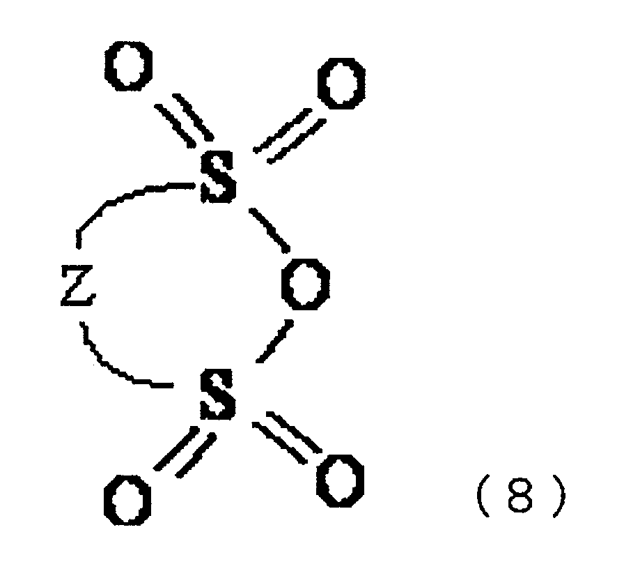
- Further, sultone compound represented by the following general formula (9) may be added:(where: n is an integer from 0 to 2; and R1 - R6 are separately selected from the group consisting of a hydrogen atom, an alkyl group containing 1 to 12 carbons, a cycloalkyl group containing 3 to 6 carbons and an aryl group containing 6 to 12 carbons.)

- In addition to cyclic sulfonic ester including at least two sulfonyl groups, the compound containing sulfonyl group represented by the general formula (8) and/or the general formula (9) may be added to suitably adjust the viscosity, thereby improving the stability of the coating, and to improve the prohibition of decomposition of solvent molecule and the removal of moisture.
- More specifically, the compounds containing sulfonyl group may be: sulfolane (JP-A-S60-154,478); 1,3-propane sultone or 1,4-propane sultone (JP-A-S62-100,948, JP-A-S63-102,173, JP-A-H11-339,850 and JP-A-2000-3,724); alkane sulfonate anhydride (JP-A-H10-189,041); γ-sultone compound (JP-A-2000-23,866); sulfolene derivatives (JP-A-2000-294,278) and so on, but not limited thereto.
- When a sulfonyl compound is added to the electrolyte solution in addition to cyclic sulfonic ester including at least two sulfonyl groups, the amount of addition of the sulfonyl compound may be adjusted to obtain a concentration thereof of 0.005 %wt. to 10 % wt. in the electrolyte solution. Having a concentration of not less than 0.005 % wt. provides effectively forming the coating on the anode. More preferably, the sulfonyl compound may be added at a concentration of not less than 0.01 % wt. On the other hand, a concentration of not higher than 10 % wt. provides maintaining good solubility of sulfonyl compound in the electrolyte solution, and prohibiting the increase of the viscosity of the electrolyte solution. More preferably, the sulfonyl compound may be added at a concentration of not higher than 5 % wt.
- When the compound represented by the above-shown general formula (8) or the compound represented by the above-shown general formula (9) is added into the
electrolyte solution 15, the compound may preferably be added at a weight ratio over the cyclic sulfonic ester including at least two sulfonyl groups of 0.01 to 100. This configuration ensures providing the combined effect of the plurality of additives. Thus, the cycle properties may further be improved. - The
electrolyte solution 15 may be obtained by dissolving or dispersing cyclic sulfonic ester including at least two sulfonyl groups, and optionally a compound containing a sulfonyl group, lithium salt and other additives as required, into a non-proton solvent. Additives having different properties are mixed to form coatings having different properties onto the anode, thereby improving the battery properties. - An imide anion and transition metal ion may additionally be added to the electrolyte solution as other additives. Alternatively, the electrolyte solution may include a lithium salt and metal complex of an imide anion and transition metal. More specifically, two methods are available for preparing this type of electrolyte solution: a method of dissolving an imide compound and transition metal compound and then dissolving the compound represented by general formula (1); and a method of dissolving the precedently synthesized metal complex of a transition metal cation and imide anion and then dissolving a cyclic sulfonic ester including at least two sulfonyl groups.
- When the
electrolyte solution 15 includes an imide anion and transition metal ion, a metal complex of an imide anion and transition metal is formed on the anode surface by conducting the charging and discharging (68th Annual Meeting of The Electrochemical Society of Japan (September 2000, at CHIBA INSTITUTE OF TECHNOLOGY, Number of presentation; 2A24), and The 41st Battery Symposium in Japan (November 2000, at NAGOYA INTERNATIONAL CONFERENCE HALL, Number of presentation; 1E03.)) Alternatively, when a metal complex of an imide anion and transition metal ion is included therein in advance, the aforementioned metal complex is adsorbed on the anode surface without conducting the charging and discharging, since the metal complex is already synthesized before being dissolved, thus there is no need to conduct the charging and discharging for carrying out synthesizing. Employing this type of metal complex containing an imide anion provides forming uniform coating on the anode surface in the electrolyte solution, so that the electrical field can be uniformly generated during the charging process, and thus a smooth absorption or deposition process of lithium can be achieved. In particular, when metallic lithium is employed, a coating that is chemically and physically resistant and has lower resistivity is formed on the anode. - In such case, two compounds of a metal complex of an imide anion and transition metal and a cyclic sulfonic ester including at least two sulfonyl groups simultaneously exist on the anode surface. A metal complex adsorbs onto the portions of the anode surface having no reactivity to function as a conductor of lithium ion, regardless of employing a metal complex generated by adding an imide salt or metal complex synthesized in advance from an imide salt and transition metal.
- A cyclic sulfonic ester including at least two sulfonyl groups is the critical component of the electrolyte solution for the secondary battery according to the present invention, and contributes in forming the passivating coating onto the anode surface, resulting in a decomposition of the solvent molecule being avoided. Further, a cyclic sulfonic ester including at least two sulfonyl groups reacts with a slight amount of water existing on the anode surface or in the electrolyte solution, and thus effectively removes moisture therefrom.
- Imide anions contained in the
electrolyte solution 15 may be, for example, a chemical species represented by -N(CnF2n+1SO2)(CmF2m+1SO2) (where n and m are independently integer of 1 to 6.) In particular, perfluoroethylsulfonylimideanion [-N(C2F5SO2)] is preferable in view of providing inhibition of aluminum corrosion. - A preferable transition metal may be a lanthanoid transition metal, and in particular, any one of europium (Eu), neodymium (Nd), erbium (Er) or holmium (Ho) or compounds thereof are more preferable. This is because the oxidation-reduction potentials of Eu, Nd, Er and Ho are equivalent to or higher than those of graphite, alloys and lithium, and because these metals are capable of being reduced at a potential of equivalent to or more than 0 V to 0.8 V higher than in the case of lithium. As such, the reduction of these metals can be prevented by selecting a metal to have an oxidation-reduction potential that is close to the oxidation-reduction potential of the anion active material, and selecting an anion that is capable of forming a stable complex with such metal. Thus, a complex of a lanthanoid transition metal and an imide anion is capable of more stably existing at the interface between the anode and the electrolyte solution.
- When the electrolyte solution is prepared by dissolving an imide compound and transition metal compound and then dissolving a cyclic sulfonic ester including at least two sulfonyl groups, an available imide compound and transition metal compound are not particularly limited, and the amount of addition of these compounds may preferably be adjusted to obtain a concentration thereof of 0.005 %wt. to 10 % wt. in the electrolyte solution. Having a concentration of not less than 0.005 % wt. provides propagating the advantageous effect of these compounds across the entire surface of the electrode, thereby providing a sufficient effect in forming the coating on the anode surface. More preferably, these compounds may be added at a concentration of not less than 0.05 % wt. On the other hand, a concentration of not higher than 10 % wt. provides prohibiting the increase of the viscosity of the electrolyte solution, and thus an increase of resistance of the electrolyte solution can be prevented. More preferably, the compound may be added at a concentration of not higher than 5 % wt. In such condition, the content of the sulfonic acid anhydride in the whole electrolyte solution may preferably be 0.01 %wt. to 10 % wt. Having a concentration of not less than 0.01 % wt. provides propagating the advantageous effect of these compounds across the entire surface of the electrode. Also, a concentration of not higher than 10 % wt. provides prohibiting an increase of the viscosity of the electrolyte solution, and thus the resistance of the electrolyte solution can be decreased.
- When the electrolyte solution is prepared by dissolving the precedently synthesized metal complex of a transition metal cation and imide anion and then dissolving a cyclic sulfonic ester including at least two sulfonyl groups, the available metal complex contained in the electrolyte solution is not particularly limited, and the concentration of the additional metal complex may preferably be 0.005 %wt. to 10 % wt. in the whole electrolyte solution for a similar reason as described above. In such condition, the content of sulfonic acid anhydride in the whole electrolyte solution may preferably be 0.01 %wt. to 10 % wt. for a similar reason as described above.
- The cycle properties and/or the effect of inhibiting the increase of resistance of the secondary battery can be improved by adding vinylene carbonate (VC) or derivatives thereof into the
electrolyte solution 15. Available VC or derivatives thereof are described in, for example, JP-A-H4-169,075, JP-A-H7-122,296, JP-A-H8-45,545, JP-A-H5-82,138, JP-A-H5-74,486, JP-A-H6-52,887, JP-A-H11-260,401, JP-A-2000-208,169, JP-A-2001-35,530 and JP-A-2000-138,071, and these disclosed compounds can be employed suitably. - The amount of addition of VC or derivatives thereof may preferably be adjusted to obtain a concentration thereof of 0.01 %wt. to 10 % wt. in the whole electrolyte solution. Having a concentration of not less than 0.01 % wt. provides obtaining preferable cycle properties, and further provides inhibiting an increase of resistance during storing at elevated temperature. Having a concentration of not higher than 10 % wt. provides decreasing the resistance of the electrolyte solution.
- The electrolyte solution for the secondary battery of this configuration may further have a constitution of additionally including lithium salt as an additional electrolyte. This constitution further improves the battery properties, since the lithium ion functions as a transportation material. The lithium salt may be one or more compound(s) selected from the group consisting of: lithium imide salt; LiPF6; LiBF4; LiAsF6; LiSbF6; LiClO4; LiAlCl4; and LiN(CnF2n+1SO2)(CmF2m+1SO2) (where: n and m are integer numbers.) In particular, LiPF6 or LiBF4 may preferably be employed. These compounds are used to enhance the electric conductivity of the lithium salt, thereby further improving the cycle properties of the secondary battery.
- The
electrolyte solution 15 may includes one or more solvent(s) as non-proton solvent selected from the group consisting of: cyclic carbonates; linear carbonates; aliphatic carboxylic acid esters; γ-lactones; cyclic ethers; linear ethers; and fluoro-derivatives thereof. - More specifically, the electrolyte solution may include one or mixture of two or more solvent(s) selected from the group consisting of: cyclic carbonates such as propylene carbonate (PC), ethylene carbonate (EC), butylene carbonate (BC), vinylene carbonate (VC) or the like; linear carbonates such as dimethyl carbonate (DMC), diethyl carbonate (DEC), ethylmethyl carbonate (EMC), dipropyl carbonate (DPC) or the like; aliphatic carboxylic acid esters such as methyl formate, methyl acetate, ethyl propionate or the like; γ-lactones such as γ-butyrolactone or the like; linear ethers such as 1,2-diethoxy ethane (DEE), ethoxymethoxy ethane (EME) or the like; cyclic ethers; such as tetrahydrofuran, 2-methyl tetrahydrofuran or the like; dimethyl sulfoxide; 1,3-dioxolane; formamide; acetamide; dimethyl formamide; acetonitrile; propylnitrile; nitromethane; ethylmonoglyme; phosphotriester; trimethoxymethane; dioxolane derivatives; sulfolane; methylsulfolane; 1,3-dimethyl-2- imidazolidinone; 3-methyl-oxazolidinone; propylenecarbonate derivatives; tetrahydrofuran derivatives; ethylether; N-methylpyrrolidone; fluorinated carboxylic acid ester; methyl-2,2,2-trifluoroethylcarbonate; methyl-2,2,3,3,3,-pentafluoropropylcarbonate; trifluoromethylethylenecarbonate; monofluoromethylethylenecarbonate; difluoromethylethylenecarbonate; 4,5-difluoro-1,3-dioxolane-2-one; and monofluoroethylenecarbonate.
- In the secondary battery shown in Fig. 1, the available anode active materials for use in the
layer 13 comprising the anode active material may be one or more selected from the group consisting of: for example, metallic lithium; lithium alloy; and materials capable of intercalating and deintercalating lithium. The available materials that are capable of intercalating and deintercalating lithium may be carbon materials or oxides. - The available carbon materials may be: graphite that is capable of absorbing lithium; amorphous carbons; diamond-like-carbons; carbon nanotube or the like; or combination of oxides thereof. In these materials, graphite materials and amorphous carbons are more preferable. In particular, graphite materials are particularly preferable, since graphite materials have higher electric conductivity, are superior in adhesiveness with the electric collector comprising metals such as copper, and electric voltage flatness, and contain less impurities because of being formed at elevated temperature, being advantageous in improving the anode characteristics.
- The available oxides may be one or a combination of: silicon oxide; tin oxide; indium oxide; zinc oxide; lithium oxide; phosphoric acid; or boric acid. In particular, the preferable oxide may contain silicon oxide. The state of the oxides may preferably be an amorphous state. These configurations are preferable because silicon oxide is stable so that there is very small concern in reacting with other materials, and because an amorphous state does not induce the deterioration of the quality due to the unevenness of the material such as forming crystal grain boundaries or defects. The preferable method for forming oxides may be vacuum evaporation, CVD (chemical vapor deposition), sputtering or the like.
- Lithium alloys may comprise lithium and a metal that is capable of forming alloys with lithium. For example, lithium alloys may be formed of a binary alloy or ternary alloy comprising lithium and, for example: Al; Si; Pb; Sn; In; Bi; Ag; Ba; Ca; Hg; Pd; Pt; Te; Zn; La or the like. The preferable metallic lithium or lithium alloy may be in an amorphous state. This is because an amorphous state does not induce the deterioration of the quality due to the unevenness of the material such as forming crystal grain boundaries or defects.
- The metallic lithium or lithium alloys may be produced by a suitable process such as: a melting and cooling process; liquid quenching process; atomization process; vacuum evaporation process; sputtering process; plasma CVD process; optical CVD process; thermal CVD process; sol-gel process or the like.
- In the anode of the secondary battery shown in Fig. 1, it is preferable to employ a complex of a transition metal cation and imide anion, which is located on the interface with the electrolyte solution, so that the anode is modified therewith to have flexibility or compliance against the volume variation of metal or alloy layers, to be uniform in ion distribution thereon and to be superior in physical and chemical stability. This modification of the anode may effectively prevent dendrite deposition and lithium pulverization, thereby improving the cycle properties and the life thereof.
- When carbon materials or oxide materials are employed for the anode, the dangling bond existing on the surface thereof, which has higher chemical activity, contributes to easily decompose the solvent. In order to solve this problem, a complex of a transition metal cation and imide anion is used to be adsorbed on the surface of the anode, so that the decomposition of the solvent is inhibited to considerably decrease the irreversible capacity, thereby maintaining the charging-discharging efficiency at higher level.
- Further, when the coating is mechanically damaged, lithium fluoride, which is a reaction product between lithium existing on the anode surface and the aforementioned imide anion adsorbing onto the anode surface, functions as repairing the damaged portion of the coating, and thus the configuration provides the advantageous effect of forming a stable surface compound even after the coating is damaged.
- In the present configuration, the available cathode active material may be lithium-containing combined oxides such as, for example, LiCoO2, LiNiO2, LiMn2O4 or the like, or substituted compounds of these lithium-containing combined oxides, the transition metal portion of which is substituted with other elements.
- Further, lithium-containing combined oxides having a plateau region at a metallic lithium counter electrode voltage of not less than 4.5 V may be employed. The available lithium-containing combined oxides may be: spinel structure lithium-manganese combined oxide; olivine structure lithium-containing combined oxide; inverse spinel structure lithium-containing combined oxide or the like. Lithium-containing combined oxide may be a compound represented by the general formula (10):
- The cathode of the secondary battery according to the present configuration may be produced by: dispersing and kneading these active materials into a solvent such as N-methyl-2- pyrrolidone (NMP) or the like with an electric conductive material such as carbon black or the like and a binder such as polyvinylidenefluoride (PVDF) or the like; and applying the obtained compound over a base material such as aluminum foil or the like.
- The secondary battery shown in Fig. 1 may be manufactured by: laminating an anode and a cathode with a separator therebetween in a dry air ambient or inert gas ambient; winding the lamination; then accommodating the resultant winded product within a battery can or encapsulating with a packaging such as a packaging made of a laminate of synthetic resin film and a metallic foil; and dipping the resultant winding product into the electrolyte solution represented by the above-shown general formula (1). Then, after the packaging is sealed, the secondary battery is charged, so that a coating is formed onto the anode surface. Here, the separator may be a porous film made of polyolefin such as polypropylene or polyethylene, or fluoro resin.
- The form of the secondary battery of the present invention is not particularly limited, but the secondary battery may be made in a form of cylinder shape, polygonal shape, laminated packaging shape, coin shape or the like.
- Preparation of the battery according to the present example will be described. An aluminum foil having a thickness of 20 µm was employed for a cathode active material, and LiMn2O4 was employed for an anode active material. A copper foil having a thickness of 10 µm was employed for an anode electric collector, and metallic lithium as an anode active material was deposited on the copper foil to a thickness of 20 µm to form an anode. A mixed solvent of EC and DEC (in a volumetric ratio of 30:70) was employed for an electrolyte solution, and 1 molL-1 of LiN(C2F5SO2)2 (hereinafter abbreviated to as LiBETI) as a support electrolyte was dissolved into the solvent, and further compound No. 1 shown in the above TABLE-1 was added thereto to achieve a concentration of compound No. 1 of 1 % wt. Then, the anode and the cathode were laminated, between which a separator comprising polyethylene was disposed, to form a laminate packaging secondary battery.
- Charge-discharge tests were conducted for the lithium secondary battery in a condition of: a temperature of 20°C, a charge rate of 0.05 C, a discharge rate of 0.1 C, a charge voltage of 4.2 V, a discharge terminated voltage of 3.0 V, and an occupancy rate of the metallic lithium anode (a discharge depth) of 30%. The capacity retention ratio (%) can be calculated by dividing a discharge capacity (mAh) after conducting 400 cycles by a discharge capacity (mAh) after conducting 10 cycles. The results obtained by conducting the cycle test are shown in TABLE-2.
- Secondary batteries were prepared in the same manner as in Example 1 except that compound No. 1 was replaced with the compound shown in TABLE-2. The battery properties were examined in the same manner as in Example 1. The results are shown in the TABLE-2.
- A secondary battery was prepared in the same manner as in Example 1 except that compound No. 1 was not added to the electrolyte solution. The battery properties were examined in the same manner as in Example 1. The results are shown in the TABLE-2.
- A secondary battery was prepared in the same manner as in Example 1 except that compound No. 1 is replaced with 1,3-propanesultone (1,3-PS.) The battery properties were examined in the same manner as in Example 1. The results are shown in the TABLE-2.
Anode Active Material Solvent Compound Represented by General Formula (1) Capacity Retention Ratio (%) after 400 cycles Example 1 Li metal EC/DEC Compound No. 1 86.7 Example 2 Li metal EC/DEC Compound No.4 83.1 Example 3 Li metal EC/DEC Compound No.9 82.9 Example 4 Li metal EC/DEC Compound No. 12 81.4 Comparative Example 1 Li metal EC/DEC none 45.6 Comparative Example 2 Li metal EC/DEC 1,3-PS 57.5 - It was confirmed that the batteries prepared in Examples 1-4 had improved capacity retention ratio after conducting the cycle tests, i.e., improved cycle properties, as compared with the batteries prepared in Comparative Examples 1 and 2.
- A secondary battery was prepared in the same manner as in Example 1 except that: LiBRTI for the support electrolyte was replaced with LiPF6; and the anode was prepared by applying onto a copper foil a paste mixture of graphite power, a binder of a mixture of a solvent of N-methyl-2- pyrrolidone and polyfluorovinylidene dissolved in the solvent and an electric conductor material, and drying the resultant copper foil. In this Example, a cylindrical secondary battery was prepared. The battery properties were examined in the same manner as in Example 1. The results are shown in the TABLE-3.
- Secondary batteries were prepared in the same manner as in Example 5 except that compound No. 1 was replaced with the compound shown in TABLE-3. The battery properties were examined in the same manner as in Example 5. The results are shown in the TABLE-3.
- A secondary battery was prepared in the same manner as in Example 5 except that compound No. 1 was not added to the electrolyte solution. The battery properties were examined in the same manner as in Example 5. The results are shown in the TABLE-3.
Anode Active Material Solvent Compound Represented by General Formula (1) Capacity Retention Ratio (%) after 400 cycles Example 5 graphite EC/DEC Compound No. 1 89.4 Example 6 graphite EC/DEC Compound No.4 85.2 Example 7 graphite EC/DEC Compound No.9 85.0 Example 8 graphite EC/DEC Compound No.12 83.9 Comparative Example 3 graphite EC/DEC none 78.5 - It was confirmed that the batteries prepared in Examples 5-8 had an improved capacity retention ratio after conducting the cycle tests, i.e., improved cycle properties, as compared with the battery prepared in Comparative Example 3.
- A secondary battery was prepared in the same manner as in Example 5 except that: graphite was replaced with amorphous carbon; and PC/EC/DEC (in a volumetric ratio of: 20/20/60) was employed for the main solvent of the electrolyte solution. The battery properties were examined in the same manner as in Example 5. The results are shown in the TABLE-4.
- Secondary batteries were prepared in the same manner as in Example 9 except that compound No. 1 was replaced with the compound shown in TABLE-4. The battery properties were examined in the same manner as in Example 9. The results are shown in the TABLE-3.
- A secondary battery was prepared in the same manner as in Example 9 except that compound No. 1 was not added to the electrolyte solution. The battery properties were examined in the same manner as in Example 9. The results are shown in the TABLE-4.
Anode Active Material Solvent Compound Represented by General Formula (1) Capacity Retention Ratio (%) after 400 cycles Example 9 amorphous carbon PC/EC/DEC Compound No.1 89.8 Example 10 amorphous carbon PC/EC/DEC Compound No.4 85.8 Example 11 amorphous carbon PC/EC/DEC Compound No.9 84.4 Example 12 amorphous carbon PC/EC/DEC Compound No. 12 82.5 Comparative Example 4 amorphous carbon PC/EC/DEC none 76.3 - It was confirmed that the batteries prepared in Examples 9-12 had improved an capacity retention ratio after conducting the cycle tests, i.e., improved cycle properties, as compared with the battery prepared in Comparative Example 4.
- A secondary battery was prepared in the same manner as in Example 1 except that the electrolyte solution further included 1,3-propanesultone (hereinafter abbreviated as 1,3-PS) at a concentration of 1 % wt. The battery properties were examined in the same manner as in Example 1. The results are shown in the TABLE-5.
- Secondary batteries were prepared in the same manner as in Example 13 except that compound No. 1 was replaced with the compound shown in TABLE-5. The battery properties were examined in the same manner as in Example 13. The results are shown in the TABLE-5.
Anode Active Material Solvent Compound Represented by General Formula (1) Other Additives Capacity Retention Ratio (%) after 400 cycles Example 13 Li metal EC/DEC Compound No.1 1,3-PS 90.9 Example 14 Li metal EC/DEC Compound No.4 1,3-PS 87.5 Example 15 Li metal EC/DEC Compound No.9 1,3-PS 87.2 Example 16 Li metal EC/DEC Compound No.12 1,3-PS 85.8 Comparative Example 1 Li metal EC/DEC none none 45.6 - It was confirmed that the batteries prepared in Examples 13-16 had an improved capacity retention ratio after conducting the cycle tests, i.e., improved cycle properties, as compared with the batteries prepared in Examples 1-4 and Comparative Example 1. This is due to the combined advantageous effects raised by the use of the compound represented by the general formula (1) and by the use of 1,3-PS.
- A secondary battery was prepared in the same manner as in Example 5 except that the electrolyte solution further included 1,3-propanesultone (hereinafter abbreviated as 1,3-PS) at a concentration of 1 % wt. The battery properties were examined in the same manner as in Example 5. The results are shown in the TABLE-6.
- Secondary batteries were prepared in the same manner as in Example 17 except that compound No. 1 was replaced with the compound shown in TABLE-6. The battery properties were examined in the same manner as in Example 17. The results are shown in the TABLE-6.
Anode Active Material Solvent Compound Represented by General Formula (1) Other Additives Capacity Retention Ratio (%) after 400 cycles Example 17 graphite EC/DEC Compound No.1 1,3-PS 90.6 Example 18 graphite EC/DEC Compound No.4 1,3-PS 87.5 Example 19 graphite EC/DEC Compound No.9 1,3-PS 86.9 Example 20 graphite EC/DEC Compound No.12 1,3-PS 85.9 Comparative Example 3 graphite EC/DEC none none 78.5 - It was confirmed that the batteries prepared in Examples 17 to 20 had an improved capacity retention ratio after conducting the cycle tests, i.e., improved cycle properties, as compared with the batteries prepared in Examples 5 to 8 and Comparative Example 3. This is due to the combined advantageous effects raised by the use of the compound represented by the general formula (1) and by the use of 1,3-PS.
- A secondary battery was prepared in the same manner as in Example 9 except that the electrolyte solution further included 1,3-propanesultone (hereinafter abbreviated as 1,3-PS) at a concentration of 1 % wt. The battery properties were examined in the same manner as in Example 9. The results are shown in the TABLE-7.
- Secondary batteries were prepared in the same manner as in Example 21 except that compound No. 1 was replaced with the compound shown in TABLE-7. The battery properties were examined in the same manner as in Example 21. The results are shown in the TABLE-7.
Anode Active Material Solvent Compound Represented by General Formula (1) Other Additives Capacity Retention Ratio (%) after 400 cycles Example 21 amorphous carbon PC/EC/DEC Compound No.1 1,3-PS 90.7 Example 22 amorphous carbon PC/EC/DEC Compound No.4 1,3-PS 87.8 Example 23 amorphous carbon PC/EC/DEC Compound No.9 1,3-PS 86.8 Example 24 amorphous carbon PC/EC/DEC Compound No.12 1,3-PS 84.6 Comparative Example 4 amorphous carbon PC/EC/DEC none none 76.3 - It was confirmed that the batteries prepared in Examples 21-24 had an improved capacity retention ratio after conducting the cycle tests, i.e., improved cycle properties, as compared with the batteries prepared in Examples 9-12 and Comparative Example 4. This is due to the combined advantageous effects raised by the use of the compound represented by the general formula (1) and by the use of 1,3-PS.
- Secondary batteries were prepared in the same manner as in Example 9 except that the electrolyte solution further included salts of lanthanide transition metals shown in TABLE-8 having a CF3SO3 - anion at a concentration of 0.3 % wt. The battery properties were examined in the same manner as in Example 9. The results are shown in the TABLE-8.
Anode Active Material Solvent Transition Metal Ion Compound Represented by General Formula (1) Capacity Retention Ratio (%) after 400 cycles Example 25 amorphous carbon PC/EC/DEC Eu3+ Compound No. 1 91.2 Example 26 amorphous carbon PC/EC/DEC Ho3+ Compound No.1 90.3 Example 27 amorphous carbon PC/EC/DEC Nd3+ Compound No. 1 89.6 Example 28 amorphous carbon PC/EC/DEC Er3+ Compound No.1 89.4 Comparative Example 4 amorphous carbon PC/EC/DEC none none 76.3 - It was confirmed that the batteries prepared in Examples 25-28 had an improved capacity retention ratio after conducting the cycle tests, i.e., improved cycle properties, as compared with the batteries prepared in Comparative Example 4 and Example 9.
- Secondary batteries were prepared in the same manner as in Example 9 except that the electrolyte solution further included lanthanide transition metal complex listed in TABLE-9 at a concentration of 0.1 % wt. The battery properties were examined in the same manner as in Example 9. The results are shown in the TABLE-9.
Anode Active Material Solvent Metal Complex Compound Represented by General Formula (1) Capacity Retention Ratio (%) after 400 cycles Example 29 amorphous carbon PC/EC/DEC Eu[N(C2F5SO2)2]3 Compound No.1 91.8 Example 30 amorphous carbon PC/EC/DEC Ho[N(C2F5SO2)2]3 Compound No.1 90.9 Example 31 amorphous carbon PC/EC/DEC Nd[N(C2F5SO2)2]3 Compound No.1 90.6 Example 32 amorphous carbon PC/EC/DEC Er[N(C2F5SO2)2]3 Compound No.1 90.1 Comparative Example 4 amorphous carbon PC/EC/DEC none none 76.3 - It was confirmed that the batteries prepared in Examples 29-32 had improved cycle properties as compared with the batteries prepared in Comparative Example 4 and Example 9.
- A secondary battery was prepared in the same manner as in Example 9 except that the electrolyte solution further included vinylene carbonate (hereinafter abbreviated as VC) at a concentration of 1 % wt. The battery properties were examined in the same manner as in Example 9. The results are shown in the TABLE-10.
- Secondary batteries were prepared in the same manner as in Example 33 except that compound No. 1 was replaced with the compound shown in TABLE-10. The battery properties were examined in the same manner as in Example 33. The results are shown in the TABLE-10.
Anode Active Material Solvent Compound Represented by General Formula (1) Other Additives Capacity Retention Ratio (%) after 400 cycles Example 33 amorphous carbon PC/EC/DEC Compound No.1 VC 90.6 Example 34 amorphous carbon PC/EC/DEC Compound No.4 VC 88.5 Example 35 amorphous carbon PC/EC/DEC Compound No.9 VC 88.3 Example 36 amorphous carbon PC/EC/DEC Compound No.12 VC 86.2 Comparative Example 4 amorphous carbon PC/EC/DEC none none 76.3 - It was confirmed that the batteries prepared in Examples 33-36 had an improved capacity retention ratio after conducting the cycle tests, i.e., improved cycle properties, as compared with the batteries prepared in Comparative Example 4 and Examples 9-12.
- A secondary battery was prepared in the same manner as in Example 9 except that the electrolyte solution further included vinylene carbonate (hereinafter abbreviated as VC) and 1,3-PS at respective concentration of 1 % wt. The battery properties were examined in the same manner as in Example 9. The results are shown in the TABLE-11.
- Secondary batteries were prepared in the same manner as in Example 37 except that compound No. 1 was replaced with the compound shown in TABLE-11. The battery properties were examined in the same manner as in Example 37. The results are shown in the TABLE-11.
Anode Active Material Solvent Compound Represented by General Formula (1) Other Additives Capacity Retention Ratio (%) after 400 cycles Example 37 amorphous carbon PC/EC/DEC Compound No.1 VC+1,3-PS 91.9 Example 38 amorphous carbon PC/EC/DEC Compound No.4 VC+1,3-PS 89.9 Example 39 amorphous carbon PC/EC/DEC Compound No.9 VC+1,3-PS 88.7 Example 40 amorphous carbon PC/EC/DEC Compound No.12 VC+1,3-PS 87.2 Comparative Example 4 amorphous carbon PC/EC/DEC none none 76.3 - It was confirmed that the batteries prepared in Examples 38-40 had an improved capacity retention ratio after conducting the cycle tests, i.e., improved cycle properties, as compared with the batteries prepared in Comparative Example 4 and Examples 9-12 and Examples 33-36. This is due to the combined advantageous effects raised by the use of the compound represented by the general formula (1) and by the use of VC and 1,3-PS.
- A secondary battery was prepared in the same manner as the one prepared in Example 9, using compound No. 1 as one additive for the electrolyte solution. In this example, resistance variation of the secondary battery during storage was measured. First, one charging operation and one discharging operation of the prepared secondary battery were conducted at 20°C. The charging current and discharging current of these charging and discharging processes were constant, and the discharging capacity at this discharging process was determined as an initial capacity and the resistance of this occasion was determined as an initial resistance. Then, discharging operation was carried out at constant current and voltage to achieve a predetermined voltage for 2.5 hours, and after that the secondary battery was left for 90 days in a condition of 45°C and 60°C. After that, discharging operation under the constant current was carried out again at 20°C, and subsequently one charging operation and one discharging operation of the prepared secondary battery were conducted again similarly at a constant current at 20°C, and the resistance and capacity during the discharging operation were measured. The results of the resistance after 90day-storage (45°C-storage or 60°C-storage) are shown in TABLE-12, in relative values converted by the initial resistance as the initial resistance value is taken as 1. Also, the results of the capacity retention rate after conducting 60°C-storage ([discharging capacity]/[initial discharging capacity] after 90 days) are shown in TABLE-12.
- Secondary batteries were prepared in the same manner as the one prepared in Example 9, using the compounds shown in TABLE-12 as additives for the electrolyte solutions, and the evaluations were conducted in the same manner as in Example 41. The results are shown in the TABLE-12.
- A secondary battery was prepared in the same manner as in Example 41 except that 1,3-PS was employed as an additive for the electrolyte solution, and the evaluations were conducted in the same manner as in Example 41. The results are shown in the TABLE-12.
Compound Represented by General Formula (1) Resistance Increase Rate after 90 days (45 Deg. C Storage) Resistance Increase Rate after 90 days (60 Deg. C Storage) Capacity Retention Ratio after 90 days (60 Deg. C Storage) Example 41 Compound No. 1 1.05 1.18 0.84 Example 42 Compound No.4 1.08 1.21 0.83 Example 43 Compound No.9 1.09 1.23 0.83 Example 44 Compound No.12 1.09 1.24 0.82 Example 45 Compound No.2 1.10 1.26 0.82 Example 46 Compound No.17 1.10 1.25 0.82 Example 47 Compound No. 18 1.11 1.26 0.81 Comparative Example 5 1,3-PS 1.45 1.61 0.75 - As can be seen in TABLE-12, it is recognized that each of the batteries prepared in Examples 41-47 had smaller resistance increase rates at a respective temperature, as compared with the battery prepared in Comparative Example 5 which includes the conventional 1,3-PS, and thus it is proved that the prohibitions of the increase of resistance were successfully achieved in these examples. In particular, the considerable advantage in prohibiting the increase of resistance under 60°C was achieved. Further, the capacity retention rates were considerably improved as compared with Comparative Example 5.
- A secondary battery was prepared in the same manner as the one prepared in Example 33, using compound No. 1 as one additive for the electrolyte solution, and the evaluation was conducted in the same manner as in Example 41. The results are shown in the TABLE-13.
- Secondary batteries were prepared in the same manner as the one prepared in Example 33, using the compounds shown in TABLE-13 as additives, and the evaluations were conducted in the same manner as in Example 48. The results are shown in the TABLE-13.
- A secondary battery was prepared in the same manner as in Example 48 except that 1,3-PS was employed as an additive for the electrolyte solution, and the evaluations were conducted. The results are shown in the TABLE-13.
Compound Represented by General Formula (1) Resistance Increase Rate after 90 days
(45 Deg. C Storage)Resistance Increase Rate after 90 days
(60 Deg. C Storage)Capacity Retention Ratio after 90 days
(60 Deg. C Storage)Example 48 Compound No.1 1.01 1.14 0.88 Example 49 Compound No.4 1.05 1.19 0.86 Example 50 Compound No.9 1.03 1.18 0.86 Example 51 Compound No.12 1.05 1.20 0.86 Example 52 Compound No.2 1.02 1.17 0.85 Example 53 Compound No.17 1.03 1.20 0.84 Example 54 Compound No.18 1.05 1.22 0.84 Comparative Example 6 1,3-PS 1.21 1.55 0.76 - As can be seen in TABLE-13, it is proved that prohibition of the increase of resistance was successfully achieved in these examples, as compared with the battery prepared in Comparative Example 6 which includes the conventional 1,3-PS. In particular, the considerable advantage of prohibiting the increase of resistance under 60°C was achieved. Further, the capacity retention rates were considerably improved as compared with Comparative Example 5.
- In this example, a combined oxide of lithium manganate and lithium nickelate was employed for the cathode. A film packaging battery was experimentally prepared by using LiNi0.8Co0.2O2 having a specific surface area of 1.7 m2/g and a packaging material of aluminum laminate film.
- First, lithium manganate, LiNi0.8Co0.2O2 and an electric conductivity-providing agent were mixed in a dry condition, and the resultant mixture was uniformly dispersed into N-methyl-2- pyrrolidone (NMP) containing PVDF dissolved therein as a binder to obtain a slurry. Carbon black was employed for the electric conductivity-providing agent. The slurry was applied onto an aluminum metal foil having a thickness of 25 µm, and NMP contained in the slurry was evaporated to form a cathode sheet. The solid contents contained in the cathode was set to a ratio of: lithium manganate: LiNi0.8Co0.2O2: an electric conductivity-providing agent: PVDF = 72:8:10:10.
- At the same time, the anode sheet was prepared by mixing carbon and PVDF at a volumetric ratio of carbon:PDVF = 90:10 (% vol.), dispersing the resultant mixture into NMP, applying the slurry onto a copper foil of 20 µm thick and evaporating the solvent to obtain the anode sheet.
- The plurality of resultant electrode sheets for the cathode and the anode were alternately built-up, with a polyethylene porous film separator having a thickness of 25 µm being interposed between each anode sheet and each cathode sheet, to form a laminate electrode member having 12 layers of cathode and 13 layers of anode.
- At the same time, a laminate film having a construction comprising polypropylene resin (sealed, thickness: 70 µm), polyethylene terephthalate (20 µm), aluminum (50 µm), and polyethylene terephthalate (20 µm) built-up in this turn was cut into two sheets having predetermined sizes, and a recess comprising a bottom portion and side portions having a dimension being conformal to the dimension of the above-mentioned laminate electrode member on the sheets. These two sheets having recesses were oppositely superimposed so that each recess of each sheet faced to house the above-mentioned laminate electrode member, and then the outer peripheries of the sheets were thermally fused and bonded to form the film packaging battery. Before the last periphery thereof was bonded, the electrolyte solution was introduced therein for dipping the laminate electrode member into the electrolyte solution.
- The electrolyte solution employed in this example included 0.9 M of LiPF6 as a support salt. The solvent for the electrolyte solution was a mixed solvent of propylene carbonate (PC), ethylene carbonate (EC) and diethyl carbonate (DEC) (volumetric ratio: 20:20:60 (% vol.)). Additionally, compound No. 1 was dissolved into the solution at a concentration of the compound in the electrolyte solution of 0.1 M, to obtain the electrolyte solution of the present example.
- The laminate packaging secondary battery (120 mm x 80 mm x 4 mm) of Example 55 was prepared as described above. Charging and discharging operations were conducted by using the laminate packaging secondary battery at 25°C by the following procedure: charging operation was conducted in a condition of a constant current of 0.4 A and a constant voltage for 12.5 hours to achieve a final voltage of 4.3 V; and discharging operation was conducted at a constant current of 2 A so to achieve a final voltage of 2.5 V; and then charging operation was conducted again in a condition of a constant current of 2 A and a constant voltage for 2.5 hours to achieve a final voltage of 4.3 V.
- The storage properties were evaluated by using the thus obtained secondary battery. First, one charging operation and one discharging operation were carried out at 25°C. The charging current and the discharging current in these operations were constant (2A), and the discharging capacity at this discharging process was determined as an initial capacity and the resistance of this occasion was determined as an initial resistance. Here, the cutoff potential at the discharging side was set to 2.5 V, and the cutoff potential at the charging side was set to 4.2 V. Then, charging and discharging operations were conducted by the following procedure: charging operation was conducted in a condition of a constant current of 2 A and a constant voltage for 2.5 hours to achieve 4.2 V; and then after the discharging operation was conducted to achieve 50 % in the discharging depth, the secondary batteries were left or stored at 55°C for 7 days, 28 days, 56 days and 84 days. After the storage, the discharging operation was conducted again at a constant current at 25°C, and subsequently, the charging was conducted at a constant current and constant voltage, and then discharging was carried out at a constant current, and in this occasion, the discharging capacity was taken as a recovery capacity. Further, the charging was conducted at a constant current and constant voltage, and then after the discharging operation was conducted to achieve 50 % in the discharging depth, charging-discharging operations were repeated for 10 seconds at 2A, 6A and 14A, so that the resistances were obtained by the correlation of the current and the voltage. The number of the experiences was 3.
- As shown in Fig. 2, the capacity recovery rate or the rate of the recovery of the capacity over the square root of the days for storing was significantly improved, as compared with the after-mentioned Comparative Example 7 utilizing an electrolyte solution without any additives and the Comparative Example 8 utilizing an electrolyte solution with 1,3-PS (0.1 M) and VC (0.1M). Further, as shown in Fig. 3, the resistance increase rate over the square root of the days for storing was significantly prohibited, as compared with the after-mentioned Comparative Example 7 utilizing an electrolyte solution without any additives and the after-mentioned Comparative Example 8 utilizing a electrolyte solution with 1,3-PS (0.1 M) and VC (0.1M).
- It is considered that these results are obtained because the compounds represented by the general formula (1) of the present invention, which are added to the electrolyte solution, provide higher ion conductivity as compared with non-additive type electrolyte solution or conventional type electrolyte solution, and thus coating films with higher stability during the storage are formed. Fig. 4 shows the volume variation of the laminate packaging cell over the square root of days of storing. The volumetric variation of the cell in Example 55 is small, as compared with Comparative Examples 7 and 8. It is considered that this is because the coating generated by the decomposition of the compound represented by the general formula (1) is formed on the anode, so that decomposition of the electrolyte solution or the gas emission due to the decomposition of the electrolyte solution is prohibited.
- A laminate packaging secondary battery was prepared in the same manner as in Example 55 except that: the electrolyte solution included 0.9 M of LiPF6 as a support salt; the solvent for the electrolyte solution was a mixed solvent of propylene carbonate (PC), ethylene carbonate (EC) and diethyl carbonate (DEC) (volumetric ratio: 20:20:60 (% vol.)); and additionally compound No. 1 and 1,3-PS were dissolved into the solution at a concentration of the compound in the electrolyte solution of 0.1 M, respectively. The number of the experiences was 3.
- As shown in Fig. 2, the capacity recovery rate or the rate of the recovery of the capacity over the square root of the days for storing was significantly improved, as compared with the after-mentioned Comparative Example 7 utilizing an electrolyte solution without any additives and the after-mentioned Comparative Example 8 utilizing an electrolyte solution with 1,3-PS (0.1 M) and VC (0.1M). Further, as shown in Fig. 3, the resistance increase rate over the square root of the days for storing was significantly prohibited, as compared with the after-mentioned Comparative Example 7 utilizing an electrolyte solution without any additives and the after-mentioned Comparative Example 8 utilizing an electrolyte solution with 1,3-PS (0.1 M) and VC (0.1M).
- It is considered that these results are obtained because the compounds represented by the general formula (1) of the present invention and 1,3-PS, both of which are added to the electrolyte solution, provide higher ion conductivity as compared with non-additive type electrolyte solution or conventional type electrolyte solution, and thus coating films with higher stability during the storage are formed.
- Also, Fig. 4 shows the volume variation of the laminate packaging cell over the square root of days of storing. The volumetric variation of the cell in Example 56 is small, as compared with Comparative Examples 7 and 8 and Example 55. It is considered that this is because the coating generated due to the combined effect of the compound represented by the general formula (1) and 1,3-PS is formed on the anode, so that the decomposition of the electrolyte solution or the gas emission due to decomposition of the electrolyte solution is prohibited.
- A laminate packaging secondary battery was prepared in the same manner as in Example 55 and evaluation thereof was conducted except that: the electrolyte solution included 0.9 M of LiPF6 as a support salt; the solvent for the electrolyte solution was a mixed solvent of propylene carbonate (PC), ethylene carbonate (EC) and diethyl carbonate (DEC) (volumetric ratio: 20:20:60 (% vol.)); and no additive was added therein. The number of the experiences was 3. The results are shown in Figs. 2-4.
- A laminate packaging secondary battery was prepared in the same manner as in Example 55 and evaluation thereof was conducted except that: the electrolyte solution included 0.9 M of LiPF6 as a support salt; the solvent for the electrolyte solution was a mixed solvent of propylene carbonate (PC), ethylene carbonate (EC) and diethyl carbonate (DEC) (volumetric ratio: 20:20:60 (% vol.)); and additionally 1,3-PS and VC were dissolved into the solution at a concentration of the compound in the electrolyte solution of 0.1 M, respectively. The number of the experiences was 3. The results are shown in Figs. 2-4.
- Secondary batteries were prepared in the same manner as in Example 9 except that compound No. 1 was replaced with compound No. 21 shown in TABLE-1. The battery properties were examined in the same manner as in Example 9. The capacity retention ratio after 400 cycles was 80.1 %. It was confirmed that the battery prepared in Example 57 had improved capacity retention ratio after conducting the cycle tests, i.e., improved cycle properties, as compared with the battery prepared in Comparative Example 4.
- Secondary batteries were prepared in the same manner as in Example 9 except that compound No. 1 was replaced with compound No. 22 shown in TABLE-1. The battery properties were examined in the same manner as in Example 9. The capacity retention ratio after 400 cycles was 83.4 %. It was confirmed that the battery prepared in Example 57 had improved capacity retention ratio after conducting the cycle tests, i.e., improved cycle properties, as compared with the battery prepared in Comparative Example 4.
- As described above, the efficiency of charging and discharging of the secondary battery is improved by producing the secondary battery employing the electrolyte solution comprising non-proton solvent and cyclic sulfonic ester including at least two sulfonyl groups. Also, the present invention provides improvement in the cycle properties of the secondary battery. In addition, the present invention provides prohibition of the increase of the resistance during storage. Further, since the present invention can be applied in a secondary battery comprising a laminate film packaging so that the increase of the resistance, the blistering of the battery itself and the emission of gases can be prohibited, the secondary battery according to the present invention is suitably applicable in the lithium ion secondary battery for larger sized applications such as automotive applications.
Claims (29)
- An electrolyte solution for a secondary battery, comprising a non-proton solvent and a cyclic sulfonic ester including at least two sulfonyl groups.
- The electrolyte solution for a secondary battery according to claim 1, wherein said cyclic sulfonic ester is a compound represented by general formula (1) described below:(where: Q is an oxygen atom, a methylene group or a single bond; A is a substituted or non-substituted alkylene group containing 1 to 5 carbons, a carbonyl group, a sulfinyl group, a substituted or non-substituted fluoroalkylene group containing 1 to 6 carbons or a divalent group containing 2 to 6 carbons being bonded to an alkylene unit or a fluoroalkylene unit via an ether bond; and B is a substituted or non-substituted alkylene group, a substituted or non-substituted fluoroalkylene group or an oxygen atom.)

- The electrolyte solution for a secondary battery according to claim 2, wherein said compound represented by general formula (1) is a cyclic disulfonic ester represented by the following general formula (2):(where: x is 0 or 1; n is an integer from 1 to 5; and R is a hydrogen atom, a methyl group, an ethyl group or a halogen atom).

- The electrolyte solution for a secondary battery according to claim 2, wherein said compound represented by general formula (1) is a cyclic disulfonic ester represented by the following general formula (3):(where: x is 0 or 1; n is an integer from 1 to 5; and R is a hydrogen atom, a methyl group, an ethyl group or a halogen atom).

- The electrolyte solution for a secondary battery according to claim 2, wherein said compound represented by general formula (1) is a cyclic disulfonic ester represented by the following general formula (4):(where: x is 0 or 1; m is 1 or 2; n is an integer from 1 to 4; and R is a hydrogen atom, a methyl group, an ethyl group or a halogen atom).

- The electrolyte solution for a secondary battery according to claim 2, wherein said compound represented by general formula (1) is a cyclic disulfonic ester represented by the following general formula (5):(where: x is 0 or 1; m is 1 or 2; n is an integer from 1 to 4; and R is a hydrogen atom, a methyl group, an ethyl group or a halogen atom).

- The electrolyte solution for a secondary battery according to claim 2, wherein said compound represented by general formula (1) is a cyclic disulfonic ester represented by the following general formula (6):(where: x is 0 or 1; m is 1 or 2; n is an integer from 1 to 4; and R is a hydrogen atom, a methyl group, an ethyl group or a halogen atom).

- The electrolyte solution for a secondary battery according to claim 2, wherein said compound represented by general formula (1) is a cyclic disulfonic ester represented by the following general formula (7):(where: x is 0 or 1; m is 1 or 2; n is an integer from 1 to 4; and R is a hydrogen atom, a methyl group, an ethyl group or a halogen atom).

- The electrolyte solution for a secondary battery according to claim 1, further comprising a compound having at least one sulfonyl group, in addition to said cyclic sulfonic ester.
- The electrolyte solution for a secondary battery according to claim 9, wherein said compound having at least one sulfonyl group is included at a weight ratio over said cyclic sulfonic ester of 0.01 to 100.
- The electrolyte solution for a secondary battery according to claim 9, wherein said compound having at least one sulfonyl group is a compound represented by the following general formula (8):(where: Z is a substituted or non-substituted alkylene group containing 2 to 4 carbons, a substituted or non-substituted alkenylene group containing 2 to 4 carbons, a substituted or non-substituted aromatic cyclic group or a substituted or non-substituted hetero cyclic group.)

- The electrolyte solution for a secondary battery according to claim 9, wherein said compound having at least one sulfonyl group is a sultone compound represented by the following general formula (9):(where: n is an integer from 0 to 2; and R1 to R6 are separately selected from the group consisting of a hydrogen atom, alkyl group containing 1 to 12 carbons, a cycloalkyl group containing 3 to 6 carbons and an aryl group containing 6 to 12 carbons.)

- The electrolyte solution for a secondary battery according to claim 1, further comprising an imide anion and a transition metal ion.
- The electrolyte solution for a secondary battery according to claim 1, further comprising a metal complex of an imide anion and a transition metal ion.
- The electrolyte solution for a secondary battery according to claim 13, wherein said transition metal ion is a lanthanoid transition metal ion.
- The electrolyte solution for a secondary battery according to claim 15, wherein said lanthanoid transition metal ion is selected from the group consisting of: europium ion; neodymium ion; erbium ion; and holmium ion.
- The electrolyte solution for a secondary battery according to claim 13, wherein said imide anion is represented by -N(CnF2n+1SO2)(CmF2m+1SO2) (where each of n and m is independently an integer of 1 to 6.)
- The electrolyte solution for a secondary battery according to claim 13, wherein said imide anion or metal complex thereof is included in said electrolyte solution at a concentration of 0.005 % wt. to 10 % wt.
- The electrolyte solution for a secondary battery according to claim 1, wherein said cyclic sulfonic ester is included in said electrolyte solution at a concentration of 0.005 % wt. to 10 % wt.
- The electrolyte solution for a secondary battery according to claim 1, further comprising vinylene carbonate or derivatives thereof.
- The electrolyte solution for a secondary battery according to claim 1, wherein said non-proton solvent includes one or more solvent(s) selected from the group consisting of: cyclic carbonates; linear carbonates; aliphatic carboxylic acid esters; γ-lactones; cyclic ethers; linear ethers; and fluoro-derivatives thereof.
- The electrolyte solution for a secondary battery according to claim 1, further comprising lithium salt(s), which is/are one or more compound(s) selected from the group consisting of: LiPF6; LiBF4; LiAsF6; LiSbF6; LiClO4; LiAlCl4; and LiN(CnF2n+1SO2)(CmF2m+1SO2) (where: n and m are integer numbers.)
- A secondary battery comprising at least a cathode and an anode, said secondary battery including the electrolyte solution according to any one of claims 1 to 22.
- The secondary battery according to claim 23, further comprising a cathode active material of a lithium-containing combined oxide.
- The secondary battery according to claim 23, further comprising an anode active material of one or more material(s) selected from the group consisting of: a material being capable of intercalating and deintercalating lithium; a metallic lithium; a lithium alloy; and a metal material being capable of forming an alloy with lithium.
- The secondary battery according to claim 25, wherein said anode active material contains a carbon material.
- The secondary battery according to claim 26, wherein said carbon material is graphite.
- The secondary battery according to claim 26, wherein said carbon material is amorphous carbon.
- The secondary battery according to claim 23, further comprising a film packaging.
Applications Claiming Priority (6)
| Application Number | Priority Date | Filing Date | Title |
|---|---|---|---|
| JP2002250441 | 2002-08-29 | ||
| JP2002250441 | 2002-08-29 | ||
| JP2003052588 | 2003-02-28 | ||
| JP2003052588 | 2003-02-28 | ||
| JP2003289432A JP4033074B2 (en) | 2002-08-29 | 2003-08-07 | Secondary battery electrolyte and secondary battery using the same |
| JP2003289432 | 2003-08-07 |
Publications (2)
| Publication Number | Publication Date |
|---|---|
| EP1394888A1 true EP1394888A1 (en) | 2004-03-03 |
| EP1394888B1 EP1394888B1 (en) | 2006-04-12 |
Family
ID=31499128
Family Applications (1)
| Application Number | Title | Priority Date | Filing Date |
|---|---|---|---|
| EP03090268A Expired - Lifetime EP1394888B1 (en) | 2002-08-29 | 2003-08-22 | Electrolyte solution for secondary battery and secondary battery using the same |
Country Status (6)
| Country | Link |
|---|---|
| US (1) | US7163768B2 (en) |
| EP (1) | EP1394888B1 (en) |
| JP (1) | JP4033074B2 (en) |
| KR (1) | KR100538901B1 (en) |
| CN (1) | CN1280942C (en) |
| DE (1) | DE60304522T2 (en) |
Cited By (15)
| Publication number | Priority date | Publication date | Assignee | Title |
|---|---|---|---|---|
| WO2006030681A1 (en) | 2004-09-17 | 2006-03-23 | Sanyo Electric Co., Ltd. | Non-aqueous electrolyte secondary battery and non-aqueous electrolyte |
| EP2031689A1 (en) * | 2006-06-02 | 2009-03-04 | Mitsubishi Chemical Corporation | Nonaqueous electrolyte solution and nonaqueous electrolyte battery |
| EP2109177A1 (en) * | 2008-04-07 | 2009-10-14 | NEC TOKIN Corporation | Non-aqueous electrolyte and non-aqueous electrolyte secondary battery using the same |
| EP2503632A1 (en) * | 2011-03-23 | 2012-09-26 | Sony Corporation | Secondary battery, as well as electronic device, electric power tool, electrical vehicle, and electric power storage system using said secondary battery |
| EP2503634A1 (en) * | 2009-11-19 | 2012-09-26 | NEC Energy Devices, Ltd. | Method for manufacturing lithium ion secondary battery |
| EP2535974A1 (en) * | 2010-02-08 | 2012-12-19 | NEC Energy Devices, Ltd. | Nonaqueous electrolyte secondary battery |
| EP2597717A1 (en) * | 2007-04-05 | 2013-05-29 | Mitsubishi Chemical Corporation | Nonaqueous electrolyte for secondary battery and nonaqueous-electrolyte secondary battery employing the same |
| EP2744030A1 (en) * | 2011-08-12 | 2014-06-18 | UBE Industries, Ltd. | Non-aqueous electrolyte and electricity storage device using same |
| EP2916374A4 (en) * | 2012-10-30 | 2016-05-18 | Nec Corp | Lithium secondary cell |
| EP3113247A1 (en) * | 2015-06-30 | 2017-01-04 | Automotive Energy Supply Corporation | Lithium ion secondary battery |
| US9711825B2 (en) | 2013-03-01 | 2017-07-18 | Nec Corporation | Lithium ion secondary battery |
| US9941545B2 (en) | 2013-03-01 | 2018-04-10 | Nec Corporation | Electrolyte solution for secondary batteries, and secondary battery using same |
| US10069166B2 (en) | 2013-12-26 | 2018-09-04 | Nec Corporation | Cyclic sulfonic acid ester compound, non-aqueous electrolyte solution, and lithium ion secondary battery using same |
| EP3664212A4 (en) * | 2017-07-31 | 2020-09-16 | Shenzhen Capchem Technology Co., Ltd | Lithium ion battery non-aqueous electrolyte and lithium ion battery |
| EP3618163A4 (en) * | 2017-04-28 | 2021-01-27 | Zhangjiagang Guotai-Huarong New Chemical Materials Co., Ltd | Non-aqueous electrolyte solution, and secondary battery |
Families Citing this family (90)
| Publication number | Priority date | Publication date | Assignee | Title |
|---|---|---|---|---|
| JP4618399B2 (en) * | 2002-06-11 | 2011-01-26 | 日本電気株式会社 | Secondary battery electrolyte and secondary battery using the same |
| US7608364B2 (en) * | 2003-01-10 | 2009-10-27 | Nec Corporation | Lithium ion secondary battery |
| JP4315705B2 (en) * | 2003-02-27 | 2009-08-19 | 三洋電機株式会社 | Non-aqueous lithium secondary battery |
| JP4444572B2 (en) * | 2003-02-28 | 2010-03-31 | Tdk株式会社 | Electrode manufacturing method and battery manufacturing method |
| WO2005029613A1 (en) * | 2003-09-16 | 2005-03-31 | Nec Corporation | Nonaqueous electrolyte secondary battery |
| US8227116B2 (en) * | 2003-12-15 | 2012-07-24 | Nec Corporation | Secondary battery |
| JP4449907B2 (en) * | 2003-12-15 | 2010-04-14 | 日本電気株式会社 | Secondary battery electrolyte and secondary battery using the same |
| JP4843936B2 (en) * | 2004-01-20 | 2011-12-21 | ソニー株式会社 | Secondary battery and charging / discharging method thereof |
| US7611801B2 (en) * | 2004-10-13 | 2009-11-03 | Samsung Sdi Co., Ltd. | Non-aqueous electrolyte, rechargeable lithium battery, and rechargeable battery system |
| JP4876409B2 (en) * | 2005-03-01 | 2012-02-15 | 日本電気株式会社 | Secondary battery electrolyte and secondary battery using the same |
| JP4952074B2 (en) * | 2005-06-10 | 2012-06-13 | 三菱化学株式会社 | Non-aqueous electrolyte and non-aqueous electrolyte secondary battery |
| JP4952075B2 (en) * | 2005-06-10 | 2012-06-13 | 三菱化学株式会社 | Non-aqueous electrolyte and non-aqueous electrolyte secondary battery |
| JP4819409B2 (en) * | 2005-06-15 | 2011-11-24 | 日本電気株式会社 | Non-aqueous electrolyte secondary battery charge / discharge method |
| JP2007273445A (en) * | 2006-03-09 | 2007-10-18 | Nec Tokin Corp | Polymer gel electrolyte and polymer secondary battery using the same |
| JP4909649B2 (en) * | 2006-06-07 | 2012-04-04 | Necエナジーデバイス株式会社 | Nonaqueous electrolyte and nonaqueous electrolyte secondary battery using the same |
| EP2067198A2 (en) | 2006-09-25 | 2009-06-10 | Board of Regents, The University of Texas System | Cation-substituted spinel oxide and oxyfluoride cathodes for lithium ion batteries |
| JP4329806B2 (en) * | 2006-10-13 | 2009-09-09 | ソニー株式会社 | Secondary battery |
| JP5236875B2 (en) * | 2006-12-19 | 2013-07-17 | Necエナジーデバイス株式会社 | Nonaqueous electrolyte and nonaqueous electrolyte secondary battery using the same |
| JP5150928B2 (en) * | 2007-03-16 | 2013-02-27 | 日立マクセルエナジー株式会社 | Non-aqueous electrolyte and non-aqueous electrolyte secondary battery |
| US20080226983A1 (en) * | 2007-03-16 | 2008-09-18 | Sony Corporation | Non-aqueous electrolyte and non-aqueous electrolyte battery using the same |
| JP2009016232A (en) * | 2007-07-06 | 2009-01-22 | Nec Tokin Corp | Nonaqueous electrolyte secondary battery |
| US8197964B2 (en) * | 2007-07-09 | 2012-06-12 | Sony Corporation | Battery |
| US9509015B2 (en) * | 2007-07-09 | 2016-11-29 | Sony Corporation | Battery |
| JP5177361B2 (en) * | 2007-07-23 | 2013-04-03 | ソニー株式会社 | Negative electrode for secondary battery and secondary battery |
| JP5167713B2 (en) * | 2007-07-27 | 2013-03-21 | 株式会社Gsユアサ | Nonaqueous electrolyte secondary battery |
| TWI376828B (en) * | 2007-12-03 | 2012-11-11 | Ind Tech Res Inst | Electrolytic solution and lithium battery employing the same |
| JP5429845B2 (en) * | 2007-12-04 | 2014-02-26 | Necエナジーデバイス株式会社 | Non-aqueous electrolyte, gel electrolyte and secondary battery using them |
| JP5461883B2 (en) * | 2008-08-05 | 2014-04-02 | 三洋電機株式会社 | Non-aqueous electrolyte for secondary battery and non-aqueous electrolyte secondary battery |
| JP2010062113A (en) | 2008-09-08 | 2010-03-18 | Nec Tokin Corp | Lithium ion secondary battery |
| JP5300054B2 (en) * | 2008-10-27 | 2013-09-25 | Necエナジーデバイス株式会社 | Nonaqueous electrolyte and nonaqueous electrolyte secondary battery using the same |
| JP5263954B2 (en) * | 2008-11-25 | 2013-08-14 | Necエナジーデバイス株式会社 | Lithium ion secondary battery and manufacturing method thereof |
| JP4992923B2 (en) | 2009-02-27 | 2012-08-08 | ソニー株式会社 | Nonaqueous electrolyte secondary battery |
| JP5305446B2 (en) * | 2009-03-19 | 2013-10-02 | Necエナジーデバイス株式会社 | Nonaqueous electrolyte and nonaqueous electrolyte secondary battery using the same |
| JP2010225522A (en) | 2009-03-25 | 2010-10-07 | Sony Corp | Electrolyte, and secondary battery |
| WO2011115247A1 (en) * | 2010-03-18 | 2011-09-22 | Necエナジーデバイス株式会社 | Lithium ion secondary battery |
| WO2013005828A1 (en) * | 2011-07-07 | 2013-01-10 | 住友精化株式会社 | Additive for nonaqueous electrolyte, nonaqueous electrolyte, and electricity storage device |
| JP5769279B2 (en) * | 2011-07-14 | 2015-08-26 | Necエナジーデバイス株式会社 | Lithium ion battery |
| JP6031873B2 (en) * | 2011-07-29 | 2016-11-24 | 三菱化学株式会社 | Non-aqueous electrolyte and non-aqueous electrolyte secondary battery using the same |
| JP5955629B2 (en) | 2011-11-01 | 2016-07-20 | 株式会社Adeka | Non-aqueous electrolyte secondary battery |
| JP6099155B2 (en) * | 2012-03-13 | 2017-03-22 | Necエナジーデバイス株式会社 | Secondary battery electrolyte and secondary battery using the same |
| JP6156939B2 (en) * | 2012-04-05 | 2017-07-05 | Necエナジーデバイス株式会社 | Lithium ion secondary battery |
| KR101665893B1 (en) | 2012-06-28 | 2016-10-12 | 닛본 덴끼 가부시끼가이샤 | Non-aqueous electrolyte secondary battery |
| US9871272B2 (en) | 2012-12-03 | 2018-01-16 | Nec Corporation | Secondary battery |
| EP2945209B1 (en) * | 2013-01-11 | 2018-04-11 | Nec Corporation | Lithium ion secondary battery |
| US9899703B2 (en) * | 2013-03-01 | 2018-02-20 | Nec Corporation | Gel electrolyte and polymer secondary battery using same |
| JP6380376B2 (en) | 2013-03-01 | 2018-08-29 | 日本電気株式会社 | Non-aqueous electrolyte secondary battery |
| JPWO2014133161A1 (en) * | 2013-03-01 | 2017-02-09 | 日本電気株式会社 | Non-aqueous electrolyte secondary battery |
| US9991561B2 (en) | 2013-09-12 | 2018-06-05 | Nec Corporation | Lithium ion secondary battery |
| JPWO2015037323A1 (en) * | 2013-09-13 | 2017-03-02 | 日本電気株式会社 | Electrolyte and secondary battery |
| JPWO2015037379A1 (en) * | 2013-09-13 | 2017-03-02 | 日本電気株式会社 | New compounds, electrolytes and secondary batteries |
| KR101718062B1 (en) * | 2013-09-24 | 2017-03-20 | 삼성에스디아이 주식회사 | Additive for electrolyte of lithium battery, organic electrolytic solution comprising the same and Lithium battery using the solution |
| KR101811971B1 (en) | 2013-11-19 | 2018-01-25 | 아사히 가세이 가부시키가이샤 | Non-aqueous lithium-type power storage element |
| EP3086396B1 (en) | 2013-12-19 | 2019-06-05 | UBE Industries, Ltd. | Nonaqueous electrolyte with carboxylic acid ester compound and energy storage device using same |
| JP6573250B2 (en) * | 2013-12-24 | 2019-09-11 | 株式会社エンビジョンAescジャパン | Method for producing non-aqueous electrolyte secondary battery |
| JP2017102995A (en) * | 2014-04-11 | 2017-06-08 | 日産自動車株式会社 | Positive electrode for electric device, and electric device using the same |
| EP3131151B1 (en) * | 2014-04-11 | 2019-01-23 | Nissan Motor Co., Ltd | Lithium ion secondary battery |
| US10566661B2 (en) | 2014-06-16 | 2020-02-18 | Nec Corporation | Electrolytic solution and secondary battery |
| WO2016021596A1 (en) * | 2014-08-07 | 2016-02-11 | 日本電気株式会社 | Lithium secondary battery and production method for same |
| US20170338515A1 (en) * | 2014-12-19 | 2017-11-23 | Nec Energy Devices, Ltd. | Lithium-ion secondary battery |
| KR102380512B1 (en) | 2015-01-16 | 2022-03-31 | 삼성에스디아이 주식회사 | Electrolyte solution for lithium battery and lithium battery using the same |
| KR102436423B1 (en) | 2015-03-12 | 2022-08-25 | 삼성에스디아이 주식회사 | Electrolyte for lithium battery and lithium battery including the electrolyte |
| JP6630059B2 (en) * | 2015-05-12 | 2020-01-15 | 株式会社エンビジョンAescエナジーデバイス | Lithium ion secondary battery and method of manufacturing the same |
| US10637061B2 (en) | 2015-05-29 | 2020-04-28 | Nec Corporation | Lithium ion secondary battery |
| JP6098684B2 (en) | 2015-08-12 | 2017-03-22 | セントラル硝子株式会社 | Non-aqueous electrolyte secondary battery electrolyte and non-aqueous electrolyte secondary battery using the same |
| EP3352281B1 (en) | 2015-09-17 | 2021-08-11 | Adeka Corporation | Non-aqueous electrolyte solution and non-aqueous electrolyte secondary battery |
| JPWO2017056981A1 (en) * | 2015-09-28 | 2018-07-19 | Necエナジーデバイス株式会社 | Lithium ion secondary battery, method for producing the same, and method for evaluating the same |
| WO2017138452A1 (en) | 2016-02-08 | 2017-08-17 | セントラル硝子株式会社 | Electrolytic solution for nonaqueous electrolytic solution battery, and nonaqueous electrolytic solution battery using same |
| JP6915964B2 (en) * | 2016-02-29 | 2021-08-11 | 富山薬品工業株式会社 | Non-aqueous electrolyte for lithium-ion secondary batteries |
| JP6886116B2 (en) | 2016-07-01 | 2021-06-16 | セントラル硝子株式会社 | Non-aqueous electrolyte and non-aqueous electrolyte secondary battery |
| JP6860782B2 (en) | 2016-07-01 | 2021-04-21 | セントラル硝子株式会社 | Additives for non-aqueous electrolytes, non-aqueous electrolytes using these additives, and non-aqueous electrolyte secondary batteries |
| KR20180038235A (en) * | 2016-10-06 | 2018-04-16 | 삼성에스디아이 주식회사 | Lithium secondary battery comprising disulfonate additive |
| CN108242565B (en) * | 2016-12-26 | 2020-08-25 | 比亚迪股份有限公司 | Electrolyte, negative electrode and lithium ion battery |
| JP7034136B2 (en) | 2017-03-08 | 2022-03-11 | 住友精化株式会社 | Additives for non-aqueous electrolytes, non-aqueous electrolytes and power storage devices |
| CN110392952A (en) * | 2017-03-29 | 2019-10-29 | 松下知识产权经营株式会社 | Non-aqueous electrolyte secondary battery |
| CN110574211A (en) * | 2017-04-26 | 2019-12-13 | 远景Aesc能源元器件有限公司 | Lithium ion secondary battery, method for manufacturing lithium ion secondary battery, and electrolyte for lithium ion secondary battery |
| CN108808086B (en) | 2017-04-28 | 2020-03-27 | 深圳新宙邦科技股份有限公司 | Lithium ion battery non-aqueous electrolyte and lithium ion battery |
| CN108808084B (en) | 2017-04-28 | 2020-05-08 | 深圳新宙邦科技股份有限公司 | Lithium ion battery non-aqueous electrolyte and lithium ion battery |
| CN108808066B (en) | 2017-04-28 | 2020-04-21 | 深圳新宙邦科技股份有限公司 | Lithium ion battery non-aqueous electrolyte and lithium ion battery |
| CN108808065B (en) | 2017-04-28 | 2020-03-27 | 深圳新宙邦科技股份有限公司 | Lithium ion battery non-aqueous electrolyte and lithium ion battery |
| CN108933292B (en) | 2017-05-27 | 2020-04-21 | 深圳新宙邦科技股份有限公司 | Lithium ion battery non-aqueous electrolyte and lithium ion battery |
| CN109326823B (en) | 2017-07-31 | 2020-04-21 | 深圳新宙邦科技股份有限公司 | Lithium ion battery non-aqueous electrolyte and lithium ion battery |
| JP2019085334A (en) * | 2017-11-01 | 2019-06-06 | 三井化学株式会社 | Lithium disulfonate compound and additive for lithium secondary battery |
| JP6587044B1 (en) * | 2017-12-27 | 2019-10-09 | 日立金属株式会社 | Positive electrode active material for lithium ion secondary battery, method for producing positive electrode active material for lithium ion secondary battery, and lithium ion secondary battery |
| US20190280334A1 (en) * | 2018-03-12 | 2019-09-12 | Tesla Motors Canada ULC | Novel battery systems based on two-additive electrolyte systems including 1,2,6-oxodithiane-2,2,6,6-tetraoxide |
| WO2019189670A1 (en) * | 2018-03-29 | 2019-10-03 | 三菱ケミカル株式会社 | Nonaqueous electrolyte solution and nonaqueous electrolyte battery |
| US20210313624A1 (en) * | 2018-08-16 | 2021-10-07 | Central Glass Co., Ltd. | Nonaqueous electrolyte solution and nonaqueous electrolyte secondary battery |
| KR20230044180A (en) | 2020-07-31 | 2023-04-03 | 스미토모 세이카 가부시키가이샤 | Additives for non-aqueous electrolytes, non-aqueous electrolytes and electrical storage devices |
| WO2022054696A1 (en) | 2020-09-14 | 2022-03-17 | 住友精化株式会社 | Additive for non-aqueous electrolyte, non-aqueous electrolyte, and power storage device |
| CN112421109B (en) * | 2020-11-19 | 2022-04-26 | 中节能万润股份有限公司 | Cyclic sulfonate lithium ion battery electrolyte additive, preparation method and application thereof |
| CN117691189B (en) * | 2024-02-02 | 2024-04-23 | 深圳海辰储能科技有限公司 | Electrolyte, battery and electric equipment |
Citations (4)
| Publication number | Priority date | Publication date | Assignee | Title |
|---|---|---|---|---|
| US4528254A (en) * | 1983-11-30 | 1985-07-09 | Allied Corporation | Conjugated polymer battery containing organosulfur solvent |
| JPH11339850A (en) * | 1998-05-29 | 1999-12-10 | Nec Mori Energy Kk | Lithium-ion secondary battery |
| JP2000003724A (en) * | 1997-08-22 | 2000-01-07 | Ube Ind Ltd | Nonaqueous electrolyte and lithium secondary battery using the same |
| US6033809A (en) * | 1997-08-22 | 2000-03-07 | Ube Industries, Ltd. | Lithium secondary battery and electrolyte thereof |
Family Cites Families (12)
| Publication number | Priority date | Publication date | Assignee | Title |
|---|---|---|---|---|
| US4950768A (en) | 1984-01-16 | 1990-08-21 | Cronyn Marshall W | Cyclic disulfonic ester cross-linking compounds |
| JPH0544946A (en) | 1991-08-13 | 1993-02-23 | Mitsubishi Electric Home Appliance Co Ltd | Heating cooking appliance |
| JPH05234583A (en) | 1992-02-25 | 1993-09-10 | Osaka Gas Co Ltd | Negative electrode for lithium secondary battery and lithium secondary battery using it |
| JP2949180B2 (en) | 1992-03-24 | 1999-09-13 | 工業技術院長 | Negative electrode for lithium secondary battery |
| JP3417054B2 (en) | 1994-04-28 | 2003-06-16 | 株式会社デンソー | Manufacturing method of non-aqueous electrolyte secondary battery |
| US5514493A (en) | 1995-03-06 | 1996-05-07 | Minnesota Mining And Manufacturing Company | Perfluoroalkylsulfonates, sulfonimides, and sulfonyl methides, and electrolytes containing them |
| JPH08250108A (en) | 1995-03-10 | 1996-09-27 | Toshiba Battery Co Ltd | Manufacture of negative electrode for lithium secondary battery, and lithium secondary battery |
| JP3428428B2 (en) | 1998-04-03 | 2003-07-22 | 松下電器産業株式会社 | Negative electrode for non-aqueous electrolyte battery and method for producing the same |
| JP3953207B2 (en) | 1998-10-20 | 2007-08-08 | 日立マクセル株式会社 | Non-aqueous secondary battery |
| JP4020571B2 (en) | 1999-06-25 | 2007-12-12 | 三洋電機株式会社 | Lithium secondary battery |
| JP4320914B2 (en) | 2000-04-27 | 2009-08-26 | 宇部興産株式会社 | Non-aqueous electrolyte and lithium secondary battery using the same |
| JP4762411B2 (en) | 2000-06-26 | 2011-08-31 | パナソニック株式会社 | Non-aqueous electrolyte for secondary battery and non-aqueous electrolyte secondary battery using the same |
-
2003
- 2003-08-07 JP JP2003289432A patent/JP4033074B2/en not_active Expired - Lifetime
- 2003-08-22 DE DE60304522T patent/DE60304522T2/en not_active Expired - Lifetime
- 2003-08-22 EP EP03090268A patent/EP1394888B1/en not_active Expired - Lifetime
- 2003-08-26 US US10/647,541 patent/US7163768B2/en active Active
- 2003-08-28 KR KR10-2003-0059849A patent/KR100538901B1/en active IP Right Grant
- 2003-08-29 CN CNB031327559A patent/CN1280942C/en not_active Expired - Lifetime
Patent Citations (4)
| Publication number | Priority date | Publication date | Assignee | Title |
|---|---|---|---|---|
| US4528254A (en) * | 1983-11-30 | 1985-07-09 | Allied Corporation | Conjugated polymer battery containing organosulfur solvent |
| JP2000003724A (en) * | 1997-08-22 | 2000-01-07 | Ube Ind Ltd | Nonaqueous electrolyte and lithium secondary battery using the same |
| US6033809A (en) * | 1997-08-22 | 2000-03-07 | Ube Industries, Ltd. | Lithium secondary battery and electrolyte thereof |
| JPH11339850A (en) * | 1998-05-29 | 1999-12-10 | Nec Mori Energy Kk | Lithium-ion secondary battery |
Non-Patent Citations (1)
| Title |
|---|
| DATABASE CHEMABS [online] CHEMICAL ABSTRACTS SERVICE, COLUMBUS, OHIO, US; SHIRAKATA, MASATO ET AL: "Secondary lithium ion batteries", XP002265678, retrieved from STN Database accession no. 132:13892 * |
Cited By (38)
| Publication number | Priority date | Publication date | Assignee | Title |
|---|---|---|---|---|
| EP1806806A4 (en) * | 2004-09-17 | 2011-05-18 | Sanyo Electric Co | Non-aqueous electrolyte secondary battery and non-aqueous electrolyte |
| EP1806806A1 (en) * | 2004-09-17 | 2007-07-11 | Sanyo Electric Co., Ltd. | Non-aqueous electrolyte secondary battery and non-aqueous electrolyte |
| WO2006030681A1 (en) | 2004-09-17 | 2006-03-23 | Sanyo Electric Co., Ltd. | Non-aqueous electrolyte secondary battery and non-aqueous electrolyte |
| EP2360771A1 (en) * | 2006-06-02 | 2011-08-24 | Mitsubishi Chemical Corporation | Nonaqueous electrolytic solutions and nonaqueous-electrolyte batteries |
| EP2031689A4 (en) * | 2006-06-02 | 2010-04-28 | Mitsubishi Chem Corp | Nonaqueous electrolyte solution and nonaqueous electrolyte battery |
| EP2031689A1 (en) * | 2006-06-02 | 2009-03-04 | Mitsubishi Chemical Corporation | Nonaqueous electrolyte solution and nonaqueous electrolyte battery |
| US9231276B2 (en) | 2006-06-02 | 2016-01-05 | Mitsubishi Chemical Corporation | Nonaqueous electrolytic solutions and nonaqueous-electrolyte batteries |
| EP2461415A1 (en) * | 2006-06-02 | 2012-06-06 | Mitsubishi Chemical Corporation | Nonaqueous electrolytic solutions and nonaqueous-electrolyte batteries |
| EP2790258A1 (en) * | 2006-06-02 | 2014-10-15 | Mitsubishi Chemical Corporation | Nonaqueous electrolytic solutions and nonaqueous-electrolyte batteries |
| US11367899B2 (en) | 2007-04-05 | 2022-06-21 | Mitsubishi Chemical Corporation | Nonaqueous electrolyte for secondary battery and nonaqueous-electrolyte secondary battery employing the same |
| US10468720B2 (en) | 2007-04-05 | 2019-11-05 | Mitsubishi Chemical Corporation | Nonaqueous electrolyte for secondary battery and nonaqueous-electrolyte secondary battery employing the same |
| US9281541B2 (en) | 2007-04-05 | 2016-03-08 | Mitsubishi Chemical Corporation | Nonaqueous electrolyte for secondary battery and nonaqueous-electrolyte secondary battery employing the same |
| EP2597717A1 (en) * | 2007-04-05 | 2013-05-29 | Mitsubishi Chemical Corporation | Nonaqueous electrolyte for secondary battery and nonaqueous-electrolyte secondary battery employing the same |
| US11616253B2 (en) | 2007-04-05 | 2023-03-28 | Mitsubishi Chemical Corporation | Nonaqueous electrolyte for secondary battery and nonaqueous-electrolyte secondary battery employing the same |
| US9590270B2 (en) | 2007-04-05 | 2017-03-07 | Mitsubishi Chemical Corporation | Nonaqueous electrolyte for secondary battery and nonaqueous-electrolyte secondary battery employing the same |
| US9853326B2 (en) | 2007-04-05 | 2017-12-26 | Mitsubishi Chemical Corporation | Nonaqueous electrolyte for secondary battery and nonaqueous-electrolyte secondary battery employing the same |
| US9093716B2 (en) | 2007-04-05 | 2015-07-28 | Mitsubishi Chemical Corporation | Nonaqueous electrolyte for secondary battery and nonaqueous-electrolyte secondary battery employing the same |
| US8455142B2 (en) | 2008-04-07 | 2013-06-04 | Nec Energy Devices, Ltd. | Non-aqueous electrolyte and non-aqueous electrolyte secondary battery using the same |
| EP2109177A1 (en) * | 2008-04-07 | 2009-10-14 | NEC TOKIN Corporation | Non-aqueous electrolyte and non-aqueous electrolyte secondary battery using the same |
| EP2503634A4 (en) * | 2009-11-19 | 2015-04-15 | Nec Energy Devices Ltd | Method for manufacturing lithium ion secondary battery |
| EP2503634A1 (en) * | 2009-11-19 | 2012-09-26 | NEC Energy Devices, Ltd. | Method for manufacturing lithium ion secondary battery |
| EP2535974A4 (en) * | 2010-02-08 | 2015-04-01 | Nec Energy Devices Ltd | Nonaqueous electrolyte secondary battery |
| EP2535974A1 (en) * | 2010-02-08 | 2012-12-19 | NEC Energy Devices, Ltd. | Nonaqueous electrolyte secondary battery |
| US8940439B2 (en) | 2011-03-23 | 2015-01-27 | Sony Corporation | Secondary battery, electronic device, electric power tool, electrical vehicle, and electric power storage system |
| CN102694161A (en) * | 2011-03-23 | 2012-09-26 | 索尼公司 | Secondary battery, electronic device, electric power tool, electrical vehicle |
| EP2503632A1 (en) * | 2011-03-23 | 2012-09-26 | Sony Corporation | Secondary battery, as well as electronic device, electric power tool, electrical vehicle, and electric power storage system using said secondary battery |
| CN102694161B (en) * | 2011-03-23 | 2017-05-03 | 索尼公司 | Secondary battery, electronic device, electric power tool, electrical vehicle |
| EP2744030A4 (en) * | 2011-08-12 | 2015-04-01 | Ube Industries | Non-aqueous electrolyte and electricity storage device using same |
| EP2744030A1 (en) * | 2011-08-12 | 2014-06-18 | UBE Industries, Ltd. | Non-aqueous electrolyte and electricity storage device using same |
| US9831526B2 (en) | 2012-10-30 | 2017-11-28 | Nec Corporation | Lithium secondary battery |
| EP2916374A4 (en) * | 2012-10-30 | 2016-05-18 | Nec Corp | Lithium secondary cell |
| US9711825B2 (en) | 2013-03-01 | 2017-07-18 | Nec Corporation | Lithium ion secondary battery |
| US9941545B2 (en) | 2013-03-01 | 2018-04-10 | Nec Corporation | Electrolyte solution for secondary batteries, and secondary battery using same |
| US10069166B2 (en) | 2013-12-26 | 2018-09-04 | Nec Corporation | Cyclic sulfonic acid ester compound, non-aqueous electrolyte solution, and lithium ion secondary battery using same |
| US10153471B2 (en) | 2015-06-30 | 2018-12-11 | Automotive Energy Supply Corporation | Lithium ion secondary battery |
| EP3113247A1 (en) * | 2015-06-30 | 2017-01-04 | Automotive Energy Supply Corporation | Lithium ion secondary battery |
| EP3618163A4 (en) * | 2017-04-28 | 2021-01-27 | Zhangjiagang Guotai-Huarong New Chemical Materials Co., Ltd | Non-aqueous electrolyte solution, and secondary battery |
| EP3664212A4 (en) * | 2017-07-31 | 2020-09-16 | Shenzhen Capchem Technology Co., Ltd | Lithium ion battery non-aqueous electrolyte and lithium ion battery |
Also Published As
| Publication number | Publication date |
|---|---|
| US20040043300A1 (en) | 2004-03-04 |
| DE60304522T2 (en) | 2006-12-14 |
| US7163768B2 (en) | 2007-01-16 |
| CN1495959A (en) | 2004-05-12 |
| JP4033074B2 (en) | 2008-01-16 |
| KR100538901B1 (en) | 2005-12-27 |
| KR20040019994A (en) | 2004-03-06 |
| CN1280942C (en) | 2006-10-18 |
| EP1394888B1 (en) | 2006-04-12 |
| DE60304522D1 (en) | 2006-05-24 |
| JP2004281368A (en) | 2004-10-07 |
Similar Documents
| Publication | Publication Date | Title |
|---|---|---|
| EP1394888B1 (en) | Electrolyte solution for secondary battery and secondary battery using the same | |
| TWI389896B (en) | Nonaqueous electrolytic solution and a nonaqueous electrolyte secondary battery using the same | |
| JP4379567B2 (en) | Secondary battery electrolyte and secondary battery using the same | |
| US20130167363A1 (en) | Non-aqueous Electrolytic Solutions And Electrochemical Cells Comprising The Same | |
| US20110027647A1 (en) | Anode, battery, and methods of manufacturing them | |
| JP4465968B2 (en) | Secondary battery electrolyte and secondary battery using the same | |
| JP5305446B2 (en) | Nonaqueous electrolyte and nonaqueous electrolyte secondary battery using the same | |
| US9748608B2 (en) | Second battery comprising a phosphate ester compound and a fluorinated carbonate compound | |
| US7662519B2 (en) | Non-aqueous electrolyte secondary battery | |
| JP4909649B2 (en) | Nonaqueous electrolyte and nonaqueous electrolyte secondary battery using the same | |
| JP4618399B2 (en) | Secondary battery electrolyte and secondary battery using the same | |
| US9583789B2 (en) | Non-aqueous electrolyte secondary battery | |
| JP4433163B2 (en) | Electrolytic solution for lithium secondary battery and lithium secondary battery using the same | |
| JP4968614B2 (en) | Secondary battery electrolyte and secondary battery using the same | |
| JP4352719B2 (en) | ELECTROLYTE SOLUTION FOR LITHIUM ION SECONDARY BATTERY AND LITHIUM ION SECONDARY BATTERY USING THE SAME | |
| JP5300054B2 (en) | Nonaqueous electrolyte and nonaqueous electrolyte secondary battery using the same | |
| JP4304570B2 (en) | Non-aqueous electrolyte and secondary battery using the same | |
| JP4265169B2 (en) | Secondary battery electrolyte and secondary battery using the same | |
| JP4525018B2 (en) | Electrolytic solution for lithium secondary battery and lithium secondary battery using the same | |
| JP5201166B2 (en) | Secondary battery | |
| KR20090106993A (en) | Non-aqueous electrolyte solution and non-aqueous electrolyte secondary battery using the same |
Legal Events
| Date | Code | Title | Description |
|---|---|---|---|
| PUAI | Public reference made under article 153(3) epc to a published international application that has entered the european phase |
Free format text: ORIGINAL CODE: 0009012 |
|
| AK | Designated contracting states |
Kind code of ref document: A1 Designated state(s): AT BE BG CH CY CZ DE DK EE ES FI FR GB GR HU IE IT LI LU MC NL PT RO SE SI SK TR |
|
| AX | Request for extension of the european patent |
Extension state: AL LT LV MK |
|
| 17P | Request for examination filed |
Effective date: 20040301 |
|
| AKX | Designation fees paid |
Designated state(s): DE FR GB IT |
|
| GRAP | Despatch of communication of intention to grant a patent |
Free format text: ORIGINAL CODE: EPIDOSNIGR1 |
|
| GRAC | Information related to communication of intention to grant a patent modified |
Free format text: ORIGINAL CODE: EPIDOSCIGR1 |
|
| GRAS | Grant fee paid |
Free format text: ORIGINAL CODE: EPIDOSNIGR3 |
|
| GRAA | (expected) grant |
Free format text: ORIGINAL CODE: 0009210 |
|
| AK | Designated contracting states |
Kind code of ref document: B1 Designated state(s): DE FR GB IT |
|
| REG | Reference to a national code |
Ref country code: GB Ref legal event code: FG4D |
|
| REF | Corresponds to: |
Ref document number: 60304522 Country of ref document: DE Date of ref document: 20060524 Kind code of ref document: P |
|
| ET | Fr: translation filed | ||
| PLBE | No opposition filed within time limit |
Free format text: ORIGINAL CODE: 0009261 |
|
| STAA | Information on the status of an ep patent application or granted ep patent |
Free format text: STATUS: NO OPPOSITION FILED WITHIN TIME LIMIT |
|
| 26N | No opposition filed |
Effective date: 20070115 |
|
| REG | Reference to a national code |
Ref country code: FR Ref legal event code: PLFP Year of fee payment: 14 |
|
| REG | Reference to a national code |
Ref country code: FR Ref legal event code: PLFP Year of fee payment: 15 |
|
| REG | Reference to a national code |
Ref country code: FR Ref legal event code: PLFP Year of fee payment: 16 |
|
| PGFP | Annual fee paid to national office [announced via postgrant information from national office to epo] |
Ref country code: IT Payment date: 20220825 Year of fee payment: 20 Ref country code: GB Payment date: 20220823 Year of fee payment: 20 Ref country code: DE Payment date: 20220819 Year of fee payment: 20 |
|
| PGFP | Annual fee paid to national office [announced via postgrant information from national office to epo] |
Ref country code: FR Payment date: 20220823 Year of fee payment: 20 |
|
| REG | Reference to a national code |
Ref country code: DE Ref legal event code: R071 Ref document number: 60304522 Country of ref document: DE |
|
| REG | Reference to a national code |
Ref country code: GB Ref legal event code: PE20 Expiry date: 20230821 |
|
| PG25 | Lapsed in a contracting state [announced via postgrant information from national office to epo] |
Ref country code: GB Free format text: LAPSE BECAUSE OF EXPIRATION OF PROTECTION Effective date: 20230821 |