EP1393814B1 - Selbsteinstellende Kassettendichtung - Google Patents
Selbsteinstellende Kassettendichtung Download PDFInfo
- Publication number
- EP1393814B1 EP1393814B1 EP03019137A EP03019137A EP1393814B1 EP 1393814 B1 EP1393814 B1 EP 1393814B1 EP 03019137 A EP03019137 A EP 03019137A EP 03019137 A EP03019137 A EP 03019137A EP 1393814 B1 EP1393814 B1 EP 1393814B1
- Authority
- EP
- European Patent Office
- Prior art keywords
- seal
- valve member
- movable valve
- inlet
- retainer
- Prior art date
- Legal status (The legal status is an assumption and is not a legal conclusion. Google has not performed a legal analysis and makes no representation as to the accuracy of the status listed.)
- Expired - Fee Related
Links
- 239000000463 material Substances 0.000 claims description 27
- 239000011248 coating agent Substances 0.000 claims description 23
- 238000000576 coating method Methods 0.000 claims description 23
- 239000012530 fluid Substances 0.000 claims description 19
- 239000011354 acetal resin Substances 0.000 claims description 4
- 229920006324 polyoxymethylene Polymers 0.000 claims description 4
- 238000007789 sealing Methods 0.000 claims description 4
- 238000012856 packing Methods 0.000 description 10
- 239000007788 liquid Substances 0.000 description 6
- 229920000049 Carbon (fiber) Polymers 0.000 description 3
- 239000004917 carbon fiber Substances 0.000 description 3
- 239000000945 filler Substances 0.000 description 3
- VNWKTOKETHGBQD-UHFFFAOYSA-N methane Chemical compound C VNWKTOKETHGBQD-UHFFFAOYSA-N 0.000 description 3
- 239000011347 resin Substances 0.000 description 3
- 229920005989 resin Polymers 0.000 description 3
- 239000004962 Polyamide-imide Substances 0.000 description 2
- 229920002312 polyamide-imide Polymers 0.000 description 2
- 125000006850 spacer group Chemical group 0.000 description 2
- DHKHKXVYLBGOIT-UHFFFAOYSA-N 1,1-Diethoxyethane Chemical compound CCOC(C)OCC DHKHKXVYLBGOIT-UHFFFAOYSA-N 0.000 description 1
- 229920004943 Delrin® Polymers 0.000 description 1
- 239000004963 Torlon Substances 0.000 description 1
- 229920003997 Torlon® Polymers 0.000 description 1
- 230000006835 compression Effects 0.000 description 1
- 238000007906 compression Methods 0.000 description 1
- 238000007786 electrostatic charging Methods 0.000 description 1
- 238000005421 electrostatic potential Methods 0.000 description 1
- -1 for example Substances 0.000 description 1
- 210000004907 gland Anatomy 0.000 description 1
- 238000011144 upstream manufacturing Methods 0.000 description 1
Images


Classifications
-
- B—PERFORMING OPERATIONS; TRANSPORTING
- B05—SPRAYING OR ATOMISING IN GENERAL; APPLYING FLUENT MATERIALS TO SURFACES, IN GENERAL
- B05B—SPRAYING APPARATUS; ATOMISING APPARATUS; NOZZLES
- B05B1/00—Nozzles, spray heads or other outlets, with or without auxiliary devices such as valves, heating means
- B05B1/30—Nozzles, spray heads or other outlets, with or without auxiliary devices such as valves, heating means designed to control volume of flow, e.g. with adjustable passages
- B05B1/3033—Nozzles, spray heads or other outlets, with or without auxiliary devices such as valves, heating means designed to control volume of flow, e.g. with adjustable passages the control being effected by relative coaxial longitudinal movement of the controlling element and the spray head
- B05B1/304—Nozzles, spray heads or other outlets, with or without auxiliary devices such as valves, heating means designed to control volume of flow, e.g. with adjustable passages the control being effected by relative coaxial longitudinal movement of the controlling element and the spray head the controlling element being a lift valve
- B05B1/3046—Nozzles, spray heads or other outlets, with or without auxiliary devices such as valves, heating means designed to control volume of flow, e.g. with adjustable passages the control being effected by relative coaxial longitudinal movement of the controlling element and the spray head the controlling element being a lift valve the valve element, e.g. a needle, co-operating with a valve seat located downstream of the valve element and its actuating means, generally in the proximity of the outlet orifice
-
- B—PERFORMING OPERATIONS; TRANSPORTING
- B05—SPRAYING OR ATOMISING IN GENERAL; APPLYING FLUENT MATERIALS TO SURFACES, IN GENERAL
- B05B—SPRAYING APPARATUS; ATOMISING APPARATUS; NOZZLES
- B05B7/00—Spraying apparatus for discharge of liquids or other fluent materials from two or more sources, e.g. of liquid and air, of powder and gas
- B05B7/02—Spray pistols; Apparatus for discharge
-
- B—PERFORMING OPERATIONS; TRANSPORTING
- B05—SPRAYING OR ATOMISING IN GENERAL; APPLYING FLUENT MATERIALS TO SURFACES, IN GENERAL
- B05B—SPRAYING APPARATUS; ATOMISING APPARATUS; NOZZLES
- B05B5/00—Electrostatic spraying apparatus; Spraying apparatus with means for charging the spray electrically; Apparatus for spraying liquids or other fluent materials by other electric means
- B05B5/025—Discharge apparatus, e.g. electrostatic spray guns
- B05B5/03—Discharge apparatus, e.g. electrostatic spray guns characterised by the use of gas, e.g. electrostatically assisted pneumatic spraying
Definitions
- This invention relates to improvements in seals. It is disclosed in the context of a seal around a movable component of a valve, such as, for example, the needle of a needle valve, which controls the flow of a pressurized fluid. However, it is believed to have other applications as well.
- atomizers include needle valves.
- the movable components of such valves extend through portions of the atomizer through which the material being atomized, typically a liquid under relatively high pressure, flows.
- the movable components of such valves pass through compressible chevron packing in a packing gland.
- packings include, for example, a stack of disks, sometimes of bibulous materials.
- the disks are stacked inside a housing which may have (a) threaded closure(s) at one or both ends.
- Each disk has a hole through which the needle extends in sealed fashion. The dimensions of the disks are such that, when the stack of disks is inserted into the housing, the disks are collapsed somewhat to fit into the housing.
- Sections through the housing along the axis of the needle show the disks in somewhat of a chevron shape, giving the packing its name.
- a threaded closure at an end of the housing is removable from the housing to repair the packing, such as by replacing individual disks or all the disks of the packing.
- the threaded closure typically can also be adjusted into or onto the housing to increase the compression of the disks within the housing and increase the force with which they seal to the needle which passes through the hole in each disk.
- adjustment of the threaded closure is often done when the packing leaks. If the adjustment stops the leak, further, more time-consuming repair may be forestalled and downtime averted.
- a seal includes a first seal retainer, a seal holder and a second seal retainer.
- a somewhat cup-shaped recess of the first seal retainer opens in a first direction of motion of a movable member against which the seal is to seal.
- the seal holder includes a first somewhat cuplike portion adjacent to the first seal retainer and a second somewhat cuplike portion more remote from the first seal retainer.
- the first somewhat cuplike portion opens in a second direction of motion opposite the first.
- the second somewhat cuplike portion opens in the first direction.
- the second seal retainer includes a first portion closer to the seal holder and a second portion more remote from the seal holder.
- the second somewhat cuplike portion of the seal holder receives the first portion of the second seal retainer.
- a dispensing device for fluid coating material includes an inlet for fluid coating material, an outlet for fluid coating material, and a valve controlling the flow of the fluid coating material between the inlet and the outlet.
- the valve includes a movable valve member and a valve actuator for moving the movable valve member between a position in which fluid coating material flows between the inlet and the outlet and a position in which fluid coating material does not flow between the inlet and the outlet.
- the movable valve member extends into the inlet.
- a seal is provided for sealing the movable valve member where the movable valve member extends into the inlet.
- the seal includes a seal retainer closer to the inlet and a seal holder more remote from the inlet. The seal holder engages the seal retainer.
- the apparatus further includes a cartridge having an exterior dimension.
- the seal retainer and seal holder include main body portions having perimetral dimensions substantially equal to the exterior dimension of the cartridge.
- the dispensing device includes a housing having an end adjacent the inlet including a stop against which the seal retainer is stopped when the seal is inserted into the housing.
- the apparatus includes a second seal retainer at an end of the housing for retaining the seal in the housing.
- the apparatus includes passageways extending through the seal retainer and the seal holder.
- the movable valve member extends movably through the passageways.
- the passageways have cross sectional dimensions transverse to the first and second directions. These cross sectional dimensions are substantially the same as cross sectional dimensions of the movable valve member transverse to the first and second directions where the movable valve member passes through the passageways.
- a first seal is provided between the seal retainer and the seal holder. The first seal is exposed to the passageways and slidably and sealingly receives the movable valve member.
- the apparatus includes an O-ring seal captured between the seal retainer and the seal holder.
- the O-ring seal is exposed to the passageways and slidably and sealingly receives the movable valve member.
- the seal holder includes a somewhat cuplike portion.
- the apparatus further includes an O-ring seal provided in the somewhat cuplike portion. The O-ring seal is exposed to the passageways and slidably and sealingly receives the movable valve member.
- the apparatus includes an O-ring seal provided between the seal retainer and the seal holder.
- the seal retainer and seal holder are constructed from acetal resins.
- the movable valve member includes an electrode which extends through the valve to the outlet.
- the apparatus further includes a high-magnitude potential source coupled to the electrode to expose coating material passing through the outlet to electric charge.
- a dispensing device for fluid coating material includes an inlet for fluid coating material, an outlet for fluid coating material, and a valve controlling the flow of the fluid coating material between the inlet and the outlet.
- the valve includes a movable valve member and a valve actuator for moving the movable valve member between a position in which fluid coating material flows between the inlet and the outlet and a position in which fluid coating material does not flow between the inlet and the outlet.
- the movable valve member extends into the inlet.
- a seal is provided for sealing the movable valve member where the movable valve member extends into the inlet.
- the seal includes a seal retainer more remote from the inlet and a seal holder closer to the inlet. The seal holder engages the seal retainer.
- the apparatus further includes a cartridge having an exterior dimension.
- the seal holder and seal retainer include main body portions having perimetral dimensions substantially equal to the exterior dimension of the cartridge.
- the dispensing device includes a housing having an end adjacent the inlet including a stop against which the seal is stopped when the seal is inserted into the housing.
- the apparatus includes a second seal retainer at an end of the housing for retaining the seal in the housing.
- the apparatus includes passageways extending through the seal holder and the seal retainer.
- the movable valve member extends movably through the passageways.
- the passageways have cross sectional dimensions transverse to the first and second directions. These cross sectional dimensions are substantially the same as cross sectional dimensions of the movable valve member where the movable valve member passes through the passageways.
- the apparatus includes an O-ring seal captured between the seal holder and the seal retainer.
- the O-ring seal is exposed to the passageways and slidably and sealingly receives the movable valve member.
- the seal holder includes a somewhat cuplike portion.
- the O-ring seal is provided in the somewhat cuplike portion of the seal holder.
- the seal holder is constructed from acetal resins.
- the seal retainer is constructed from resin with an electrically non-insulative filler.
- the resin with an electrically non-insulative filler comprises carbon fiber filled polyamide-imide
- the movable valve member includes an electrode which extends through the valve to the outlet.
- the apparatus further includes a high-magnitude potential source coupled to the electrode to expose coating material passing through the outlet to electric charge.
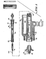
- valve seal 20 is intended to permit sealing of movable valve components, for example, valve needles, against the leakage of liquids, for example, coating materials maintained at relatively high pressure, and the like.
- the valve seal 20 is provided in a dispensing device (hereinafter sometimes "gun") 22.
- Gun 22 illustratively is of the general type of the Ransburg model REA 3, REA 4, REA 70, REA 90, REM and M-90 guns, available from ITW Ransburg, 320 Phillips Avenue, Toledo, Ohio, 43612-1493.
- the liquid is supplied from a source 24 to an input port 26 of the gun 22, and is supplied through a passageway 28 ( Fig.
- the liquid is dispensed from the gallery 30 under the control of the valve 32 to the nozzle 34 of the gun 22, where the liquid is atomized and dispensed.
- a trigger 36 ( Fig. 1 ) held by a gun 22 operator, controls the position of the valve 32.
- Valve 32 includes a seat 40 and a movable valve member 42. The position of the movable valve member 42 is controlled by the position of the trigger 36.
- the movable valve member 42 extends through a self-adjusting cartridge seal assembly 20 according to the invention, a rear needle seal retainer 48, an O-ring 50, a spring-loaded U-cup lip seal 52, a seal packing nut 54, and a seal spacer 56 to the rear 58 of the gun 22 barrel 60.
- the illustrated self-adjusting cartridge seal assembly 20 includes a front seal retainer 62, a seal holder 64 and a rear seal retainer 66.
- Front seal retainer 62 is shallow cup-shaped, with the cup opening toward the rear of gun 22.
- Seal holder 64 includes a somewhat smaller perimeter, forwardly opening cuplike forward portion 68, and a somewhat larger perimeter, rearwardly opening cuplike rearward portion 70.
- the internal dimensions of the portions 68, 70 are about the same.
- the internal dimension of rearward portion 70 includes a somewhat larger dimension groove 72 to receive a forward portion 74 of rear seal retainer 66.
- Rear seal retainer 66 further includes a somewhat smaller perimeter rearwardly extending portion 76.
- the main body portions 78, 80, 82 of front seal retainer 62, seal holder 64 and rear seal retainer 66 are all of substantially equal dimensions, and those dimensions are substantially the exterior dimensions of the cartridge, or packing tube, 84 ( Fig. 2 ) which along with cartridge seal assembly 20, rear needle seal retainer 48, O-ring 50, U-cup lip seal 52, packing nut 54, and seal spacer 56 are inserted into a passageway 85 provided therefor in barrel 60.
- Coaxial passageways 86 extend through all of front seal retainer 62, seal holder 64 and rear seal retainer 66. Passageways 86 all have substantially the dimensions of movable valve member 42 where movable valve member 42 passes through them.
- O-ring seals 88, 90 ( Fig. 6 ) are held in place in the cuplike interiors of portions 68, 70 of seal holder 64 by front seal retainer 62 and rear seal retainer 66.
- the interiors 92 of O-ring seals 88, 90 are smaller than the dimensions of movable valve member 42 where it passes through them, so that O-ring seals 88, 90 slidably seal against movable valve member 42.
- an O-ring seal 94 is provided in the space between the rearwardly extending lip 96 of front seal retainer 62 and the main body portion 80 of seal holder 64.
- front seal retainer 62 and seal holder 64 are constructed from 150 E natural Delrin brand acetal resin and rear seal retainer 66 is constructed from 30% carbon fiber filled Torlon brand polyamide-imide 7130.
- the carbon fiber filler renders rear seal retainer 66 electrically more non-insulative to assist in making electrical contact between an electrostatic charging needle 100 at the front of movable valve member 42 and a high-magnitude voltage cascade (not shown) mounted in a cavity 102 provided therefor in barrel 60.
- a low magnitude potential is supplied to the cascade from source 29.
- O-rings 88, 90, 94 illustratively are constructed from Kalrez brand resins, DuPont part number 2-004-4079.
Claims (9)
- Abgabevorrichtung (22) für strömungsfähiges Beschichtungsmaterial, die einen Einlass für strömungsfähiges Beschichtungsmaterial, einen Auslass für strömungsfähiges Beschichtungsmaterial und ein den Strom des strömungsfähigen Beschichtungsmaterials zwischen dem Einlass und dem Auslass steuerndes Ventil (32) aufweist, wobei das Ventil (32) ein bewegliches Ventilglied (42) und ein Ventilstellglied zum Bewegen des beweglichen Ventilglieds (42) zwischen einer Position, in der strömungsfähiges Beschichtungsmaterial zwischen dem Einlass und dem Auslass strömt, und einer Position, in der strömungsfähiges Beschichtungsmaterial nicht zwischen dem Einlass und dem Auslass fließt, enthält, wobei sich das bewegliche Ventilglied (42) in den Einlass erstreckt, und eine Dichtung (20) zum Abdichten des beweglichen Ventilglieds (42) aufweist, wobei sich das bewegliche Ventilglied in den Einlass erstreckt, wobei die Dichtung (20) eine Dichtungshalterung (62) näher am Einlass und einen Dichtungshalter (64) weiter vom Einlass entfernt enthält, wobei der Dichtungshalter (64) die Dichtungshalterung (62) in Eingriff nimmt,
dadurch gekennzeichnet, dass
die Vorrichtung eine Kassette (84) mit einer Außenabmessung enthält, wobei die Dichtungshalterung (62) und der Dichtungshalter (64) Hauptkörperteile enthalten, die Umfangsabmessungen aufweisen, welche im Wesentlichen gleich der Außenabmessung der Kassette (84) sind. - Vorrichtung nach Anspruch 1, wobei die Abgabevorrichtung (22) ein Gehäuse mit einem Ende neben dem Einlass enthält, das einen Anschlag aufweist, an den die Dichtungshalterung (62) anhält, wenn die Dichtung (20) in das Gehäuse eingesetzt wird.
- Vorrichtung nach Anspruch 1, weiterhin mit Durchgängen (86), die sich durch die Dichtungshalterung (62) und den Dichtungshalter (64) erstrecken, wobei sich das bewegliche Ventilglied (42) beweglich durch die Durchgänge (86) erstreckt.
- Vorrichtung nach Anspruch 3, wobei die Durchgänge (86) Querschnittsabmessungen quer zur ersten und zweiten Richtung aufweisen, wobei diese Querschnittsabmessungen im Wesentlichen denen des beweglichen Ventilglieds (42) quer zur ersten und zweiten Richtung entsprechen, wobei sich das bewegliche Ventilglied (42) durch die Durchgänge (86) und eine erste Dichtung zwischen der Dichtungshalterung (62) und dem Dichtungshalter (64) erstreckt, wobei die erste Dichtung zum Durchgang (86) freiliegt und das bewegliche Ventilglied (42) gleitend und abdichtend aufnimmt.
- Vorrichtung nach Anspruch 4, weiterhin mit einer O-Ring-Dichtung (90), die zwischen der Dichtungshalterung (62) und dem Dichtungshalter (64) erfasst ist, wobei die O-Ring-Dichtung (90) zu den Durchgängen (86) freiliegt und das bewegliche Ventilglied (42) gleitend und abdichtend aufnimmt.
- Vorrichtung nach Anspruch 4, wobei der Dichtungshalter (64) einen in etwa schalenförmigen Teil enthält, wobei die Vorrichtung weiterhin eine O-Ring-Dichtung aufweist, die in dem in etwa schalenförmigen Teil vorgesehen ist, wobei die O-Ring-Dichtung zu den Durchgängen (86) freiliegt und das bewegliche Ventilglied (42) gleitend und abdichtend aufnimmt.
- Vorrichtung nach Anspruch 4, weiterhin mit einer O-Ring-Dichtung (88), die zwischen der Dichtungshalterung (62) und dem Dichtungshalter (64) vorgesehen ist.
- Vorrichtung nach einem der Ansprüche 1 bis 7, wobei die Dichtungshalterung (62) und der Dichtungshalter (64) aus Acetalharzen hergestellt sind.
- Vorrichtung nach einem der Ansprüche 1 bis 8, wobei das bewegliche Ventilglied (42) eine Elektrode enthält, die sich durch das Ventil zum Auslass erstreckt, wobei die Vorrichtung weiterhin eine Hochspannungsquelle enthält, die mit der Elektrode verbunden ist, um durch den Auslass passierendes Beschichtungsmaterial einer elektrischen Ladung auszusetzen.
Applications Claiming Priority (4)
| Application Number | Priority Date | Filing Date | Title |
|---|---|---|---|
| US40731702P | 2002-08-30 | 2002-08-30 | |
| US407317P | 2002-08-30 | ||
| US10/435,790 US6916023B2 (en) | 2002-08-30 | 2003-05-12 | Self-adjusting cartridge seal |
| US435790 | 2003-05-12 |
Publications (2)
| Publication Number | Publication Date |
|---|---|
| EP1393814A1 EP1393814A1 (de) | 2004-03-03 |
| EP1393814B1 true EP1393814B1 (de) | 2008-04-02 |
Family
ID=31498784
Family Applications (1)
| Application Number | Title | Priority Date | Filing Date |
|---|---|---|---|
| EP03019137A Expired - Fee Related EP1393814B1 (de) | 2002-08-30 | 2003-08-23 | Selbsteinstellende Kassettendichtung |
Country Status (8)
| Country | Link |
|---|---|
| US (1) | US6916023B2 (de) |
| EP (1) | EP1393814B1 (de) |
| JP (1) | JP2004089997A (de) |
| KR (1) | KR20040019923A (de) |
| CN (1) | CN1272111C (de) |
| CA (1) | CA2438405C (de) |
| DE (1) | DE60320069T2 (de) |
| MX (1) | MXPA03007793A (de) |
Families Citing this family (16)
| Publication number | Priority date | Publication date | Assignee | Title |
|---|---|---|---|---|
| ES2366657T3 (es) * | 2007-01-25 | 2011-10-24 | Nordson Corporation | Aparato para dispensar material líquido. |
| US20090206182A1 (en) * | 2008-01-25 | 2009-08-20 | Abb Inc. | Rotary Atomizer with an Improved Valve |
| GB2457489B (en) * | 2008-02-15 | 2012-10-31 | Itw Ltd | Adjustable needle seal |
| GB2457886A (en) * | 2008-02-26 | 2009-09-02 | Itw Ltd | Ball connector between manifold and spray head |
| US8590817B2 (en) * | 2008-03-10 | 2013-11-26 | Illinois Tool Works Inc. | Sealed electrical source for air-powered electrostatic atomizing and dispensing device |
| US8770496B2 (en) | 2008-03-10 | 2014-07-08 | Finishing Brands Holdings Inc. | Circuit for displaying the relative voltage at the output electrode of an electrostatically aided coating material atomizer |
| US7988075B2 (en) | 2008-03-10 | 2011-08-02 | Illinois Tool Works Inc. | Circuit board configuration for air-powered electrostatically aided coating material atomizer |
| USD608858S1 (en) | 2008-03-10 | 2010-01-26 | Illinois Tool Works Inc. | Coating material dispensing device |
| US8016213B2 (en) * | 2008-03-10 | 2011-09-13 | Illinois Tool Works Inc. | Controlling temperature in air-powered electrostatically aided coating material atomizer |
| US7926748B2 (en) * | 2008-03-10 | 2011-04-19 | Illinois Tool Works Inc. | Generator for air-powered electrostatically aided coating dispensing device |
| US8496194B2 (en) | 2008-03-10 | 2013-07-30 | Finishing Brands Holdings Inc. | Method and apparatus for retaining highly torqued fittings in molded resin or polymer housing |
| US7918409B2 (en) * | 2008-04-09 | 2011-04-05 | Illinois Tool Works Inc. | Multiple charging electrode |
| US8225968B2 (en) | 2009-05-12 | 2012-07-24 | Illinois Tool Works Inc. | Seal system for gear pumps |
| CN107803287A (zh) * | 2017-12-08 | 2018-03-16 | 浙江奥利达气动工具股份有限公司 | 具有阀门密封结构的喷枪 |
| CN109264661A (zh) * | 2018-09-20 | 2019-01-25 | 包头钢铁(集团)有限责任公司 | 一种矿车燃油加油枪 |
| CN116891210B (zh) * | 2023-09-04 | 2023-12-01 | 济南弗莱德科技有限公司 | 一种通过二次油气回收实现加油站油气零排放的装置 |
Family Cites Families (18)
| Publication number | Priority date | Publication date | Assignee | Title |
|---|---|---|---|---|
| US2690360A (en) * | 1951-04-17 | 1954-09-28 | Foxboro Co | Pressuretight seal |
| US3169882A (en) * | 1960-10-05 | 1965-02-16 | Ransburg Electro Coating Corp | Electrostatic coating methods and apparatus |
| US3194502A (en) * | 1962-11-14 | 1965-07-13 | American Type Founders Co Inc | Air operated spray device having flexible packing means |
| US4824026A (en) * | 1986-08-06 | 1989-04-25 | Toyota Jidosha Kabushiki Kaisha And Ransburg-Gema K.K. | Air atomizing electrostatic coating gun |
| US4796895A (en) | 1988-01-25 | 1989-01-10 | General Motors Corporation | Self adjusting seal for high pressure supply line |
| US4958769A (en) | 1988-12-27 | 1990-09-25 | Ford Motor Company | Compressed O-ring spray gun needle valve seal |
| US4911406A (en) * | 1989-01-11 | 1990-03-27 | Accor Technology, Inc. | Fluid conduit coupling apparatus |
| GB2239929A (en) | 1990-01-09 | 1991-07-17 | Grace W R & Co | Improved seal |
| DE4009168A1 (de) | 1990-03-22 | 1991-09-26 | Walther Spritz Lackiersyst | Spritzpistole |
| AT394425B (de) | 1990-06-21 | 1992-03-25 | Vaillant Gmbh | Wasserschalter |
| US5099882A (en) * | 1991-01-11 | 1992-03-31 | National Coupling Company, Inc. | Pressure balanced hydraulic coupling with metal seals |
| US5340228A (en) | 1992-05-22 | 1994-08-23 | The Flagship Group Ii, Inc. | Self-adjusting soft seal cap for fine point craft paint applicators |
| US5267533A (en) | 1992-07-20 | 1993-12-07 | The Babcock & Wilcox Company | Self-adjusting packing gland for sootblower |
| FR2693924B1 (fr) | 1992-07-21 | 1994-09-23 | Sicmo | Pistolet à peinture, basse pression dont la tête de pulvérisation est perfectionnée. |
| AU5349194A (en) | 1993-03-25 | 1994-10-11 | Nai Anchorlok, Inc. | Sealed bearing for fluid-operated brake actuator |
| US6062570A (en) * | 1996-02-16 | 2000-05-16 | Barber-Colman | Stem sealing system for broad temperature ranges |
| JP3384692B2 (ja) * | 1996-07-31 | 2003-03-10 | 三菱電機株式会社 | 筒内噴射用燃料噴射弁 |
| US5983934A (en) * | 1998-01-16 | 1999-11-16 | National Coupling Company, Inc. | Undersea hydraulic coupling with three retained seals |
-
2003
- 2003-05-12 US US10/435,790 patent/US6916023B2/en not_active Expired - Fee Related
- 2003-08-19 JP JP2003295372A patent/JP2004089997A/ja active Pending
- 2003-08-23 DE DE60320069T patent/DE60320069T2/de not_active Expired - Fee Related
- 2003-08-23 EP EP03019137A patent/EP1393814B1/de not_active Expired - Fee Related
- 2003-08-25 KR KR1020030058829A patent/KR20040019923A/ko not_active Application Discontinuation
- 2003-08-27 CA CA002438405A patent/CA2438405C/en not_active Expired - Fee Related
- 2003-08-28 MX MXPA03007793A patent/MXPA03007793A/es active IP Right Grant
- 2003-08-29 CN CNB031563058A patent/CN1272111C/zh not_active Expired - Fee Related
Also Published As
| Publication number | Publication date |
|---|---|
| JP2004089997A (ja) | 2004-03-25 |
| CA2438405C (en) | 2007-01-23 |
| CN1485144A (zh) | 2004-03-31 |
| EP1393814A1 (de) | 2004-03-03 |
| KR20040019923A (ko) | 2004-03-06 |
| MXPA03007793A (es) | 2004-03-05 |
| CA2438405A1 (en) | 2004-02-29 |
| US20040041349A1 (en) | 2004-03-04 |
| DE60320069T2 (de) | 2009-05-14 |
| US6916023B2 (en) | 2005-07-12 |
| DE60320069D1 (de) | 2008-05-15 |
| CN1272111C (zh) | 2006-08-30 |
Similar Documents
| Publication | Publication Date | Title |
|---|---|---|
| EP1393814B1 (de) | Selbsteinstellende Kassettendichtung | |
| US4294411A (en) | Electrostatic spray gun | |
| CA2585121C (en) | Indexing valve | |
| US6685106B1 (en) | Paint spraying device | |
| US6854672B2 (en) | Air-assisted air valve for air atomized spray guns | |
| US5050804A (en) | Shaft seal for portable paint gun | |
| EP0934776A1 (de) | Sprühpistole mit gleichzeitiger Kontrolle des Fluid- und Luftventils | |
| EP0467334B1 (de) | Tragbare Farbspritzpistole | |
| US20070034268A1 (en) | Air valve for spray guns | |
| JP3471234B2 (ja) | 自動スプレーガンのパッキン構造 | |
| JP2022188871A (ja) | 塗装ガン | |
| WO2024003876A1 (en) | Spray gun system with resilient flow control valve | |
| JPS6331725Y2 (de) | ||
| CN116474970A (zh) | 一种气动喷枪 | |
| JPH02180660A (ja) | 塗装機用塗料色替装置 | |
| JPH0646522Y2 (ja) | スプレイガン | |
| JP2566404B2 (ja) | 塗装用ハンドガン | |
| EP2167858B1 (de) | Länglicher bauschverschluss für eine sprühpistole | |
| JPS6380868A (ja) | 塗料用スプレイガン | |
| JPH0716506A (ja) | スプレーガン | |
| JP2000325836A (ja) | 静電塗装装置 | |
| KR960040453A (ko) | 스프레이 건 |
Legal Events
| Date | Code | Title | Description |
|---|---|---|---|
| PUAI | Public reference made under article 153(3) epc to a published international application that has entered the european phase |
Free format text: ORIGINAL CODE: 0009012 |
|
| AK | Designated contracting states |
Kind code of ref document: A1 Designated state(s): AT BE BG CH CY CZ DE DK EE ES FI FR GB GR HU IE IT LI LU MC NL PT RO SE SI SK TR |
|
| AX | Request for extension of the european patent |
Extension state: AL LT LV MK |
|
| 17P | Request for examination filed |
Effective date: 20040707 |
|
| AKX | Designation fees paid |
Designated state(s): DE FR IT |
|
| 17Q | First examination report despatched |
Effective date: 20070322 |
|
| GRAP | Despatch of communication of intention to grant a patent |
Free format text: ORIGINAL CODE: EPIDOSNIGR1 |
|
| GRAS | Grant fee paid |
Free format text: ORIGINAL CODE: EPIDOSNIGR3 |
|
| GRAA | (expected) grant |
Free format text: ORIGINAL CODE: 0009210 |
|
| AK | Designated contracting states |
Kind code of ref document: B1 Designated state(s): DE FR IT |
|
| REF | Corresponds to: |
Ref document number: 60320069 Country of ref document: DE Date of ref document: 20080515 Kind code of ref document: P |
|
| PGFP | Annual fee paid to national office [announced via postgrant information from national office to epo] |
Ref country code: IT Payment date: 20080825 Year of fee payment: 6 Ref country code: FR Payment date: 20080818 Year of fee payment: 6 |
|
| ET | Fr: translation filed | ||
| PGFP | Annual fee paid to national office [announced via postgrant information from national office to epo] |
Ref country code: DE Payment date: 20080930 Year of fee payment: 6 |
|
| PLBE | No opposition filed within time limit |
Free format text: ORIGINAL CODE: 0009261 |
|
| STAA | Information on the status of an ep patent application or granted ep patent |
Free format text: STATUS: NO OPPOSITION FILED WITHIN TIME LIMIT |
|
| 26N | No opposition filed |
Effective date: 20090106 |
|
| REG | Reference to a national code |
Ref country code: FR Ref legal event code: ST Effective date: 20100430 |
|
| PG25 | Lapsed in a contracting state [announced via postgrant information from national office to epo] |
Ref country code: FR Free format text: LAPSE BECAUSE OF NON-PAYMENT OF DUE FEES Effective date: 20090831 Ref country code: DE Free format text: LAPSE BECAUSE OF NON-PAYMENT OF DUE FEES Effective date: 20100302 |
|
| PG25 | Lapsed in a contracting state [announced via postgrant information from national office to epo] |
Ref country code: IT Free format text: LAPSE BECAUSE OF NON-PAYMENT OF DUE FEES Effective date: 20090823 |