EP1392974B1 - Silencieux d'aspiration pour compresseur hermetique alternatif - Google Patents
Silencieux d'aspiration pour compresseur hermetique alternatif Download PDFInfo
- Publication number
- EP1392974B1 EP1392974B1 EP01940026.6A EP01940026A EP1392974B1 EP 1392974 B1 EP1392974 B1 EP 1392974B1 EP 01940026 A EP01940026 A EP 01940026A EP 1392974 B1 EP1392974 B1 EP 1392974B1
- Authority
- EP
- European Patent Office
- Prior art keywords
- duct portion
- suction muffler
- acoustic chamber
- chamber
- muffler according
- Prior art date
- Legal status (The legal status is an assumption and is not a legal conclusion. Google has not performed a legal analysis and makes no representation as to the accuracy of the status listed.)
- Expired - Lifetime
Links
Images

Classifications
-
- F—MECHANICAL ENGINEERING; LIGHTING; HEATING; WEAPONS; BLASTING
- F04—POSITIVE - DISPLACEMENT MACHINES FOR LIQUIDS; PUMPS FOR LIQUIDS OR ELASTIC FLUIDS
- F04B—POSITIVE-DISPLACEMENT MACHINES FOR LIQUIDS; PUMPS
- F04B39/00—Component parts, details, or accessories, of pumps or pumping systems specially adapted for elastic fluids, not otherwise provided for in, or of interest apart from, groups F04B25/00 - F04B37/00
- F04B39/0027—Pulsation and noise damping means
- F04B39/0055—Pulsation and noise damping means with a special shape of fluid passage, e.g. bends, throttles, diameter changes, pipes
- F04B39/0066—Pulsation and noise damping means with a special shape of fluid passage, e.g. bends, throttles, diameter changes, pipes using sidebranch resonators, e.g. Helmholtz resonators
-
- F—MECHANICAL ENGINEERING; LIGHTING; HEATING; WEAPONS; BLASTING
- F04—POSITIVE - DISPLACEMENT MACHINES FOR LIQUIDS; PUMPS FOR LIQUIDS OR ELASTIC FLUIDS
- F04B—POSITIVE-DISPLACEMENT MACHINES FOR LIQUIDS; PUMPS
- F04B39/00—Component parts, details, or accessories, of pumps or pumping systems specially adapted for elastic fluids, not otherwise provided for in, or of interest apart from, groups F04B25/00 - F04B37/00
- F04B39/0027—Pulsation and noise damping means
- F04B39/0055—Pulsation and noise damping means with a special shape of fluid passage, e.g. bends, throttles, diameter changes, pipes
- F04B39/0072—Pulsation and noise damping means with a special shape of fluid passage, e.g. bends, throttles, diameter changes, pipes characterised by assembly or mounting
-
- Y—GENERAL TAGGING OF NEW TECHNOLOGICAL DEVELOPMENTS; GENERAL TAGGING OF CROSS-SECTIONAL TECHNOLOGIES SPANNING OVER SEVERAL SECTIONS OF THE IPC; TECHNICAL SUBJECTS COVERED BY FORMER USPC CROSS-REFERENCE ART COLLECTIONS [XRACs] AND DIGESTS
- Y10—TECHNICAL SUBJECTS COVERED BY FORMER USPC
- Y10S—TECHNICAL SUBJECTS COVERED BY FORMER USPC CROSS-REFERENCE ART COLLECTIONS [XRACs] AND DIGESTS
- Y10S417/00—Pumps
- Y10S417/902—Hermetically sealed motor pump unit
Definitions
- the present invention refers to a suction muffler for a reciprocating hermetic compressor, particularly of the type used in small refrigeration systems in the region where the refrigerant gas is supplied to the hermetic compressor.
- the reciprocating hermetic compressors present, at the suction side thereof, an acoustic dampening system (acoustic filters or suction mufflers), which is provided inside the shell and which conducts the gas coming from the suction line to the suction valve.
- an acoustic dampening system acoustic filters or suction mufflers
- This component has several important functions to the adequate operation of the compressor, such as gas directing, acoustic dampening and, in some cases, thermal insulation of the gas being drawn into the cylinder.
- the adequate thermal insulation of the gas being drawn is important to improve the volumetric and energetic efficiencies of the compressor.
- the gas temperature is increased, due to heat transferred thereto from the several hot sources existing inside the compressor.
- the temperature increase of the gas causes an increase in its specific volume and consequently reduces the mass flow of the refrigerant pumped by the compressor. Since the refrigeration capacity of the compressor is directly proportional to the mass flow, reducing said flow results in efficiency loss.
- the current mufflers are usually produced in a material of low thermal conductivity, such as for example, resins, plastic, having good thermal insulation property.
- the suction mufflers constructed of injected plastic material and comprising a hollow body, which is provided with gas inlet and gas outlet nozzles and, internally, with a plurality of chambers disposed in a consecutive arrangement and in a linear sequence, and which are maintained in fluid communication in relation to each other and to the gas inlet of the compressor through a duct having an end connected and opened to the gas inlet nozzle of the hollow body; median windows, which are longitudinally spaced from each other and opened to respective chambers; and an opposite end opened to a last chamber of the linear sequence and which is maintained opened to the gas outlet of the hollow body.
- US-A-5733106 discloses a suction muffler for a reciprocating hermetic compressor comprising a hollow body having a gas inlet and a gas outlet and an upper acoustic chamber located above a baffle.
- the refrigerant is sucked in through a suction inlet and the baffle is provided with through holes for conducting the refrigerant into a lower chamber from which it enters a double piping arrangement in fluid communication with the gas outlet.
- the suction muffler for a reciprocating hermetic compressor comprises a gas inlet, a gas outlet, a first upper acoustic chamber and a second lower acoustic chamber in a side-by-side arrangement.
- the whole muffler consists of three separate parts, namely an upper part, an insert being open at its top and a lower portion which includes the inlet.
- a first duct portion provided through the second acoustic chamber maintains a fluid communication between the first and the second acoustic chambers and with the gas inlet, and a second duct portion extending into the inside of the first acoustic chamber maintains a fluid communication of the first acoustic chamber with the gas outlet.
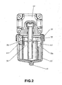
- the suction muffler of the present invention comprises a hollow body 10 usually obtained in a material of low thermal conductivity, for example with a rectangular cross-section, and which is closed by an upper cover 10 to be seated on the upper edge of the hollow body 10 and there affixed by any adequate means, such as for example a pair of clamps 30 fitted by elastic deformation into respective lugs 11 and 21 provided in both the hollow body 10 and the cover 20.
- the hollow body 10 is provided with a gas inlet 12, in fluid communication with the gas supply to the compressor and aligned with the suction tube of the compressor (not illustrated), and a gas outlet 14 in fluid communication with the suction side of the compressor.
- the cover 20 incorporates, superiorly and externally, a gas outlet nozzle 22, in the form of a tubular extension, with its free end shaped to be adapted to the suction orifice of a valve plate 40 of the head of the hermetic compressor.
- the hollow body 10 defines a plurality of chambers, disposed in surrounding superposed layers, for example in an eccentric arrangement, comprising a first innermost acoustic chamber 50 in fluid communication with the gas inlet 12 and the gas outlet 14 of the hollow body 10, and a second acoustic chamber surrounding at least partially the first acoustic chamber 50 and in fluid communication with at least one of the parts defined by said first acoustic chamber 50 and by the gas inlet 12 of the hollow body 10.
- the hollow body 10 defines only two acoustic chambers, the second acoustic chamber 51 being maintained in direct fluid communication with the gas inlet 12 and in restrict and pressure equalizing fluid communication with the inside of the compressor shell.
- the hollow body 10 is provided, in a lower wall 10a, with a restricting orifice 15, for drainage of lubricant oil and by which is obtained said pressure equalization.
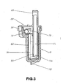
- the first acoustic chamber 50 is defined internal to a shell 60, which is formed for example by a two-piece body and provided inside the hollow body 10, the second acoustic chamber 51 being defined external to said shell 60 and internal to said hollow body 10.
- the fluid communication between the first and the second acoustic chambers 50, 51 is maintained through a first duct portion 70, which is provided through the second acoustic chamber 51 and connected to the gas inlet 12 of the hollow body 10 and provided with at least one window 72, which is opened to the second acoustic chamber 51 and through which is achieved the direct fluid communication between said second acoustic chamber and the gas inlet 12 of the hollow body 10.
- the second acoustic chamber 51 in a constructive option of the present invention, may keep direct fluid communication with the first acoustic chamber 50, being provided in a wall of the shell 60, maintaining indirect fluid communication with the gas inlet 12 of the hollow body 10, or may be also defined, in another non-illustrated constructive option, by the discontinuity of the duct 40, communicating said gas inlet 12 with the first acoustic chamber 50.
- the plurality of chambers of the hollow body 10 may further comprise (though not illustrated) at least one heat insulating chamber, which is provided in order to surround, at least partially and adjacently, at least one of the first and second chambers 50, 51, each heat insulating chamber being maintained only in restrict and pressure equalizing fluid communication with the inside of the shell (60) of the compressor.
- This equalizing fluid communication can be obtained, for example, by a restricting orifice provided in each chamber, for allowing the oil to pass from the innermost chamber to the outermost chamber and thence to the shell of the compressor.
- the first duct portion 70 is continuous through said heat insulating chamber, in order to prevent the gas admitted by said first duct portion 70 from reaching the internal volume of these chambers.
- each one of the surrounding chambers also defines a respective heat insulating chamber in relation to the surrounded chamber.
- the first acoustic chamber 50 is maintained in fluid communication with the gas outlet 14 of the hollow body 10 through a second duct portion 71 tightly mounted into an outlet orifice 61 of the shell 60 dimensioned for the tight passage of an inlet end 71a of the second duct portion 71 and opened to the inside of the first acoustic chamber 50, upon mounting said second duct portion 71 inside the first acoustic chamber 50.
- the second duct portion 71 presents a certain preferred extension, for instance substantially rectilinear which, as illustrated, is provided inside the first acoustic chamber 50, so that the respective inlet end 71a thereof is disposed close to an outlet end 70a of the first duct portion 70, terminating, for example, in the form of a deflector and having its axis parallel to the axis of said inlet end 71a.
- the second duct portion with variations in the shape (not rectilinear), extension and positioning of said portion inside the first acoustic chamber 50, without said modifications affecting the performance of the suction muffler of the present invention.
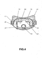
- the first duct portion 70 is incorporated to the walls of the first acoustic chamber 50, which is for example in two pieces, with each half of its body being adjacent to an enlarged upper portion 50 of the first acoustic chamber 50, in order to define a respective half of the extension of said first duct portion 70.
- the shell 60 carries in a gas inlet, a nozzle in the shape of a cornet 64 opened to the inside of the compressor and aligned with the suction tube.
- the first duct portion 70 presents a window 72 defined by an extension discontinuity in one of the walls of the body of the first acoustic chamber 50 that defines a corresponding extension of said first duct portion 70.
- the parts of the body defining the first duct portion 70 are seated and attached to each other, by being fitted inside the walls of the adjacent surrounding chamber, which in this construction is the second acoustic chamber 51.
- the fixation between the parts defining the body of the first duct portion 70 is achieved by fitting a guide element 80 provided in one of the parts defined by the hollow body 10 and the shell 60, for example in an external wall of one of the parts of said first acoustic chamber 50, into a rail (not illustrated) provided in the other of said parts, for example in one of the internal walls of the second acoustic chamber 51.
- the gas admitted by the suction muffler through the cornet 64 is directly conducted to the inside of the first acoustic chamber 50, from which it is drawn to the inside of the compressor cylinder (not illustrated) by means of the second duct portion 71.
- the arrangement of the surrounding chambers of the present invention increases the resistance to the transfer of heat generated by the compressor and transmitted to the gas drawn thereby, since the gas flow has to cross the wall of each outermost chamber, which is usually in a material of low thermal conductivity, the thickness of the gas mass contained in the outermost chamber, and the wall of the innermost chamber, before reaching the innermost acoustic chamber and thence the interior of the cylinder.
- the geometry of the innermost acoustic chamber allows the temporary formation of a cold gas volume, available to suction, which allows the acoustic effect of cylinder over-filling, improving the compressor efficiency.
- a further advantage of the present solution is that the arrangement of the surrounding chambers allows the noise transmission to be attenuated in the direction of transmission. Part of the noise generated by operation of the suction valve is transmitted by the walls that form the muffler, which vibrate upon operation of the compressor. Thus, the existence of a gas volume between the immediately adjacent walls of the chambers of the present construction attenuates said transmission.
Landscapes
- Engineering & Computer Science (AREA)
- Mechanical Engineering (AREA)
- General Engineering & Computer Science (AREA)
- Compressor (AREA)
Claims (13)
- Silencieux d'aspiration pour un compresseur alternatif hermétique, comprenant :- un corps creux (10) ayant une admission de gaz (12) et un refoulement de gaz (22),- une enveloppe (60) étant agencée à l'intérieur du corps creux (10), ayant un intérieur qui définit une première chambre acoustique la plus interne (50) en communication fluidique avec le refoulement de gaz (22), et ayant également un orifice de refoulement (61),- au moins une seconde chambre acoustique (51) étant définie externe à ladite enveloppe (60) et interne audit corps creux (10) et entourant au moins partiellement ladite première chambre acoustique (50),- des première et seconde parties de conduite (70, 71),ladite première partie de conduite (70) étant incorporée dans une partie des parois qui définissent la première chambre acoustique (50) et agencée à travers la seconde chambre acoustique (51), maintenant une communication fluidique entre lesdites première et seconde chambres acoustiques (50, 51) et avec l'admission de gaz (12), et étant dotée d'au moins une fenêtre (72) ouverte vers la seconde chambre acoustique (51) et prévue dans l'une des parois du corps de la première chambre acoustique (50) en une position définissant ladite première partie de conduite (70),
ladite seconde partie de conduite (71) étant étendue à l'intérieur de la première chambre acoustique (50), étant montée fermement dans l'orifice de refoulement (61) de l'enveloppe (60) et maintenant une communication fluidique de la première chambre acoustique (50) avec le refoulement de gaz (22). - Silencieux d'aspiration selon la revendication 1, caractérisé en ce qu'il comprend au moins une chambre d'isolation thermique, qui est agencée afin d'entourer au moins partiellement et de façon adjacente la première et/ou la seconde chambre acoustique (50 ; 51), chaque chambre d'isolation thermique étant maintenue uniquement en communication fluidique restreinte et d'égalisation de pression avec l'intérieur de l'enveloppe du compresseur.
- Silencieux d'aspiration selon la revendication 2, caractérisé en ce que la première partie de conduite (70) est continue à travers la chambre d'isolation thermique.
- Silencieux d'aspiration selon la revendication 3, caractérisé en ce que la première partie de conduite (70) s'étend vers l'intérieur de la première chambre acoustique (50).
- Silencieux d'aspiration selon la revendication 4, caractérisé en ce que la seconde partie de conduite (71) a une partie importante de son extension à l'intérieur de la première chambre acoustique (50).
- Silencieux d'aspiration selon la revendication 5, caractérisé en ce que la première partie de conduite (70) a une extrémité de refoulement (70a) agencée proche d'une extrémité d'admission (71 a) de la seconde partie de conduite (71).
- Silencieux d'aspiration selon la revendication 6, caractérisé en ce que l'extrémité de refoulement (70a) de la première partie de conduite (70) a son axe parallèle à celui de l'extrémité d'admission (71 a) de la seconde partie de conduite (71).
- Silencieux d'aspiration selon la revendication 7, caractérisé en ce que la seconde partie de conduite (71) est rectiligne dans une partie substantielle de son extension interne à la première chambre acoustique (50).
- Silencieux d'aspiration selon la revendication 8, caractérisé en ce que l'extrémité de refoulement (70a) de la première partie de conduite (70) est sous la forme d'un déflecteur.
- Silencieux d'aspiration selon la revendication 9, caractérisé en ce que l'enveloppe (60) est formée en deux pièces, qui sont assises et fixées l'une à l'autre.
- Silencieux d'aspiration selon la revendication 10, caractérisé en ce que la fixation entre les deux pièces du corps de l'enveloppe (60) est obtenue lors de leur installation à l'intérieur des parois de la chambre environnante adjacente.
- Silencieux d'aspiration selon la revendication 11, caractérisé en ce que ladite fixation est obtenue par l'installation d'un élément de guidage (80) agencé dans l'une des parties définies par le corps creux (10) et l'enveloppe (60) dans un rail agencé dans l'autre desdites parties.
- Silencieux d'aspiration selon la revendication 1, caractérisé en ce que les chambres sont agencées dans des couches superposées environnantes dans un agencement excentrique.
Applications Claiming Priority (1)
| Application Number | Priority Date | Filing Date | Title |
|---|---|---|---|
| PCT/BR2001/000072 WO2002101239A1 (fr) | 2001-06-08 | 2001-06-08 | Silencieux d'aspiration pour compresseur hermetique alternatif |
Publications (2)
| Publication Number | Publication Date |
|---|---|
| EP1392974A1 EP1392974A1 (fr) | 2004-03-03 |
| EP1392974B1 true EP1392974B1 (fr) | 2015-08-05 |
Family
ID=3946499
Family Applications (1)
| Application Number | Title | Priority Date | Filing Date |
|---|---|---|---|
| EP01940026.6A Expired - Lifetime EP1392974B1 (fr) | 2001-06-08 | 2001-06-08 | Silencieux d'aspiration pour compresseur hermetique alternatif |
Country Status (7)
| Country | Link |
|---|---|
| US (1) | US7147082B2 (fr) |
| EP (1) | EP1392974B1 (fr) |
| JP (1) | JP4956703B2 (fr) |
| KR (1) | KR100838266B1 (fr) |
| CN (1) | CN1318758C (fr) |
| SK (1) | SK287803B6 (fr) |
| WO (1) | WO2002101239A1 (fr) |
Families Citing this family (16)
| Publication number | Priority date | Publication date | Assignee | Title |
|---|---|---|---|---|
| BR0105694B1 (pt) * | 2001-10-29 | 2009-05-05 | filtro de sucção para compressor hermético alternativo. | |
| US7578659B2 (en) * | 2005-01-31 | 2009-08-25 | York International Corporation | Compressor discharge muffler |
| AT8401U1 (de) * | 2005-03-31 | 2006-07-15 | Acc Austria Gmbh | Kältemittelverdichter |
| BRPI0601716B1 (pt) * | 2006-05-03 | 2018-09-25 | Empresa Brasileira De Compressores S A Embraco | arranjo de ressonadores em filtro acústico para compressor de refrigeração |
| BRPI0700748A (pt) * | 2007-02-13 | 2008-09-30 | Whirlpool Sa | arranjo construtivo de filtro acústico para um compressor de refrigeração |
| US8323556B2 (en) * | 2009-09-30 | 2012-12-04 | Ford Global Technologies, Llc | Manufacture of an acoustic silencer |
| CN102297118B (zh) * | 2011-09-30 | 2013-10-09 | 黄石东贝电器股份有限公司 | 分离式隔热排气消音装置及采用其的制冷压缩机 |
| BRPI1105162B1 (pt) | 2011-12-15 | 2021-08-24 | Embraco Indústria De Compressores E Soluções Em Refrigeração Ltda. | Filtro acústico para compressor alternativo |
| CN102720653B (zh) * | 2012-06-20 | 2014-08-20 | 常熟市天银机电股份有限公司 | 压缩机吸气消音器 |
| CN104797819A (zh) * | 2012-10-05 | 2015-07-22 | 阿塞里克股份有限公司 | 包括排气消声器的封闭式压缩机 |
| BR102013019311B1 (pt) | 2013-07-30 | 2021-10-13 | Embraco Indústria De Compressores E Soluções Em Refrigeração Ltda | Dispositivo atenuador acústico para compressores |
| KR102201629B1 (ko) * | 2014-06-26 | 2021-01-12 | 엘지전자 주식회사 | 리니어 압축기 및 이를 포함하는 냉장고 |
| BR102015006163A2 (pt) * | 2015-03-19 | 2016-10-18 | Whirlpool Sa | compressor alternativo incluindo filtro acústico de sucção |
| CN105134556B (zh) * | 2015-10-10 | 2018-03-23 | 青岛海尔股份有限公司 | 压缩机及其吸气消音器 |
| JP6514727B2 (ja) * | 2017-03-08 | 2019-05-15 | 株式会社Subaru | 消音装置 |
| CN110985341A (zh) * | 2019-12-12 | 2020-04-10 | 珠海格力节能环保制冷技术研究中心有限公司 | 消音器、压缩机和家用电器 |
Family Cites Families (22)
| Publication number | Priority date | Publication date | Assignee | Title |
|---|---|---|---|---|
| GB543055A (en) * | 1940-07-04 | 1942-02-09 | Joseph George Blanchard | Improvements in or relating to silencers for the passage of gaseous currents |
| US2955671A (en) * | 1954-08-25 | 1960-10-11 | Leistritz Hans Karl | Induction silencers for internal combustion engine carburetors |
| DE2908506C2 (de) * | 1979-03-05 | 1985-01-31 | Roth Technik GmbH, 7560 Gaggenau | Schalldämpfer für Verbrennungskraftmaschinen |
| JPS60195323A (ja) | 1984-03-19 | 1985-10-03 | Tokico Ltd | 消音器 |
| BR8602173A (pt) * | 1986-05-02 | 1987-12-22 | Brasil Compressores Sa | Aperfeicoamento em sistema de succao de compressor hermetico de refrigeracao |
| JP2845561B2 (ja) * | 1990-04-06 | 1999-01-13 | 松下冷機株式会社 | 密閉型電動圧縮機 |
| BR9102288A (pt) * | 1991-05-28 | 1993-01-05 | Brasileira S A Embraco Empresa | Conjunto abafador de succao para compressor hermetico |
| KR200141490Y1 (ko) * | 1993-04-24 | 1999-05-15 | 김광호 | 압축기의소음감쇠장치 |
| JP2895407B2 (ja) * | 1994-12-01 | 1999-05-24 | 本田技研工業株式会社 | 吸気消音装置 |
| KR0143142B1 (ko) * | 1995-03-07 | 1998-08-01 | 김광호 | 왕복동 압축기의 실린더장치 |
| DE19522383C2 (de) * | 1995-06-23 | 1997-06-19 | Danfoss Compressors Gmbh | Saugschalldämpfer für einen Kältemittelkompressor |
| KR0175891B1 (ko) * | 1995-07-29 | 1999-10-01 | 윤종용 | 압축기 |
| US5804777A (en) * | 1995-11-02 | 1998-09-08 | Lg Electronics Inc. | Suction noise muffler for hermetic compressor |
| KR19980027501U (ko) * | 1996-11-16 | 1998-08-05 | 박병재 | 자동차의 연료탱크 구조 |
| KR100210091B1 (ko) * | 1997-03-14 | 1999-07-15 | 윤종용 | 압축기의 소음감쇠장치 |
| KR200147723Y1 (ko) * | 1997-03-31 | 1999-06-15 | 윤종용 | 왕복동형 압축기 |
| KR100269951B1 (ko) * | 1997-11-05 | 2000-10-16 | 배길성 | 압축기의 흡입 머플러 |
| BR9900463A (pt) * | 1999-02-26 | 2000-08-29 | Brasil Compressores Sa | Abafador de sucção para compressor hermético |
| CN1120299C (zh) * | 1999-02-26 | 2003-09-03 | 恩布拉科欧州有限公司 | 用于密封的制冷压缩机的消音器 |
| DE19923734C2 (de) * | 1999-05-22 | 2001-03-29 | Danfoss Compressors Gmbh | Saugschalldämpfer für einen hermetisch gekapselten Verdichter |
| KR100373455B1 (ko) * | 2000-12-21 | 2003-02-25 | 삼성광주전자 주식회사 | 압축기의 흡입머플러 |
| KR100386269B1 (ko) * | 2001-01-11 | 2003-06-02 | 엘지전자 주식회사 | 압축기용 소음기 |
-
2001
- 2001-06-08 CN CNB018234623A patent/CN1318758C/zh not_active Expired - Fee Related
- 2001-06-08 SK SK1495-2003A patent/SK287803B6/sk not_active IP Right Cessation
- 2001-06-08 EP EP01940026.6A patent/EP1392974B1/fr not_active Expired - Lifetime
- 2001-06-08 US US10/480,210 patent/US7147082B2/en not_active Expired - Fee Related
- 2001-06-08 WO PCT/BR2001/000072 patent/WO2002101239A1/fr active Search and Examination
- 2001-06-08 KR KR1020037016045A patent/KR100838266B1/ko not_active IP Right Cessation
- 2001-06-08 JP JP2003503967A patent/JP4956703B2/ja not_active Expired - Fee Related
Also Published As
| Publication number | Publication date |
|---|---|
| CN1531628A (zh) | 2004-09-22 |
| SK287803B6 (sk) | 2011-10-04 |
| US20040170506A1 (en) | 2004-09-02 |
| KR100838266B1 (ko) | 2008-06-17 |
| EP1392974A1 (fr) | 2004-03-03 |
| US7147082B2 (en) | 2006-12-12 |
| KR20040017814A (ko) | 2004-02-27 |
| JP2004529289A (ja) | 2004-09-24 |
| CN1318758C (zh) | 2007-05-30 |
| WO2002101239A1 (fr) | 2002-12-19 |
| JP4956703B2 (ja) | 2012-06-20 |
| SK14952003A3 (en) | 2004-06-08 |
Similar Documents
| Publication | Publication Date | Title |
|---|---|---|
| EP1392974B1 (fr) | Silencieux d'aspiration pour compresseur hermetique alternatif | |
| EP0856106B1 (fr) | Silencieux a aspiration pour compresseur hermetique | |
| US4911619A (en) | Suction system of hermetic refrigeration compressor | |
| US7866955B2 (en) | Suction muffler for a reciprocating hermetic compressor | |
| US20090038329A1 (en) | Suction muffler for a refrigeration compressor | |
| EP3779192B1 (fr) | Silencieux, ensemble compresseur et réfrigérateur | |
| US20080260561A1 (en) | Hermetic Compressor With Internal Thermal Insulation | |
| CN211008996U (zh) | 消音器、压缩机和冰箱 | |
| KR100774483B1 (ko) | 압축기용 흡입머플러 구조 | |
| JP5524957B2 (ja) | 圧縮機用騒音マフラー及び圧縮機 | |
| US6155800A (en) | Suction arrangement for a reciprocating hermetic compressor | |
| EP1711710B1 (fr) | Systeme d'aspiration pour compresseur de refrigeration | |
| CN110821782A (zh) | 消音器、压缩机和冰箱 | |
| US6568920B2 (en) | Manifold assembly for a compressor | |
| EP1771660B1 (fr) | Compresseur | |
| KR100497460B1 (ko) | 왕복동식밀폐형압축기의흡입장치 | |
| JP2001304118A (ja) | 密閉型圧縮機 |
Legal Events
| Date | Code | Title | Description |
|---|---|---|---|
| PUAI | Public reference made under article 153(3) epc to a published international application that has entered the european phase |
Free format text: ORIGINAL CODE: 0009012 |
|
| 17P | Request for examination filed |
Effective date: 20031208 |
|
| AK | Designated contracting states |
Kind code of ref document: A1 Designated state(s): AT BE CH CY DE DK ES FI FR GB GR IE IT LI LU MC NL PT SE TR |
|
| AX | Request for extension of the european patent |
Extension state: AL LT LV MK RO SI |
|
| 17Q | First examination report despatched |
Effective date: 20050310 |
|
| RAP1 | Party data changed (applicant data changed or rights of an application transferred) |
Owner name: WHIRLPOOL S.A. |
|
| 17Q | First examination report despatched |
Effective date: 20050310 |
|
| GRAP | Despatch of communication of intention to grant a patent |
Free format text: ORIGINAL CODE: EPIDOSNIGR1 |
|
| INTG | Intention to grant announced |
Effective date: 20150218 |
|
| GRAS | Grant fee paid |
Free format text: ORIGINAL CODE: EPIDOSNIGR3 |
|
| GRAA | (expected) grant |
Free format text: ORIGINAL CODE: 0009210 |
|
| AK | Designated contracting states |
Kind code of ref document: B1 Designated state(s): DE GB IT |
|
| RBV | Designated contracting states (corrected) |
Designated state(s): DE GB IT |
|
| REG | Reference to a national code |
Ref country code: GB Ref legal event code: FG4D |
|
| REG | Reference to a national code |
Ref country code: DE Ref legal event code: R096 Ref document number: 60149494 Country of ref document: DE |
|
| REG | Reference to a national code |
Ref country code: DE Ref legal event code: R097 Ref document number: 60149494 Country of ref document: DE |
|
| PLBE | No opposition filed within time limit |
Free format text: ORIGINAL CODE: 0009261 |
|
| STAA | Information on the status of an ep patent application or granted ep patent |
Free format text: STATUS: NO OPPOSITION FILED WITHIN TIME LIMIT |
|
| 26N | No opposition filed |
Effective date: 20160509 |
|
| PGFP | Annual fee paid to national office [announced via postgrant information from national office to epo] |
Ref country code: GB Payment date: 20160629 Year of fee payment: 16 Ref country code: DE Payment date: 20160621 Year of fee payment: 16 |
|
| PGFP | Annual fee paid to national office [announced via postgrant information from national office to epo] |
Ref country code: IT Payment date: 20160608 Year of fee payment: 16 |
|
| REG | Reference to a national code |
Ref country code: DE Ref legal event code: R119 Ref document number: 60149494 Country of ref document: DE |
|
| GBPC | Gb: european patent ceased through non-payment of renewal fee |
Effective date: 20170608 |
|
| PG25 | Lapsed in a contracting state [announced via postgrant information from national office to epo] |
Ref country code: GB Free format text: LAPSE BECAUSE OF NON-PAYMENT OF DUE FEES Effective date: 20170608 Ref country code: DE Free format text: LAPSE BECAUSE OF NON-PAYMENT OF DUE FEES Effective date: 20180103 |
|
| PG25 | Lapsed in a contracting state [announced via postgrant information from national office to epo] |
Ref country code: IT Free format text: LAPSE BECAUSE OF NON-PAYMENT OF DUE FEES Effective date: 20170608 |