EP1391978A1 - Verfahren zur Demontage eines Kühlungsrohres in einem Statorzahn und Werkzeug hierfür - Google Patents
Verfahren zur Demontage eines Kühlungsrohres in einem Statorzahn und Werkzeug hierfür Download PDFInfo
- Publication number
- EP1391978A1 EP1391978A1 EP03405572A EP03405572A EP1391978A1 EP 1391978 A1 EP1391978 A1 EP 1391978A1 EP 03405572 A EP03405572 A EP 03405572A EP 03405572 A EP03405572 A EP 03405572A EP 1391978 A1 EP1391978 A1 EP 1391978A1
- Authority
- EP
- European Patent Office
- Prior art keywords
- tube
- stator
- duct
- slit
- tool
- Prior art date
- Legal status (The legal status is an assumption and is not a legal conclusion. Google has not performed a legal analysis and makes no representation as to the accuracy of the status listed.)
- Withdrawn
Links
Images
Classifications
-
- H—ELECTRICITY
- H02—GENERATION; CONVERSION OR DISTRIBUTION OF ELECTRIC POWER
- H02K—DYNAMO-ELECTRIC MACHINES
- H02K15/00—Processes or apparatus specially adapted for manufacturing, assembling, maintaining or repairing of dynamo-electric machines
- H02K15/50—Disassembling, repairing or modifying dynamo-electric machines
-
- Y—GENERAL TAGGING OF NEW TECHNOLOGICAL DEVELOPMENTS; GENERAL TAGGING OF CROSS-SECTIONAL TECHNOLOGIES SPANNING OVER SEVERAL SECTIONS OF THE IPC; TECHNICAL SUBJECTS COVERED BY FORMER USPC CROSS-REFERENCE ART COLLECTIONS [XRACs] AND DIGESTS
- Y10—TECHNICAL SUBJECTS COVERED BY FORMER USPC
- Y10T—TECHNICAL SUBJECTS COVERED BY FORMER US CLASSIFICATION
- Y10T29/00—Metal working
- Y10T29/49—Method of mechanical manufacture
- Y10T29/49002—Electrical device making
- Y10T29/49009—Dynamoelectric machine
Definitions
- the present invention concerns a method of dismantling a cooling tube of polymer material, said tube being fixed in an axially running cooling duct in a stator tooth of a stator of a high-voltage rotating electric machine, which has a winding comprising an insulation system including semi conducting layers.
- the invention also concerns a cutting tool used in said method.
- a high-voltage rotating electric machine of the type referred to is known from WO 97/45914.
- the stator of that machine is made of laminated sheet steel and has slots for the stator winding.
- the slots are defined by stator teeth in which ducts for axially extending cooling tubes are formed.
- a cooling tube made of polymer material runs through these ducts entering and leaving the ducts at both ends of the stator.
- the tube is embedded in the ducts by means of some kind of glue in order to ensure good heat transfer when coolant is circulated there through.
- the cooling tube gets damaged or leaks, it has to be exchanged. In order to do so the damaged tube has first of all to be pulled out of the ducts inside the stator teeth. The pulling out is however obstructed by said glue embedding the tube in the ducts, and therefore one usually tries to drill the damaged tube out of the duct.
- this is achieved by a method according to the preamble, the method being characterised in that said tube is cut at an axial level close to the stator at both ends of the stator tooth, that an elongate cutting tool having a radially protruding cutting edge is inserted into the cut tube at one of said ends, that the cutting tool is forced through the tube along said duct thereby slitting the tube from inside, and that the slit tube is pulled out of the duct with a twisting movement that causes breakage of the tube wall along the slit and thus reduction of the tube diameter.
- the tool used with the method according to the invention is a cutting tool that comprises an elongate body which is insertable into said tube and has a substantially radially protruding cutting edge for cutting a slit into the inner wall of said tube while being forced through the latter.
- a tube extending through a duct can be prepared for removal in a single sweep of the tool and thereafter be removed in a simple way by twisting, whereby the tube diameter is reduced and its contact with the glue along the duct walls is broken.
- the cutting tool while being forced through the tube is rotated round its longitudinal axis in order to create a helical slit.
- the advantage of this is that the helical slit makes the twisting of the tube a lot easier.
- the twisting movement is caused by attaching a point at an end of the helically slit tube to a rod inserted therein and by turning the rod while pulling it out of said duct.
- the slit tube forms a helically wound ribbon around said rod being easily extractable from the duct.
- the cutting edge of the cutting tool according to the invention preferably forms part of a plane-like structure with a shavings evacuation aperture in said elongate body.
- the elongate body of the tool preferably is hollow and has a bottom opening for the shavings. Because the shavings are evacuated via the tool, there is neither a risk for the shavings clogging the duct.
- the cutting edge of the tool is inclined in order to impart a rotating movement to said elongate body while the latter is being forced through said tube.
- the preferred helical slit is produced in a quite simple fashion.
- the elongate body of the tool is circular cylindrical and has a diameter fitting an inner diameter of said tube.
- the elongate body guides the tool exactly through the tube. This renders it possible to adapt the cutting edge of the tool to the wall thickness of the tube without risking a collision of the cutting edge with the laminated sheets of the stator.
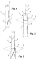
- stator 4 In the drawing the stator of a high-voltage rotating electric machine is denoted 4 and is represented by a square in dashed and dotted lines.
- the stator 4 has several stator teeth extending in parallel and surrounding a rotor (not shown) of the electric machine.
- a duct 2 In the tooth 3 and extending in a straight line from the shown upper end of the tooth 3 to a lower not shown end thereof is a duct 2 having a circular cross section.
- the tube 1 is made of a polymer material and normally runs in loops between the teeth 3 of the stator 4 and is connected to a cooling device (not shown). In the drawing, however, the tube 1 has been cut close to both the upper and lower ends of the stator tooth 3. The reason for that is that the tube 1 is to be dismantled due to a failure, such as a leak.
- a cutting tool 5 For the dismantling a cutting tool 5 according to the invention is used.
- the cutting tool 5 is shown in detail in fig. 1 and in use in fig. 2. It has an elongate body 10 with a circular cylindrical shape, an insertion or top end 13, and an open bottom end 12. The top end 13 is closed, a lug 14 being mounted thereon to be connected to a pull rope 15 (cf. fig. 2).
- the pull rope 15 is used to pull the tool through the tube 1 in a way described further down along a pulling direction (arrow a ).
- a cutting edge 6 protrudes from the cylindrical tool wall.
- the cutting edge 6 forms part of a plane-like structure including a shavings evacuation aperture 11 in said tool wall.
- the cutting edge 6 is not horizontal but inclined somewhat in order to impart the tool 5 a rotating movement when pulled through the tube 1. While being pulled through the tube 1 the cutting edge 6 carves a helical trench into the inner tube wall, the carved away shavings, schematically indicated by an arrow 16 in fig. 1, being led through the aperture 11 and leaving the tool 5 through its open bottom end 12.
- a rod 9 (cf. fig. 3) is inserted into the tube 1.
- the rod 9 is circular cylindrical and has a diameter inferior to the inner diameter of the tube 1.
- the rod 9 has at least one fastening means for attaching an end part of the cut tube 1 thereto.
- the fastening means is a screw 8 which extends through said end part and is tightly secured to the rod 9.
- the cut tube 1 When turning the rod 9 the cut tube 1 reduces its diameter by breaking along said trench or slit 7 as indicated in fig. 3. By reducing the tube diameter starting from the point of attachment to the rod 9 the tube 1 is gradually peeled off the inner wall of the duct 2. The peeled off and helically split tube is easy to pull out of the duct either gradually by turning and pulling the rod 9 at one time as indicated by the arrow b in fig. 3 or by pulling the rod 9 afterwards.
- one way of modifying the method is not to use a rod 9 but to use e.g. a plier to pull the slit tube out, and one way of modifying the tool 5 is to change the shape of the cutting edge 6, e.g. into a knife-edge extending substantially in parallel with the pulling direction a .
Landscapes
- Engineering & Computer Science (AREA)
- Manufacturing & Machinery (AREA)
- Power Engineering (AREA)
- Manufacture Of Motors, Generators (AREA)
- Automatic Assembly (AREA)
- Motor Or Generator Cooling System (AREA)
Applications Claiming Priority (2)
| Application Number | Priority Date | Filing Date | Title |
|---|---|---|---|
| SE0202488A SE0202488D0 (sv) | 2002-08-22 | 2002-08-22 | Method of dismantling a cooling tube in a stator tooth and tool used therefor |
| SE0202488 | 2002-08-22 |
Publications (1)
| Publication Number | Publication Date |
|---|---|
| EP1391978A1 true EP1391978A1 (de) | 2004-02-25 |
Family
ID=20288771
Family Applications (1)
| Application Number | Title | Priority Date | Filing Date |
|---|---|---|---|
| EP03405572A Withdrawn EP1391978A1 (de) | 2002-08-22 | 2003-07-31 | Verfahren zur Demontage eines Kühlungsrohres in einem Statorzahn und Werkzeug hierfür |
Country Status (4)
| Country | Link |
|---|---|
| US (1) | US20040034989A1 (de) |
| EP (1) | EP1391978A1 (de) |
| CA (1) | CA2437723A1 (de) |
| SE (1) | SE0202488D0 (de) |
Families Citing this family (1)
| Publication number | Priority date | Publication date | Assignee | Title |
|---|---|---|---|---|
| EP3197028B1 (de) * | 2016-01-22 | 2018-11-21 | General Electric Technology GmbH | Stromschienenabmantelungswerkzeug |
Citations (5)
| Publication number | Priority date | Publication date | Assignee | Title |
|---|---|---|---|---|
| DE1125067B (de) * | 1960-10-25 | 1962-03-08 | Huettenwerk Oberhausen A G | Verfahren und Vorrichtung zum Entfernen von Nutenisolationsmaterial |
| US3963366A (en) * | 1973-10-29 | 1976-06-15 | Komet Stahlhalter-Und Werkzeugfabrik, Robert Breuning Gmbh | Boring tool for working bores of small diameter |
| US5098232A (en) * | 1983-10-14 | 1992-03-24 | Stellram Limited | Thread cutting tool |
| WO1997045914A1 (en) * | 1996-05-29 | 1997-12-04 | Asea Brown Boveri Ab | Rotary electric machine with axial cooling |
| US6102105A (en) * | 1997-08-06 | 2000-08-15 | Framatome Technologies, Inc. | Repair of electrical generator stator leaks, cracks and crevices |
Family Cites Families (15)
| Publication number | Priority date | Publication date | Assignee | Title |
|---|---|---|---|---|
| US2304793A (en) * | 1941-06-09 | 1942-12-15 | Calpat Corp | Method of and apparatus for cutting pipe |
| US2411246A (en) * | 1942-12-23 | 1946-11-19 | Griscom Russell Co | Method of removing defective tubes from tube sheets |
| US2427843A (en) * | 1945-03-02 | 1947-09-23 | Horace F Dugger | Boiler tube slitter |
| US2507201A (en) * | 1946-09-17 | 1950-05-09 | Evans Clair Otto | Tool for removing tubes from tube sheets |
| US2817555A (en) * | 1953-03-12 | 1957-12-24 | Wash Overshot And Spear Engine | Method and system of retrieving stuck pipe joints in well bores |
| US2998067A (en) * | 1957-07-22 | 1961-08-29 | Jersey Prod Res Co | Method and apparatus for releasing stuck drill pipe |
| US3176384A (en) * | 1963-09-03 | 1965-04-06 | Nils F Johnson | Pipe removing tool |
| US3729806A (en) * | 1968-09-06 | 1973-05-01 | Carrier Corp | Method for tube removal |
| US4043018A (en) * | 1975-12-18 | 1977-08-23 | Westinghouse Electric Corporation | Method and tool for removing tubes from multi-tube finned heat exchange coil |
| US4646413A (en) * | 1985-06-18 | 1987-03-03 | Tri Tool Inc. | Tube extractor drill jig |
| US5023988A (en) * | 1986-10-04 | 1991-06-18 | Lamond Thomas W | Method for removing a bowling ball fingertip insert from a bowling ball finger hole |
| US5893209A (en) * | 1997-09-22 | 1999-04-13 | Weeks; Bruce V. | Apparatus for effecting boiler tube removal |
| US6599067B2 (en) * | 2001-03-26 | 2003-07-29 | Atomic Energy Of Canada Limited | Apparatus for removing pressure tubes |
| US7093360B1 (en) * | 2004-04-06 | 2006-08-22 | Craig Merrill C | Method of removing boiler tubes |
| US7784163B2 (en) * | 2005-03-22 | 2010-08-31 | The Boeing Company | Riveted fastener extraction apparatuses and method |
-
2002
- 2002-08-22 SE SE0202488A patent/SE0202488D0/xx unknown
-
2003
- 2003-07-31 EP EP03405572A patent/EP1391978A1/de not_active Withdrawn
- 2003-08-11 US US10/637,570 patent/US20040034989A1/en not_active Abandoned
- 2003-08-20 CA CA002437723A patent/CA2437723A1/en not_active Abandoned
Patent Citations (5)
| Publication number | Priority date | Publication date | Assignee | Title |
|---|---|---|---|---|
| DE1125067B (de) * | 1960-10-25 | 1962-03-08 | Huettenwerk Oberhausen A G | Verfahren und Vorrichtung zum Entfernen von Nutenisolationsmaterial |
| US3963366A (en) * | 1973-10-29 | 1976-06-15 | Komet Stahlhalter-Und Werkzeugfabrik, Robert Breuning Gmbh | Boring tool for working bores of small diameter |
| US5098232A (en) * | 1983-10-14 | 1992-03-24 | Stellram Limited | Thread cutting tool |
| WO1997045914A1 (en) * | 1996-05-29 | 1997-12-04 | Asea Brown Boveri Ab | Rotary electric machine with axial cooling |
| US6102105A (en) * | 1997-08-06 | 2000-08-15 | Framatome Technologies, Inc. | Repair of electrical generator stator leaks, cracks and crevices |
Also Published As
| Publication number | Publication date |
|---|---|
| US20040034989A1 (en) | 2004-02-26 |
| CA2437723A1 (en) | 2004-02-22 |
| SE0202488D0 (sv) | 2002-08-22 |
Similar Documents
| Publication | Publication Date | Title |
|---|---|---|
| US7354228B2 (en) | Drilling tool for insertion of cabling | |
| US12308624B2 (en) | Coupling device and method for pulling an electrical wire through a conduit | |
| EP0206404A1 (de) | Rohrabziehvorrichtung mit Aufspannvorrichtung für Bohrer | |
| EP1391978A1 (de) | Verfahren zur Demontage eines Kühlungsrohres in einem Statorzahn und Werkzeug hierfür | |
| EP1080859A1 (de) | Kernbohrer | |
| JP5688848B2 (ja) | 地盤補強用鋼管及びその製造方法 | |
| JP5064641B2 (ja) | 絶縁エレメント、及び巻き付けエレメントを電機子の溝内に取り付ける方法 | |
| CN109648248B (zh) | 一种蒸汽发生器传热管取管方法 | |
| JP5456347B2 (ja) | 既設配管の抜管装置および既設配管の抜管方法 | |
| KR20100060239A (ko) | 모터의 회전자 인출 장치 | |
| WO2022154854A1 (en) | Embedded wire removal tool | |
| CN210110436U (zh) | 一种剥线机 | |
| KR20200023114A (ko) | 융합형 타이어 수리툴과 이를 이용한 타이어 수리장치 | |
| KR102496587B1 (ko) | 외장관 천공 장치 | |
| EP0048082B1 (de) | Spindel zum Schneiden, Abisolieren und Umwickeln eines isolierten Leiterdrahtes | |
| CA2646448A1 (en) | Method for reducing diameter reduction near ends of expanded tubulars | |
| CN223297182U (zh) | 手电钻bv线头并线工具 | |
| CN208923736U (zh) | 一种线束剪剥机 | |
| JP7810353B2 (ja) | 回収方法、回収装置及びコア回収具 | |
| JP4815137B2 (ja) | 水道配管の穿孔カッター | |
| KR20160146189A (ko) | 파이프의 버 제거 장치 | |
| KR102912864B1 (ko) | 헬리코일 제거기 | |
| JP3174473U (ja) | 箱抜き管取外し器具 | |
| CN116404836A (zh) | 一种电机转子绕线机 | |
| US20010025638A1 (en) | Drill bit |
Legal Events
| Date | Code | Title | Description |
|---|---|---|---|
| PUAI | Public reference made under article 153(3) epc to a published international application that has entered the european phase |
Free format text: ORIGINAL CODE: 0009012 |
|
| AK | Designated contracting states |
Kind code of ref document: A1 Designated state(s): AT BE BG CH CY CZ DE DK EE ES FI FR GB GR HU IE IT LI LU MC NL PT RO SE SI SK TR |
|
| AX | Request for extension of the european patent |
Extension state: AL LT LV MK |
|
| RAP1 | Party data changed (applicant data changed or rights of an application transferred) |
Owner name: ALSTOM TECHNOLOGY LTD |
|
| 17P | Request for examination filed |
Effective date: 20040818 |
|
| AKX | Designation fees paid |
Designated state(s): SE |
|
| REG | Reference to a national code |
Ref country code: DE Ref legal event code: 8566 |
|
| 17Q | First examination report despatched |
Effective date: 20070126 |
|
| STAA | Information on the status of an ep patent application or granted ep patent |
Free format text: STATUS: THE APPLICATION HAS BEEN WITHDRAWN |
|
| 18W | Application withdrawn |
Effective date: 20071114 |