EP1391908B1 - Magnetron für Mikrowellenherde - Google Patents
Magnetron für Mikrowellenherde Download PDFInfo
- Publication number
- EP1391908B1 EP1391908B1 EP02258076A EP02258076A EP1391908B1 EP 1391908 B1 EP1391908 B1 EP 1391908B1 EP 02258076 A EP02258076 A EP 02258076A EP 02258076 A EP02258076 A EP 02258076A EP 1391908 B1 EP1391908 B1 EP 1391908B1
- Authority
- EP
- European Patent Office
- Prior art keywords
- diameter
- small
- magnetron
- vanes
- diameter strip
- Prior art date
- Legal status (The legal status is an assumption and is not a legal conclusion. Google has not performed a legal analysis and makes no representation as to the accuracy of the status listed.)
- Expired - Lifetime
Links
Images


Classifications
-
- H—ELECTRICITY
- H05—ELECTRIC TECHNIQUES NOT OTHERWISE PROVIDED FOR
- H05B—ELECTRIC HEATING; ELECTRIC LIGHT SOURCES NOT OTHERWISE PROVIDED FOR; CIRCUIT ARRANGEMENTS FOR ELECTRIC LIGHT SOURCES, IN GENERAL
- H05B6/00—Heating by electric, magnetic or electromagnetic fields
- H05B6/64—Heating using microwaves
- H05B6/72—Radiators or antennas
-
- H—ELECTRICITY
- H01—ELECTRIC ELEMENTS
- H01J—ELECTRIC DISCHARGE TUBES OR DISCHARGE LAMPS
- H01J23/00—Details of transit-time tubes of the types covered by group H01J25/00
- H01J23/14—Leading-in arrangements; Seals therefor
- H01J23/15—Means for preventing wave energy leakage structurally associated with tube leading-in arrangements, e.g. filters, chokes, attenuating devices
-
- H—ELECTRICITY
- H01—ELECTRIC ELEMENTS
- H01J—ELECTRIC DISCHARGE TUBES OR DISCHARGE LAMPS
- H01J23/00—Details of transit-time tubes of the types covered by group H01J25/00
- H01J23/16—Circuit elements, having distributed capacitance and inductance, structurally associated with the tube and interacting with the discharge
- H01J23/18—Resonators
- H01J23/22—Connections between resonators, e.g. strapping for connecting resonators of a magnetron
-
- H—ELECTRICITY
- H01—ELECTRIC ELEMENTS
- H01J—ELECTRIC DISCHARGE TUBES OR DISCHARGE LAMPS
- H01J25/00—Transit-time tubes, e.g. klystrons, travelling-wave tubes, magnetrons
- H01J25/50—Magnetrons, i.e. tubes with a magnet system producing an H-field crossing the E-field
- H01J25/52—Magnetrons, i.e. tubes with a magnet system producing an H-field crossing the E-field with an electron space having a shape that does not prevent any electron from moving completely around the cathode or guide electrode
- H01J25/58—Magnetrons, i.e. tubes with a magnet system producing an H-field crossing the E-field with an electron space having a shape that does not prevent any electron from moving completely around the cathode or guide electrode having a number of resonators; having a composite resonator, e.g. a helix
- H01J25/587—Multi-cavity magnetrons
Definitions
- the present invention relates to a magnetron, and more particularly to a magnetron suitable for use in a microwave oven.
- a magnetron includes an anode, and a cathode which discharges thermions.
- the thermions are spirally moved by an electromagnetic force to reach the anode.
- a spinning electron pole is generated around the cathode by the thermions and an induced current is generated in an oscillation circuit of the anode, so as to continuously stimulate an oscillation.
- the oscillation frequency of the magnetron is generally determined by the oscillation circuit, and has high efficiency and high output power.
- the above-described magnetron is widely used as parts of home appliances, including a microwave oven, as well as parts of industrial applications, such as a high-frequency heating apparatus, a particle accelerator and a radar system.
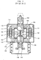
- Figures 1 to 3 show the construction of a conventional magnetron.
- the magnetron includes a positive polar cylinder 101 made of, for example, an oxygen free copper pipe, and a plurality of vanes 102 which are disposed in the positive polar cylinder 101 and constitute a positive polar section along with the positive polar cylinder 101.
- the vanes 102 are radially arranged at regular intervals to form a cavity resonator.
- An antenna 103 is connected to one of the vanes 102 to induce harmonics to the outside.
- a large-diameter strip ring 104 and a small-diameter strip ring 105 are disposed on upper and lower portions of the vanes 102, respectively, to alternately and electrically connect the vanes 102 so that the vanes 102 alternately have the same electric potential.
- Rectangular vane channels 202 are formed in the vanes 102, respectively, to allow the strip rings 104 and 105 to alternately and electrically connect the vanes 102, and cause each opposite pair of vanes 102 to be disposed in an upside-down manner.
- each opposite pair of vanes 102 and the positive polar cylinder 101 constitute a certain inductive-capacitive (LC) resonant circuit.
- a filament 106 in a form of a coil spring is disposed in an axial center portion of the positive polar cylinder 101, and an activating space 107 is provided between radial inside ends of the vanes 102 and the filament 106.
- a top shield 108 and a bottom shield 109 are attached to a top and bottom of the filament 106, respectively.
- a center lead 110 is fixedly welded to a bottom of the top shield 108 while passing through a through hole of the bottom shield 109 and the filament 106.
- a side lead 111 is welded to a bottom of the bottom shield 109. The center lead 110 and the side lead 111 are connected to terminals of an external power source (not shown), so as to form a closed circuit in the magnetron.
- An upper permanent magnet 112 and a lower permanent magnet 113 are provided to apply a magnetic field to the activating space 107 with the opposite magnetic poles of the upper and lower permanent magnets 112 and 113 facing each other.
- An upper pole piece 117 and a lower pole piece 118 are provided to induce rotating magnetic flux generated by the permanent magnets 112 and 113 into the activating space 107.
- a reference numeral 116 designates cooling fins which connect the positive polar cylinder 101 to the lower yoke 115 and radiate heat generated in the positive polar cylinder 101 to the outside through the lower yoke 115.
- the filament 106 is heated by an operational current supplied to the filament 106, and thermions are emitted from the filament 106.
- a thermion group 301 is produced in the activating space 107 by the emitted thermions.
- the thermion group 301 alternately imparts a potential difference to each neighboring pair of vanes 102 while being in contact with front ends of the vanes 102, being rotated by the influence of a magnetic field formed in the activating space 107 and being moved from one state "i" to the other state "f.” Accordingly, harmonics corresponding to a rotation speed of the thermion group 301 are generated by the oscillation of the LC resonant circuit formed by the vanes 102 and the positive polar cylinder 101, and are transmitted to the outside through the antenna 103.
- the values of the variables of the equation are determined by the geometrical configurations of circuit elements. Accordingly, the configurations of the vanes 102 constituting a part of the LC resonant circuit are principal factors that determine the frequency of the harmonics.
- An oscillation frequency of a magnetron for microwave ovens is fixed to a frequency of 2,450 MHz. Since the magnetron for the microwave ovens has a fixed frequency, the magnetron has to be precisely adjusted to the frequency of 2,450 MHz during a production thereof. Although the magnetron has a fixed frequency, the oscillation frequency of the magnetron varies in a range from about ⁇ 10 to about ⁇ 15 MHz around a central frequency by the variation of a load under actual operational conditions.
- the magnetron generates a variety of frequencies, a single prominent frequency is specified by a frequency measuring process, and referred to as the oscillation frequency of the magnetron.
- the large-diameter strip ring 104 and the small-diameter strip ring 105, as well as the vanes 102 play principal roles. That is, electric phases of the large-diameter and small-diameter strip rings 104 and 105, which alternately connect the alternately arranged vanes 102 to allow each set of vanes 102 to have the same potential, are changed as electric phases of the vanes 102 are changed.
- the large- and small-diameter strip rings 104 and 105 oscillate while experiencing the alternate change of the electric phases.
- a certain amount of electrostatic capacity exists between the large-diameter and small-diameter strip rings 104 and 105 facing each other, and a certain electric oscillation is generated therebetween, generating an unwanted frequency called a parasitic frequency.
- a minute frequency is set using the large-and small-diameter strip rings 104 and 105.
- the shapes and sizes of the large- and small-diameter strip rings 104 and 105 which are fixedly mounted in the magnetron, determine an electrostatic capacity between the large-diameter and small-diameter strip rings 104 and 105, and a frequency related to the electrostatic capacity is generated.
- the magnetron is designed to adjust its frequency by controlling the shapes and sizes of the large-diameter and small-diameter strip rings 104 and 105, and is required to have an entirely symmetrical configuration.
- the change of the frequency of the magnetron changes a Q value that determines the efficiency of the magnetron, and accordingly, changes the efficiency of the magnetron.
- the large-diameter strip ring 104 has a geometrical configuration of an inside diameter of 17.2 mm, an outside diameter of 18.6 mm, a thickness of 0.7 mm and a height of 1.5 mm
- the small-diameter strip ring 105 has a geometrical configuration of an inside diameter of 13.9 mm, an outside diameter of 15.35 mm, a thickness of 0.725 mm and a height of 1.5 mm.
- a Q value that determines the efficiency of the magnetron having such geometric configurations is about 1,850. In the past, many attempts have been made to increase the Q value without success while maintaining the oscillation frequency of the magnetron at 2450 MHz.
- a preferred aim is to provide the large and small-diameter strip rings to change a frequency generated in the magnetron and increase a Q value so as to improve the quality of the frequency and the efficiency of the magnetron.
- a magnetron comprising: a positive polar section including a positive polar cylinder and a plurality of vanes; and a large-diameter strip ring and a small-diameter strip ring which are disposed on an upper portion and a lower portion of the vanes, respectively, and alternatively and electrically connect the vanes to one another, wherein: the large-diameter strip ring has inside and outside diameters which are in the range of 17.1 mm to 18.01 mm and 18.6 mm to 19.6 mm, respectively, the small-diameter strip ring has inside and outside diameters which are in the range of 13.4 mm to 14.4 mm and 14.9 mm to 15.9 mm, respectively, and the large-diameter and small-diameter strip rings have a height which is in the range of 1.55 mm to 1.65 mm.
- the large-diameter and small-diameter strip rings have substantially the same height, or substantially the same thicknesses, and preferably both height and thickness are equal.
- the inside and outside diameters of the large-diameter strip ring are 17.6 mm and 19.1 mm, respectively, the inside and outside diameters of the small-diameter strip ring are 13.9 mm and 15.4 mm, respectively, and the height of the large-diameter and small-diameter strip rings is 1.55 mm.
- the inside diameter of the large-diameter strip ring and the outside diameter of the small-diameter strip ring have a difference which is maintained in an error range of 2.20 mm.
- the vanes are arranged at regular intervals so as to form a cavity resonator, and each opposite pair of the vanes and the positive polar cylinder constitute an inductive-capacitive resonant circuit.
- the large-diameter and small-diameter strip rings alternately and electrically connect the vanes to one another so as to have the vanes alternately have the same electrical potential.
- the magnetron has an unloaded Q value of about 2,000.
- the present invention also extends to a magnetron adapted for use in a microwave oven, and to a microwave oven comprising the magnetron defined herein.
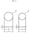
- Figure 4 shows a large-diameter strip ring 401 and a small-diameter strip ring 402 for use in, for example, a magnetron of microwave ovens according to an embodiment of the present invention.
- a reference character “a” designates the difference between upper and lower ends of the large-diameter strip ring 401, that is, a height of the large-diameter strip ring 401.
- a reference character “b” designates an inside diameter of the large-diameter strip ring 401, and a reference character “c” designates an outside diameter of the large-diameter strip ring 401.
- the difference between the inside and outside diameters "b” and "c" of the large-diameter strip ring 401 refers to a thickness of the large-diameter strip ring 401.
- a reference character "d” designates a height of the small-diameter strip ring 402
- a reference character “e” designates an inside diameter of the small-diameter strip ring 402
- a reference character “f” designates an outside diameter of the small-diameter strip ring 402
- the difference between the inside and outside diameters "e” and "f" of the small-diameter strip ring 402 designates a thickness of the small-diameter strip ring 402.
- the difference between the inside diameter of the large-diameter and strip ring 401 and the outside diameter of the small-diameter strip ring 402 is 2.20 mm.
- a resonant frequency of a microwave generated in a positive polar cylinder significantly depends on the configuration of vanes and the configuration of the large-diameter and small-diameter strip rings 401 and 402. That is, the above-described structural configurations of a magnetron are principal factors that determine a resonant frequency of the magnetron.
- a frequency of a resonator is related to an electrostatic capacity
- the value of the electrostatic capacity is a constant value that is determined in relation only to geometrical configurations, such as a distance between and sizes of both conductors constituting a capacitor.
- electrostatic capacities on the large-diameter strip ring 401 and the small-diameter strip ring 402 are proportional to a total Q-factor value, and the Q-factor is proportional to an efficiency, thus resulting in an increase in the efficiency of the magnetron.
- the electrostatic capacities are constant values that are determined by the geometrical configurations of the large-diameter and small-diameter strip rings 401 and 402. Accordingly, these geometrical configurations are principal factors that determine the efficiency of the magnetron.
- an electrostatic capacity between the large-diameter and small-diameter strip rings 401 and 402, which is related to the unloaded Q value, is determined by the geometrical configurations of the large-diameter and small-diameter strip rings 401 and 402, such as sizes of the opposite surfaces of the large-diameter and small-diameter strip rings 401 and 402.
- a magnetron can be constructed to have an unloaded Q value of about 2,000 by not taking an exact value of 0.75 mm, but a value in the range of error and changing other factors, such as a height, and an inside diameter or an outside diameter of the large-diameter and small-diameter strip rings 401 and 402, so as to change the sizes of the opposite surfaces of the large-diameter and small-diameter strip rings 401 and 402.
- the large-diameter and small-diameter strip rings 401 and 402 it is appropriate to construct the large-diameter and small-diameter strip rings 401 and 402 to allow a difference between the inside diameter and outside diameter respectively therebetween, which determines Qs and Cs, to be 2.20 mm as described in the above-described embodiment.
- the geometrical configurations of the large-diameter and small-diameter strip rings 401 and 402 have a different range of numerical values in the case where the difference between the inside diameter of the large-diameter strip rings 401 and the outside diameter of the small-diameter strip ring 402 does not reach 2.20 mm within the range of an allowable error.
- large-diameter and small-diameter strip rings are constructed to merely allow their heights to be the same so as to maintain the efficiency of a conventional magnetron
- large-diameter and small-diameter strip rings of the present invention are constructed to allow their heights and thicknesses to be the same, respectively, so the large-diameter and small-diameter strip rings of the present invention can have the above-described numerical values to improve the Q value of the magnetron to a value of 2,000.
- the present invention provides a magnetron for use in, for example, microwave ovens, which incorporates therein a large-diameter strip ring and a small-diameter strip ring having improved geometrical configurations.
- the improved geometrical configurations reduce noise of a frequency generated in the magnetron, and improve the efficiency and the reliability of the magnetron.
Landscapes
- Physics & Mathematics (AREA)
- Electromagnetism (AREA)
- Microwave Tubes (AREA)
Claims (11)
- Magnetron mit:einem positiven Polarabschnitt, einschließlich einem positiven Polarzylinder undeiner Mehrzahl an Flügeln (102); undeinem Streifring mit großem Durchmesser (401) und einem Streifring mit kleinem Durchmesser (402), die an einem oberen bzw. einem unteren Bereich der Flügel (102) angeordnet sind und die Flügeln (102) abwechselnd und elektrisch miteinander verbinden;dadurch gekennzeichnet, dassder Streifring mit großem Durchmesser (401) Innen- und Außendurchmesser aufweist, die im Bereich von 17,1 mm bis 18,01 mm bzw. 18,6 mm bis 19,6 mm liegen, wobei der Streifring mit kleinem Durchmesser (402) Innen- und Außendurchmesser aufweist, die im Bereich von 13,4 mm bis 14,4 mm bzw. 14,9 mm bis 15,9 mm liegen, und die Streifringe mit großem Durchmesser und kleinem Durchmesser (401, 402) eine Höhe aufweisen, die im Bereich von 1,55 mm bis 1,65 mm liegt.
- Magnetron nach Anspruch 1, wobei die Streifringe mit großem Durchmesser und kleinem Durchmesser (401, 402) im Wesentlichen die gleiche Höhe aufweisen.
- Magnetron nach Anspruch 1 oder 2, wobei die Streifringe mit großem Durchmesser und kleinem Durchmesser (401, 402) im Wesentlichen die gleiche Dicke aufweisen.
- Magnetron nach Anspruch 3, wobei die Dicke zwischen dem Innen- und Außendurchmesser des Streifrings mit großem Durchmesser (401) im Wesentlichen gleich der Dicke zwischen dem Innen- und Außendurchmesser des Streifrings mit kleinem Durchmesser (402) ist.
- Magnetron nach einem der vorangehenden Ansprüche, wobei:die Innen- und Außendurchmesser des Streifrings mit großem Durchmesser (401) 17,6 mm bzw. 19,1 mm betragen, und die Innen- und Außendurchmesser des Streifrings mit kleinem Durchmesser (402) 13,9 mm bzw. 15,4 mm betragen, und die Höhe der Streifringe mit großem Durchmesser und kleinem Durchmesser (401, 402) 1,55 mm beträgt.
- Magnetron nach einem der vorangehenden Ansprüche, wobei der Innendurchmesser des Streifrings mit großem Durchmesser (401) und der Außendurchmesser des Streifrings mit kleinem Durchmesser (402) eine Differenz von 2,20 mm aufweist.
- Magnetron nach einem der vorangehenden Ansprüche, wobei die Flügel (102) in regelmäßigen Intervallen angeordnet sind, um einen Hohlraumresonator zu bilden, und jedes gegenüberliegende Paar von Flügeln (102) und der positive Polarzylinder (101) eine induktive-kapazitive Resonanzschaltung bilden.
- Magnetron nach einem der vorangehenden Ansprüche, wobei die Streifringe mit großem Durchmesser und kleinem Durchmesser (401, 402) die Flügel (102) abwechselnd und elektrisch miteinander verbinden, so dass die Flügel (102) abwechselnd das gleiche elektrische Potential aufweisen.
- Magnetron nach einem der vorangehenden Ansprüche, des Weiteren mit:einer Antenne (103), die mit einem der Flügel (102) verbunden ist und harmonische Schwingungen von dem positiven Polarzylinder (101) nach außen induziert;einem Glühdraht (106), der in einem axialen mittleren Bereich des positiven Polarzylinders angeordnet ist, wobei ein Aktivierungsraum zwischen radialen Innenenden der Flügel (102) und dem Glühdraht vorgesehen ist;oberen und unteren Abschirmungen (108, 109), die an jeweiligen Endbereichen des Glühdrahts befestigt sind;einer zentralen Leitung (110), die an dem Boden der oberen Abschirmung angebracht ist und durch ein Durchgangsloch der Bodenabschirmung und den Glühdraht durchtritt;einer seitlichen Leitung (111), die am Boden der Bodenabschirmung angebracht ist;oberen und unteren Magneten (112, 113), die ein Magnetfeld auf den Aktivierungsraum ausüben, wobei gegenüber liegende Magnetpole des oberen und unteren Magneten einander zugewandt sind;oberen und unteren Poleinheiten (117, 118), die einen durch den oberen und unteren Magneten erzeugten rotierenden Magnetfluss in den Aktivierungsraum induzieren;oberen und unteren Jochs (114, 115), die an jeweiligen Endbereichen des positiven Polarzylinders vorgesehen sind; undKühlrippen (116), die den positiven Polarzylinder mit dem unteren Joch verbinden und im positiven Polarzylinder erzeugte Wärme von dem positiven Polarzylinder nach außen abstrahlen.
- Magnetron nach einem der vorangehenden Ansprüche, wobei das Magnetron einen unbelasteten Q-Wert von 2000 aufweist.
- Mikrowellenherd, mit einem Magnetron nach einem der vorangehenden Ansprüche.
Applications Claiming Priority (2)
| Application Number | Priority Date | Filing Date | Title |
|---|---|---|---|
| KR2002044453 | 2002-07-27 | ||
| KR1020020044453A KR20040011638A (ko) | 2002-07-27 | 2002-07-27 | 마그네트론 |
Publications (3)
| Publication Number | Publication Date |
|---|---|
| EP1391908A2 EP1391908A2 (de) | 2004-02-25 |
| EP1391908A3 EP1391908A3 (de) | 2007-08-22 |
| EP1391908B1 true EP1391908B1 (de) | 2008-07-23 |
Family
ID=30439400
Family Applications (1)
| Application Number | Title | Priority Date | Filing Date |
|---|---|---|---|
| EP02258076A Expired - Lifetime EP1391908B1 (de) | 2002-07-27 | 2002-11-25 | Magnetron für Mikrowellenherde |
Country Status (6)
| Country | Link |
|---|---|
| US (1) | US6759639B2 (de) |
| EP (1) | EP1391908B1 (de) |
| JP (1) | JP2004063441A (de) |
| KR (1) | KR20040011638A (de) |
| CN (1) | CN1471125A (de) |
| DE (1) | DE60227800D1 (de) |
Families Citing this family (3)
| Publication number | Priority date | Publication date | Assignee | Title |
|---|---|---|---|---|
| CN100493271C (zh) * | 2002-08-02 | 2009-05-27 | 夏普株式会社 | 高频加热装置 |
| JP2005259508A (ja) * | 2004-03-11 | 2005-09-22 | Toshiba Hokuto Electronics Corp | 電子レンジ用マグネトロン |
| JP5676899B2 (ja) * | 2010-03-25 | 2015-02-25 | 東芝ホクト電子株式会社 | マグネトロンおよびこれを用いた電子レンジ |
Family Cites Families (9)
| Publication number | Priority date | Publication date | Assignee | Title |
|---|---|---|---|---|
| JPS56149750A (en) * | 1980-04-23 | 1981-11-19 | Nec Home Electronics Ltd | Magnetron |
| JPS61281435A (ja) * | 1985-05-02 | 1986-12-11 | Sanyo Electric Co Ltd | マグネトロン |
| JPH0230036A (ja) * | 1988-02-03 | 1990-01-31 | Sanyo Electric Co Ltd | マグネトロン |
| KR920003337B1 (ko) * | 1990-05-31 | 1992-04-27 | 주식회사 금성사 | 마그네트론의 양극조립기체의 제조방법 |
| JPH056738A (ja) * | 1991-06-27 | 1993-01-14 | Hitachi Ltd | マグネトロン |
| JPH0652805A (ja) * | 1992-07-28 | 1994-02-25 | Hitachi Ltd | マグネトロン |
| JP3278464B2 (ja) * | 1992-09-04 | 2002-04-30 | 株式会社東芝 | 電子レンジ用マグネトロン |
| KR100323704B1 (ko) * | 1999-11-03 | 2002-02-07 | 구자홍 | 마그네트론 |
| JP4670027B2 (ja) * | 2000-10-18 | 2011-04-13 | 日立協和エンジニアリング株式会社 | マグネトロン |
-
2002
- 2002-07-27 KR KR1020020044453A patent/KR20040011638A/ko not_active Ceased
- 2002-11-13 CN CNA021505446A patent/CN1471125A/zh active Pending
- 2002-11-25 DE DE60227800T patent/DE60227800D1/de not_active Expired - Lifetime
- 2002-11-25 EP EP02258076A patent/EP1391908B1/de not_active Expired - Lifetime
- 2002-11-25 US US10/303,009 patent/US6759639B2/en not_active Expired - Fee Related
- 2002-12-06 JP JP2002355833A patent/JP2004063441A/ja active Pending
Also Published As
| Publication number | Publication date |
|---|---|
| CN1471125A (zh) | 2004-01-28 |
| KR20040011638A (ko) | 2004-02-11 |
| JP2004063441A (ja) | 2004-02-26 |
| US6759639B2 (en) | 2004-07-06 |
| EP1391908A2 (de) | 2004-02-25 |
| US20040016753A1 (en) | 2004-01-29 |
| DE60227800D1 (de) | 2008-09-04 |
| EP1391908A3 (de) | 2007-08-22 |
Similar Documents
| Publication | Publication Date | Title |
|---|---|---|
| EP1870923B1 (de) | Magnetron | |
| EP1422738A2 (de) | Magnetron für einen Mikrowellenofen | |
| EP0769797B1 (de) | Magnetron | |
| EP1316984B1 (de) | Magnetrongerät | |
| US4310786A (en) | Magnetron tube with improved low cost structure | |
| EP1391908B1 (de) | Magnetron für Mikrowellenherde | |
| EP1403899A2 (de) | Magnetron für Mikrowellenherde | |
| JP4038883B2 (ja) | 高周波型加速管 | |
| KR20060043802A (ko) | 전자 레인지용 마그네트론 | |
| US9852872B2 (en) | Magnetron | |
| EP1482531B1 (de) | Magnetron | |
| EP1403900A2 (de) | Magnetron eines Mikrowellenofens | |
| EP1388879A2 (de) | Magnetron | |
| EP1388880A2 (de) | Magnetron für Mikrowellenöfen | |
| KR100266604B1 (ko) | 마그네트론의 고주파 누설 방지구조 | |
| KR100275970B1 (ko) | 마이크로스트립을 이용한 입력부 필터를 가지는 마그네트론 | |
| KR100285855B1 (ko) | 곡면형 베인 구조를 가진 마그네트론 | |
| KR200152144Y1 (ko) | 마그네트론의 라인쵸크구조 | |
| KR20030089308A (ko) | 마그네트론의 입력부 차폐구조 | |
| EP0209219A1 (de) | Koaxialmagnetrons | |
| JP2003331744A (ja) | マグネトロン | |
| JPH0652805A (ja) | マグネトロン | |
| KR20040061411A (ko) | 마그네트론의 안테나 캡 설치구조 | |
| KR20010068384A (ko) | 마그네트론 | |
| KR20030089322A (ko) | 마그네트론의 요크구조 |
Legal Events
| Date | Code | Title | Description |
|---|---|---|---|
| PUAI | Public reference made under article 153(3) epc to a published international application that has entered the european phase |
Free format text: ORIGINAL CODE: 0009012 |
|
| 17P | Request for examination filed |
Effective date: 20021217 |
|
| AK | Designated contracting states |
Kind code of ref document: A2 Designated state(s): AT BE BG CH CY CZ DE DK EE ES FI FR GB GR IE IT LI LU MC NL PT SE SK TR |
|
| AX | Request for extension of the european patent |
Extension state: AL LT LV MK RO SI |
|
| PUAL | Search report despatched |
Free format text: ORIGINAL CODE: 0009013 |
|
| AK | Designated contracting states |
Kind code of ref document: A3 Designated state(s): AT BE BG CH CY CZ DE DK EE ES FI FR GB GR IE IT LI LU MC NL PT SE SK TR |
|
| AX | Request for extension of the european patent |
Extension state: AL LT LV MK RO SI |
|
| 17Q | First examination report despatched |
Effective date: 20071023 |
|
| GRAP | Despatch of communication of intention to grant a patent |
Free format text: ORIGINAL CODE: EPIDOSNIGR1 |
|
| AKX | Designation fees paid |
Designated state(s): DE FR GB |
|
| GRAS | Grant fee paid |
Free format text: ORIGINAL CODE: EPIDOSNIGR3 |
|
| GRAA | (expected) grant |
Free format text: ORIGINAL CODE: 0009210 |
|
| AK | Designated contracting states |
Kind code of ref document: B1 Designated state(s): DE FR GB |
|
| REG | Reference to a national code |
Ref country code: GB Ref legal event code: FG4D |
|
| REF | Corresponds to: |
Ref document number: 60227800 Country of ref document: DE Date of ref document: 20080904 Kind code of ref document: P |
|
| PLBE | No opposition filed within time limit |
Free format text: ORIGINAL CODE: 0009261 |
|
| STAA | Information on the status of an ep patent application or granted ep patent |
Free format text: STATUS: NO OPPOSITION FILED WITHIN TIME LIMIT |
|
| 26N | No opposition filed |
Effective date: 20090424 |
|
| PGFP | Annual fee paid to national office [announced via postgrant information from national office to epo] |
Ref country code: DE Payment date: 20131113 Year of fee payment: 12 |
|
| PGFP | Annual fee paid to national office [announced via postgrant information from national office to epo] |
Ref country code: FR Payment date: 20141023 Year of fee payment: 13 Ref country code: GB Payment date: 20141021 Year of fee payment: 13 |
|
| REG | Reference to a national code |
Ref country code: DE Ref legal event code: R119 Ref document number: 60227800 Country of ref document: DE |
|
| PG25 | Lapsed in a contracting state [announced via postgrant information from national office to epo] |
Ref country code: DE Free format text: LAPSE BECAUSE OF NON-PAYMENT OF DUE FEES Effective date: 20150602 |
|
| GBPC | Gb: european patent ceased through non-payment of renewal fee |
Effective date: 20151125 |
|
| REG | Reference to a national code |
Ref country code: FR Ref legal event code: ST Effective date: 20160729 |
|
| PG25 | Lapsed in a contracting state [announced via postgrant information from national office to epo] |
Ref country code: GB Free format text: LAPSE BECAUSE OF NON-PAYMENT OF DUE FEES Effective date: 20151125 |
|
| PG25 | Lapsed in a contracting state [announced via postgrant information from national office to epo] |
Ref country code: FR Free format text: LAPSE BECAUSE OF NON-PAYMENT OF DUE FEES Effective date: 20151130 |