EP1391618B1 - Schraubensicherung - Google Patents
Schraubensicherung Download PDFInfo
- Publication number
- EP1391618B1 EP1391618B1 EP20030018823 EP03018823A EP1391618B1 EP 1391618 B1 EP1391618 B1 EP 1391618B1 EP 20030018823 EP20030018823 EP 20030018823 EP 03018823 A EP03018823 A EP 03018823A EP 1391618 B1 EP1391618 B1 EP 1391618B1
- Authority
- EP
- European Patent Office
- Prior art keywords
- screw
- thread
- external
- flank
- threads
- Prior art date
- Legal status (The legal status is an assumption and is not a legal conclusion. Google has not performed a legal analysis and makes no representation as to the accuracy of the status listed.)
- Expired - Lifetime
Links
- 239000011295 pitch Substances 0.000 claims 5
- 239000000853 adhesive Substances 0.000 description 8
- 230000001070 adhesive effect Effects 0.000 description 8
- 230000006835 compression Effects 0.000 description 8
- 238000007906 compression Methods 0.000 description 8
- 238000013016 damping Methods 0.000 description 8
- 238000003825 pressing Methods 0.000 description 6
- 230000007797 corrosion Effects 0.000 description 4
- 238000005260 corrosion Methods 0.000 description 4
- 230000000694 effects Effects 0.000 description 4
- 239000012207 thread-locking agent Substances 0.000 description 4
- 230000006378 damage Effects 0.000 description 3
- 230000001419 dependent effect Effects 0.000 description 3
- 239000012530 fluid Substances 0.000 description 3
- 238000009434 installation Methods 0.000 description 3
- 239000000463 material Substances 0.000 description 3
- 239000004033 plastic Substances 0.000 description 3
- 238000002788 crimping Methods 0.000 description 2
- 230000005923 long-lasting effect Effects 0.000 description 2
- 238000004519 manufacturing process Methods 0.000 description 2
- 230000002093 peripheral effect Effects 0.000 description 2
- 238000007789 sealing Methods 0.000 description 2
- 239000004952 Polyamide Substances 0.000 description 1
- 229910000831 Steel Inorganic materials 0.000 description 1
- 238000013459 approach Methods 0.000 description 1
- 239000002775 capsule Substances 0.000 description 1
- 238000010276 construction Methods 0.000 description 1
- 230000003247 decreasing effect Effects 0.000 description 1
- 230000002349 favourable effect Effects 0.000 description 1
- 230000010006 flight Effects 0.000 description 1
- 230000001939 inductive effect Effects 0.000 description 1
- 230000002401 inhibitory effect Effects 0.000 description 1
- 238000003780 insertion Methods 0.000 description 1
- 230000037431 insertion Effects 0.000 description 1
- 238000007689 inspection Methods 0.000 description 1
- 230000002427 irreversible effect Effects 0.000 description 1
- 230000033001 locomotion Effects 0.000 description 1
- 238000000034 method Methods 0.000 description 1
- 229920002647 polyamide Polymers 0.000 description 1
- 230000002829 reductive effect Effects 0.000 description 1
- 230000002441 reversible effect Effects 0.000 description 1
- 239000007787 solid Substances 0.000 description 1
- 239000010959 steel Substances 0.000 description 1
- 238000012360 testing method Methods 0.000 description 1
- XLYOFNOQVPJJNP-UHFFFAOYSA-N water Substances O XLYOFNOQVPJJNP-UHFFFAOYSA-N 0.000 description 1
Images

Classifications
-
- F—MECHANICAL ENGINEERING; LIGHTING; HEATING; WEAPONS; BLASTING
- F16—ENGINEERING ELEMENTS AND UNITS; GENERAL MEASURES FOR PRODUCING AND MAINTAINING EFFECTIVE FUNCTIONING OF MACHINES OR INSTALLATIONS; THERMAL INSULATION IN GENERAL
- F16B—DEVICES FOR FASTENING OR SECURING CONSTRUCTIONAL ELEMENTS OR MACHINE PARTS TOGETHER, e.g. NAILS, BOLTS, CIRCLIPS, CLAMPS, CLIPS OR WEDGES; JOINTS OR JOINTING
- F16B39/00—Locking of screws, bolts or nuts
- F16B39/22—Locking of screws, bolts or nuts in which the locking takes place during screwing down or tightening
- F16B39/28—Locking of screws, bolts or nuts in which the locking takes place during screwing down or tightening by special members on, or shape of, the nut or bolt
- F16B39/30—Locking exclusively by special shape of the screw-thread
Definitions
- the invention relates to a screw lock, in particular for use in housing parts of valves, in particular proportional valves, with the features of claim 1.
- the respective screw locks are in a variety of embodiments freely available on the market.
- the frictional engagement is dependent on the diameter and thread projection of the required securing and test torque generated related security elements.
- the solid connection the external thread for example in the form of a screw bolt
- With the fuse element close forget the fuse as is the case with loose discs, spring washers, etc.
- threadlockers are known by means of an adhesive that is curable at room temperature and the on the threads, for example in the form of an external thread on a Screw is applied.
- the Adhesive in microencapsulated form and after application on the screw threads, the adhesive remains inactive until through the Screw in the counter thread (internal thread) to burst the capsules and cause the adhesive to cure. After complete curing is the adhesive not only a reliable screw locking, but also allows a seal against the screw connection Fluids such as oil, water, gasoline etc.
- a disadvantage of the known solution is that the curing of the adhesive after screwing is temperature dependent and sometimes several Hours hardening time at room temperature and elevated temperatures needed to ensure a secure action of the screw lock too reach. Also, the life of known fuses is over the adhesive for about 4 years under normal dry conditions indicated so that in practical use in humid conditions, such as This occurs, for example, in vehicles, the pertinent service life can be significantly reduced and otherwise not exactly predictable so the pending solutions pose some level of security risks entail.
- proportional valves are known, for example in the form of a proportional pressure control valve according to DE 199 53 209 A1.
- the known solution relates to a pressure control valve a valve housing with at least one pump, a utility and a tank port, wherein in the valve housing one of a magnet armature controllable valve piston is guided.
- the well-known valve is with a hydraulic damping device provided, which has a damping chamber has, via a throttle fluid leading to the Nutzanschluß is connected, whereby over a connecting line in dependence from the position of the valve piston either the pump or the tank connection T are connected to the user port A. Due to the hydraulic Damping device in the known valve solution is Switching behavior stable, in particular with regard to continuous vibrations.
- the damping device is at the one free end of the valve housing placed in this, which is opposite to the magnet armature order.
- To the Damping device to hold securely in the end of the valve housing is as Securing a flanging or caulking provided, wherein plastically deformed housing parts in this area the damping device hold defined as the conclusion of the valve housing in their position.
- the Incoming connection can not be solved without destruction and is thus kept irreversible. Furthermore, it is not possible for a wrong or False construction to correct the position of the damping device or to make a corresponding adjustment in the form of a setting movement.
- Threadlocking solutions are known from US-A-5 672 037. wherein, in one type of the embodiments used, the flank angle are different from each other, and in other embodiments the Slope of said thread. If the flank angle of indoor and External threads are chosen differently, it comes in fully manufactured Thread connection in the known solution along the outer circumference the vorderst arranged thread turn and in the same Direction of subsequent threads to a pressing system, so that to that effect in the subsequent flank parts no continuous axial distance exists.
- the slope the said thread is different from each other, results along from in one direction mutually inclined flank parts in pairs a high surface pressure system and the interposed opposite lying flank parts have a corresponding axial distance from each other, so that, although effective to the outside achieve a seal against the ingress of corrosive media leaves; later Einjustiervortician are hardly possible, because this regularly to increase the inhibitory surface pressure on the in Appendix located flank parts that can damage them.
- the invention has the object underlying the known threadlocking solutions for valves below Maintaining their advantages, namely that they cost and easy to produce as well as ensuring a long-lasting connection, to that effect To further improve that even later Einjustiervortician possible are and that a high corrosion resistance is achieved.
- a pertinent one Task solves a screw lock with the characteristics of Claim 1 in its entirety.
- flank angles of external and internal threads are 2 to 10 ° apart different are that the pitch of external and internal thread around 0.01 to 0.3 are different from each other, that in the screwing Frontmost arranged thread with fully manufactured threaded connection with at least one of its flank parts in pressing plant with an assignable edge part of the internal thread is in the Range of the outer circumference of the thread, and that the subsequent Flank parts of the threads of the external thread, in the screwing are oriented, an axial distance to the assignable Have flank parts of the internal thread, it comes through the said pressing plant in a sub-investment area to a combintragschreiben Threadlocking, but the deformations and crimping at the flank parts over the prior art still such are low that the screw lock reversibly loosen again and can therefore be used for setting operations on valve housings.
- the pertinent Adjustments can be made along any desired length Screw-in distance of an internal thread in a housing part or the make the same. Because of the above conception then arise at each point of
- the screw lock according to the invention is also highly corrosion resistant.
- the screw lock retains its once selected given position at and unintentional release is excluded.
- the proportional valve shown in the figure 1 in the form of a proportional pressure valve has a valve housing in the manner of a Einschraubpatrone 10 on. Outer periphery, the valve housing 10 with receptacles 12th provided for the attachment of conventional sealing systems between the valve housing 10 and the proportional valve receiving machine device (not shown). Seen in the direction of the figure 1 is at the top a pressure port 14 is provided and subsequently a Nutzanschluß 16 and two damping bores 16.1 and 16.2 in the direction of Tank connection available with different passage cross-sections, wherein a longitudinally displaceable within the valve housing 10 held valve piston 18 said connections 14, 16, 16.1 and 16.2 via corresponding Control edges 20 drives.
- valve piston 18 acts with a not shown Magnetan Kunststoff together, in the direction of the figure 1 seen at the top of the valve housing 10 is arranged and at the top of the valve piston 18 acts on this.
- Will that be Magnetan Kunststofflied energized operates an inductive coil a plunger-like switching member, in turn, the valve piston 18 against the Action of a compression spring 22 moves. If the coil is energized less or held free of current, the compression spring 22 expands and pushes the valve piston 18 together with the switching plunger of Magnetan Kunststoff device (not shown) back to their original position, the figure 1 represents the initial position of the proportional valve at which the compression spring 22 is substantially relaxed.
- the stopper 24 forms a kind of screw 26 from with a cylindrical base part 28 and a front side arranged centering member 30, which of the compression spring 22nd is encompassed, wherein the compression spring 22 with one of its free ends is supported on a paragraph-like taper 32 of the base part 28 and with its other end in a cylindrical recess 34 of the valve piston 18 engages, seen in the direction of the figure 1 above the lower control edge 20 ends.
- a hexagon recess 36 In the base part 28 of the screw 26 is the further arranged a hexagon recess 36, by means of the above a corresponding hexagon socket tool (tool not shown) the plug 24 in the valve housing 10 and unscrew leaves and beyond a fine adjustment of the stopper 24 allows in the screwed mounting position shown.
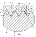
- the plug 24 as a screw 26 has the outer peripheral side an external thread 38 in the form of a standard thread, in particular fine thread (Whitworth), wherein the pertinent external thread 38 in the Figure 2 is shown enlarged and in an installed position, in the the screw 26 is not yet completely screwed into the valve housing 10 is. Seen in the direction of the figure 2 is on the right side the mecanicsechskantausEnglishung (not shown in Figure 2) arranged and on the left side would be to the base part 28, the centering 30th (not shown in Figure 2) connect. Said external thread 38 engages in a corresponding internal thread 40, which also as Regular thread is formed and the part of the component 42, which is the front bottom end of the valve housing 10 of the proportional valve is formed.
- a standard thread in particular fine thread (Whitworth)
- Said external thread 38 engages in a corresponding internal thread 40, which also as Regular thread is formed and the part of the component 42, which is the front bottom end of the valve housing 10 of the proportional valve is formed.
- flank angles A, B from the external thread 38 and internal thread 40 itself differ from each other by 2 to 10 degrees, preferably by 5 degrees. It is further provided that the slope of the external thread 38 and internal thread 40 by 0.01 to 0.3, preferably by 0.05, different from each other are.
- the direction of insertion X is X. vorderst arranged thread 44 with fully made threaded connection with at least one of its flank parts 46 in pressender System with an assignable edge portion 48 of the internal thread 40, and although in the region of the outer circumference 50 of said front thread turn 44.
- the pertinent complete installation situation is shown in Fig.2 not shown, where the opposite in the screw thread 52 is still outside the screw. Yet Fig.2 gives a graphic indication of the complete installation situation the stopper 24 in the proportional valve housing 10.
- the following Flank parts 46a, b, c of the further threads of the external thread 38, which are oriented in the screw X, have in contrast an axial distance to the assignable edge portions 48a, b, c of the internal thread 40 on.
Landscapes
- Engineering & Computer Science (AREA)
- General Engineering & Computer Science (AREA)
- Mechanical Engineering (AREA)
- Magnetically Actuated Valves (AREA)
- Valve Housings (AREA)
- Preventing Unauthorised Actuation Of Valves (AREA)
Description
Am gegenüberliegenden freien Ende der Einschraubstrecke kommt es dazu, dass das Innengewinde des Bauteils an der Stelle des Auslaufs in die Umgebungen in verpreßter Anlage mit dem Außengewinde des Einschraubteils in dessen Einschraubgrund ist, wobei zum Außenumfang des Außengewindes hin die beiden in Einschraubrichtung unmittelbar vorangehenden und benachbarten Flankenteile von Innen- und Außengewinde sich voneinander wegspreizend verlaufen.
Die dahingehenden Parameter und ihre vorgenommenen Paarungen haben sich für die Realisierung der Schraubensicherung im genannten Ventilbereich als besonders zweckmäßig und brauchbar erwiesen. In Einzelfällen, insbesondere in Abhängigkeit von den Durchmesserverhältnissen, der eingesetzten Gewinde sowie der Auswahl der Grundform, wie Trapezgewinde, Rundgewinde etc., können im Rahmen der genannten Unteransprüche, die Flankenwinkel und Steigungen auch anders gewählt sein.
Weitere vorteilhafte Ausführungsformen der Schraubensicherung sind im übrigen Gegenstand der sonstigen Unteransprüche.
Im folgenden wird die erfindungsgemäße Schraubensicherung anhand eines Ausführungsbeispieles nach der Zeichnung näher erläutert. Dabei zeigen in prinzipieller und nicht maßstäblicher Darstellung die
- Fig. 1
- einen Längsschnitt durch Teile eines Proportionalventiles mit am unteren Ende eingedrehten Verschlußstopfen nebst Schraubensicherung;
- Fig. 2
- in vergrößerter Darstellung einen Ausschnitt bezogen auf einen Teil der Gewindegänge der Schraubensicherung bei nicht vollständig eingedrehtem Verschlußstopfen in das Ventilgehäuse nach der Figur 1.
Claims (9)
- Schraubensicherung für den Einsatz in Gehäuseteilen (10) von Ventilen, insbesondere Proportionalventilen, mit einem Einschraubteil (26) mit einem Außengewinde (38), das in ein korrespondierendes Innengewinde (40) in einem das Einschraubteil (26) umfassenden Bauteil (42), insbesondere Gehäuseteil (10), eingreift, wobei die Flankenwinkel (A, B) und die Steigung der genannten Gewinde (38, 40) voneinander verschieden sind, dadurch gekennzeichnet, dass die Flankenwinkel (A, B) von Außen- (38) und Innengewinde (40) um 2° bis 10° voneinander verschieden sind, dass die Steigung von Außen- (38) und Innengewinde (40) um 0,01 bis 0,3 voneinander verschieden sind, dass der in Einschraubrichtung (X) zuvorderst angeordnete Gewindegang (44) bei vollständig hergestellter Gewindeverbindung mit zumindest einem seiner Flankenteile (46) in pressender Anlage mit einem zuordenbaren Flankenteil (48) des Innengewindes (40) ist, und zwar im Bereich des Außenumfanges (50) des Gewindeganges (44), und dass die nachfolgenden Flankenteile (46 a,b,c) der Gewindegänge des Außengewindes (38), die in Einschraubrichtung (X) orientiert sind, einen axialen Abstand zu den zuordenbaren Flankenteilen (48 a,b,c) des Innengewindes (40) aufweisen.
- Schraubensicherung nach Anspruch 1, dadurch gekennzeichnet, dass die Flankenwinkel (A, B) von Außen- (38) und Innengewinde (40) um 5° voneinander verschieden sind.
- Schraubensicherung nach Anspruch 1 oder 2, dadurch gekennzeichnet, dass die Steigung von Außen- (38) und Innengewinde (40) um 0,05 voneinander verschieden sind.
- Schraubensicherung nach einem der Ansprüche 1 bis 3, dadurch gekennzeichnet, dass das Innengewinde (40) des Bauteils (42) ein genormtes Standardgewinde mit einem Flankenwinkel (B) von 60° ist und dass das korrespondierende Außengewinde (38) des Einschraubteils (26) ein genormtes Standard-Gewinde mit einem Flankenwinkel (A) von 55° hat.
- Schraubensicherung nach einem der Ansprüche 1 bis 4, dadurch gekennzeichnet, dass das Außengewinde (38) des Einschraubteils (26) ebenso wie das Innengewinde (40) des Bauteils (42) ein Feingewinde (M10x1) ist, jedoch mit einer um +0,03 höheren oder-0,03 niedrigeren Steigung als das Innengewinde (40).
- Schraubensicherung nach einem der Ansprüche 1 bis 5, dadurch gekennzeichnet, dass das Außen- und Innengewinde (38, 40) jeweils 2 bis 6, vorzugsweise 4 Gewindegänge aufweisen.
- Schraubensicherung nach Anspruch6, dadurch gekennzeichnet, dass das Innengewinde (40) des Bauteils (42) an der Stelle des Auslaufs (54) in die Umgebung in pressender Anlage (58) mit dem Außengewinde (38) des Einschraubteils (26) in dessen Einschraubgrund (56) ist und dass zum Außenumfang (50) des Außengewindes (38) hin die beiden in Einschraubrichtung (X) unmittelbar vorangehenden und benachbarten Flankenteile (62 a,b) von Innen- (40) und Außengewinde (38) sich voneinander wegspreizend verlaufen.
- Schraubensicherung nach einem der Ansprüche 1 bis 7, die als Teil eines Proportionalventils ausgebildet ist, mit einem Ventilgehäuse (10), in dem ein Ventilkolben (18) mit mindestens einer Steuerkante (20) längsverfahrbar geführt ist, die gegenüber einem druckführenden Anschluß (14) im Ventilgehäuse (10) zusammen mit dem Ventilkolben über das Einschraubteil (26) mit Außengewinde (38) in der Art eines Verschlußstopfens (24) reversibel einjustierbar ist.
- Schraubensicherung nach Anspruch 8, dadurch gekennzeichnet, dass der Ventilkolben (18) mittels eines Magnetsystems in der Art eines Schaltmagneten längsverfahrbar im Ventilgehäuse (10) und derart ansteuerbar gegen die resultierende Kraft einer Druckfeder (22) verfahrbar ist, die zwischen Verschlußstopfen (24) und Ventilkolben (18) wirkt.
Applications Claiming Priority (2)
| Application Number | Priority Date | Filing Date | Title |
|---|---|---|---|
| DE10238832 | 2002-08-23 | ||
| DE2002138832 DE10238832A1 (de) | 2002-08-23 | 2002-08-23 | Schraubensicherung |
Publications (2)
| Publication Number | Publication Date |
|---|---|
| EP1391618A1 EP1391618A1 (de) | 2004-02-25 |
| EP1391618B1 true EP1391618B1 (de) | 2005-10-26 |
Family
ID=30775546
Family Applications (1)
| Application Number | Title | Priority Date | Filing Date |
|---|---|---|---|
| EP20030018823 Expired - Lifetime EP1391618B1 (de) | 2002-08-23 | 2003-08-19 | Schraubensicherung |
Country Status (2)
| Country | Link |
|---|---|
| EP (1) | EP1391618B1 (de) |
| DE (2) | DE10238832A1 (de) |
Cited By (3)
| Publication number | Priority date | Publication date | Assignee | Title |
|---|---|---|---|---|
| DE102009051540A1 (de) | 2009-10-30 | 2011-05-05 | Volkswagen Ag | Selbstsichernde Einstelleinrichtung, Fahrzeuglenkung und Verfahren zum Einstellen eines Spiels eines Druckstück in einer Fahrzeuglenkung |
| DE102010043805A1 (de) | 2010-11-11 | 2012-06-14 | Polycom Škofja Loka D.O.O. | Selbstsichernde Einstelleinrichtung und Fahrzeuglenkung |
| DE102015110088A1 (de) * | 2015-06-23 | 2016-12-29 | Maco Technologie Gmbh | Ecklager für ein dreh-kipp-fenster |
Families Citing this family (8)
| Publication number | Priority date | Publication date | Assignee | Title |
|---|---|---|---|---|
| DE102005023441A1 (de) * | 2005-05-20 | 2006-11-30 | BSH Bosch und Siemens Hausgeräte GmbH | Selbstsichernde Gerätefüße |
| DE202007002347U1 (de) * | 2007-02-16 | 2007-04-19 | Böllhoff Verbindungstechnik GmbH | Gewindesicherung für eine Gewindeverbindung |
| DE102013203570A1 (de) * | 2013-03-01 | 2014-09-04 | Mahle International Gmbh | Schraubanordnung |
| JP2016524680A (ja) * | 2013-07-03 | 2016-08-18 | ▲許▼松林XU, Songlin | 緩み止め円柱状ねじ部材 |
| JP2016522374A (ja) * | 2013-07-03 | 2016-07-28 | ▲許▼松林XU, Songlin | 緩み止め円柱状ねじ部材 |
| CN103291730A (zh) * | 2013-07-03 | 2013-09-11 | 许松林 | 一种防松动圆柱螺纹件 |
| WO2018119847A1 (zh) * | 2016-12-29 | 2018-07-05 | 诠丰精密工具股份有限公司 | 螺纹螺合构造 |
| DE102024128687A1 (de) | 2024-10-04 | 2026-04-09 | Bayerische Motoren Werke Aktiengesellschaft | Verfahren zur Montage eines Verschlusses an einem Druckbehälter |
Family Cites Families (7)
| Publication number | Priority date | Publication date | Assignee | Title |
|---|---|---|---|---|
| US3133578A (en) * | 1962-10-26 | 1964-05-19 | Milton A Moskovitz | Self-locking bolt |
| NL129061C (de) * | 1963-07-18 | |||
| US5672037A (en) * | 1994-11-01 | 1997-09-30 | Iwata Bolt Kabushiki Kaisha | Loosening and dislodging preventing screw |
| JP2989129B2 (ja) * | 1995-10-09 | 1999-12-13 | イワタボルト株式会社 | 雄ねじ |
| DE19621284A1 (de) * | 1996-05-25 | 1997-11-27 | Behr Gmbh & Co | Befestigungselement, insbesondere aus Kunststoff hergestellte Ablaßschraube |
| DE19953209A1 (de) * | 1999-11-05 | 2001-06-13 | Fluidtech Gmbh | Ventil, insbesondere Druckregelventil |
| DE10023388A1 (de) * | 2000-05-12 | 2001-11-15 | Mannesmann Rexroth Ag | Hydraulisches Gerät |
-
2002
- 2002-08-23 DE DE2002138832 patent/DE10238832A1/de not_active Withdrawn
-
2003
- 2003-08-19 DE DE50301464T patent/DE50301464D1/de not_active Expired - Lifetime
- 2003-08-19 EP EP20030018823 patent/EP1391618B1/de not_active Expired - Lifetime
Cited By (3)
| Publication number | Priority date | Publication date | Assignee | Title |
|---|---|---|---|---|
| DE102009051540A1 (de) | 2009-10-30 | 2011-05-05 | Volkswagen Ag | Selbstsichernde Einstelleinrichtung, Fahrzeuglenkung und Verfahren zum Einstellen eines Spiels eines Druckstück in einer Fahrzeuglenkung |
| DE102010043805A1 (de) | 2010-11-11 | 2012-06-14 | Polycom Škofja Loka D.O.O. | Selbstsichernde Einstelleinrichtung und Fahrzeuglenkung |
| DE102015110088A1 (de) * | 2015-06-23 | 2016-12-29 | Maco Technologie Gmbh | Ecklager für ein dreh-kipp-fenster |
Also Published As
| Publication number | Publication date |
|---|---|
| EP1391618A1 (de) | 2004-02-25 |
| DE10238832A1 (de) | 2004-03-04 |
| DE50301464D1 (de) | 2005-12-01 |
Similar Documents
| Publication | Publication Date | Title |
|---|---|---|
| EP3004702B1 (de) | Kombination aus einem gehäuse und einem ventil | |
| DE102013210645A1 (de) | Einstellschraubverbindung für ein Ventil der Hydraulik und Ventil der Hydraulik | |
| EP1540234A1 (de) | Adapter-zwischenring für ein einschraubteil eines fluid-stecksystems | |
| EP1391618A1 (de) | Schraubensicherung | |
| WO1989007221A1 (en) | Clamping joint for pipes | |
| DE10023388A1 (de) | Hydraulisches Gerät | |
| EP3172427A1 (de) | Hochdruckanschlussvorrichtung | |
| EP2541110B1 (de) | Pneumatisches Ventil in Schieberbauart | |
| EP1348900B1 (de) | Rohrbruchventil	 | |
| EP1564462B1 (de) | Rohrbruchventil | |
| AT506991B1 (de) | Verbindungselement | |
| DE20009766U1 (de) | Ventil | |
| EP3537017A1 (de) | Ventil | |
| WO2006092445A2 (de) | Bauteil mit aussengewinde zum einsetzen in ein innengewinde | |
| EP2165101B1 (de) | Stellanordnung | |
| EP4234481A1 (de) | Zapfventil | |
| DE4442243C2 (de) | Armatur für ein Thermostatventil | |
| WO2008043773A1 (de) | Losdrehsicherungsanordnung für ein einschraubelement | |
| DE202023107374U1 (de) | Hochdruck-Entlüftungsarmatur, insbesondere Hochdruck-Entlüftungsstopfen | |
| DE29905140U1 (de) | Eckventil | |
| DE102022118129A1 (de) | Armatur mit Ventilelement | |
| DE4122982C2 (de) | ||
| EP0746713B1 (de) | Hydraulisches einsatzventil | |
| WO2016177499A1 (de) | Schlauchschelle | |
| DE102004006664A1 (de) | Rohrbruchventil |
Legal Events
| Date | Code | Title | Description |
|---|---|---|---|
| PUAI | Public reference made under article 153(3) epc to a published international application that has entered the european phase |
Free format text: ORIGINAL CODE: 0009012 |
|
| AK | Designated contracting states |
Kind code of ref document: A1 Designated state(s): AT BE BG CH CY CZ DE DK EE ES FI FR GB GR HU IE IT LI LU MC NL PT RO SE SI SK TR |
|
| AX | Request for extension of the european patent |
Extension state: AL LT LV MK |
|
| 17P | Request for examination filed |
Effective date: 20040707 |
|
| 17Q | First examination report despatched |
Effective date: 20040816 |
|
| AKX | Designation fees paid |
Designated state(s): DE FR GB |
|
| RAP1 | Party data changed (applicant data changed or rights of an application transferred) |
Owner name: HYDAC ELECTRONIC GMBH |
|
| GRAP | Despatch of communication of intention to grant a patent |
Free format text: ORIGINAL CODE: EPIDOSNIGR1 |
|
| GRAS | Grant fee paid |
Free format text: ORIGINAL CODE: EPIDOSNIGR3 |
|
| GRAA | (expected) grant |
Free format text: ORIGINAL CODE: 0009210 |
|
| AK | Designated contracting states |
Kind code of ref document: B1 Designated state(s): DE FR GB |
|
| REG | Reference to a national code |
Ref country code: GB Ref legal event code: FG4D Free format text: NOT ENGLISH |
|
| GBT | Gb: translation of ep patent filed (gb section 77(6)(a)/1977) |
Effective date: 20051026 |
|
| REF | Corresponds to: |
Ref document number: 50301464 Country of ref document: DE Date of ref document: 20051201 Kind code of ref document: P |
|
| ET | Fr: translation filed | ||
| PLBE | No opposition filed within time limit |
Free format text: ORIGINAL CODE: 0009261 |
|
| STAA | Information on the status of an ep patent application or granted ep patent |
Free format text: STATUS: NO OPPOSITION FILED WITHIN TIME LIMIT |
|
| 26N | No opposition filed |
Effective date: 20060727 |
|
| PGFP | Annual fee paid to national office [announced via postgrant information from national office to epo] |
Ref country code: GB Payment date: 20110613 Year of fee payment: 9 |
|
| PGFP | Annual fee paid to national office [announced via postgrant information from national office to epo] |
Ref country code: FR Payment date: 20110727 Year of fee payment: 9 |
|
| GBPC | Gb: european patent ceased through non-payment of renewal fee |
Effective date: 20120819 |
|
| REG | Reference to a national code |
Ref country code: FR Ref legal event code: ST Effective date: 20130430 |
|
| PG25 | Lapsed in a contracting state [announced via postgrant information from national office to epo] |
Ref country code: GB Free format text: LAPSE BECAUSE OF NON-PAYMENT OF DUE FEES Effective date: 20120819 |
|
| PG25 | Lapsed in a contracting state [announced via postgrant information from national office to epo] |
Ref country code: FR Free format text: LAPSE BECAUSE OF NON-PAYMENT OF DUE FEES Effective date: 20120831 |
|
| PGFP | Annual fee paid to national office [announced via postgrant information from national office to epo] |
Ref country code: DE Payment date: 20170831 Year of fee payment: 15 |
|
| REG | Reference to a national code |
Ref country code: DE Ref legal event code: R119 Ref document number: 50301464 Country of ref document: DE |
|
| PG25 | Lapsed in a contracting state [announced via postgrant information from national office to epo] |
Ref country code: DE Free format text: LAPSE BECAUSE OF NON-PAYMENT OF DUE FEES Effective date: 20190301 |