EP1391522A2 - Elektrode sowie Verfahren zu deren Anordnung in Elektro-Lichtbogenöfen - Google Patents
Elektrode sowie Verfahren zu deren Anordnung in Elektro-Lichtbogenöfen Download PDFInfo
- Publication number
- EP1391522A2 EP1391522A2 EP03014329A EP03014329A EP1391522A2 EP 1391522 A2 EP1391522 A2 EP 1391522A2 EP 03014329 A EP03014329 A EP 03014329A EP 03014329 A EP03014329 A EP 03014329A EP 1391522 A2 EP1391522 A2 EP 1391522A2
- Authority
- EP
- European Patent Office
- Prior art keywords
- electrode
- reinforcement
- electrode core
- furnace
- core
- Prior art date
- Legal status (The legal status is an assumption and is not a legal conclusion. Google has not performed a legal analysis and makes no representation as to the accuracy of the status listed.)
- Withdrawn
Links
- 238000010891 electric arc Methods 0.000 title claims abstract description 11
- 230000002787 reinforcement Effects 0.000 claims abstract description 65
- 239000000155 melt Substances 0.000 claims abstract description 19
- 238000000034 method Methods 0.000 claims abstract description 16
- 239000002893 slag Substances 0.000 claims abstract description 11
- 239000004020 conductor Substances 0.000 claims abstract description 8
- OKTJSMMVPCPJKN-UHFFFAOYSA-N Carbon Chemical compound [C] OKTJSMMVPCPJKN-UHFFFAOYSA-N 0.000 claims description 14
- 229910052799 carbon Inorganic materials 0.000 claims description 9
- 238000001816 cooling Methods 0.000 claims description 8
- 238000010438 heat treatment Methods 0.000 claims description 8
- 239000007788 liquid Substances 0.000 claims description 8
- 239000000919 ceramic Substances 0.000 claims description 6
- 229910002804 graphite Inorganic materials 0.000 claims description 5
- 239000010439 graphite Substances 0.000 claims description 5
- 239000007769 metal material Substances 0.000 claims description 4
- 239000002184 metal Substances 0.000 claims description 3
- 238000010310 metallurgical process Methods 0.000 claims description 3
- 230000007935 neutral effect Effects 0.000 abstract 1
- 239000000463 material Substances 0.000 description 10
- 238000002844 melting Methods 0.000 description 7
- 230000008018 melting Effects 0.000 description 7
- 238000007654 immersion Methods 0.000 description 4
- 239000010410 layer Substances 0.000 description 3
- 239000011241 protective layer Substances 0.000 description 3
- HBMJWWWQQXIZIP-UHFFFAOYSA-N silicon carbide Chemical compound [Si+]#[C-] HBMJWWWQQXIZIP-UHFFFAOYSA-N 0.000 description 3
- 229910010271 silicon carbide Inorganic materials 0.000 description 3
- 230000003647 oxidation Effects 0.000 description 2
- 238000007254 oxidation reaction Methods 0.000 description 2
- 229910018072 Al 2 O 3 Inorganic materials 0.000 description 1
- 241000272165 Charadriidae Species 0.000 description 1
- ZAMOUSCENKQFHK-UHFFFAOYSA-N Chlorine atom Chemical compound [Cl] ZAMOUSCENKQFHK-UHFFFAOYSA-N 0.000 description 1
- XUIMIQQOPSSXEZ-UHFFFAOYSA-N Silicon Chemical compound [Si] XUIMIQQOPSSXEZ-UHFFFAOYSA-N 0.000 description 1
- 229910000831 Steel Inorganic materials 0.000 description 1
- ATJFFYVFTNAWJD-UHFFFAOYSA-N Tin Chemical compound [Sn] ATJFFYVFTNAWJD-UHFFFAOYSA-N 0.000 description 1
- QVGXLLKOCUKJST-UHFFFAOYSA-N atomic oxygen Chemical compound [O] QVGXLLKOCUKJST-UHFFFAOYSA-N 0.000 description 1
- 230000005540 biological transmission Effects 0.000 description 1
- 238000006243 chemical reaction Methods 0.000 description 1
- 239000000460 chlorine Substances 0.000 description 1
- 229910052801 chlorine Inorganic materials 0.000 description 1
- 238000011161 development Methods 0.000 description 1
- 230000018109 developmental process Effects 0.000 description 1
- 239000000428 dust Substances 0.000 description 1
- 230000005611 electricity Effects 0.000 description 1
- 239000004744 fabric Substances 0.000 description 1
- 238000010309 melting process Methods 0.000 description 1
- 229910052760 oxygen Inorganic materials 0.000 description 1
- 239000001301 oxygen Substances 0.000 description 1
- 230000001681 protective effect Effects 0.000 description 1
- 238000004064 recycling Methods 0.000 description 1
- 229910052710 silicon Inorganic materials 0.000 description 1
- 239000010703 silicon Substances 0.000 description 1
- 239000007787 solid Substances 0.000 description 1
- 239000011343 solid material Substances 0.000 description 1
- 238000005507 spraying Methods 0.000 description 1
- 239000010959 steel Substances 0.000 description 1
- 239000004753 textile Substances 0.000 description 1
- XLYOFNOQVPJJNP-UHFFFAOYSA-N water Substances O XLYOFNOQVPJJNP-UHFFFAOYSA-N 0.000 description 1
Images
Classifications
-
- F—MECHANICAL ENGINEERING; LIGHTING; HEATING; WEAPONS; BLASTING
- F27—FURNACES; KILNS; OVENS; RETORTS
- F27D—DETAILS OR ACCESSORIES OF FURNACES, KILNS, OVENS OR RETORTS, IN SO FAR AS THEY ARE OF KINDS OCCURRING IN MORE THAN ONE KIND OF FURNACE
- F27D11/00—Arrangement of elements for electric heating in or on furnaces
- F27D11/08—Heating by electric discharge, e.g. arc discharge
-
- C—CHEMISTRY; METALLURGY
- C21—METALLURGY OF IRON
- C21C—PROCESSING OF PIG-IRON, e.g. REFINING, MANUFACTURE OF WROUGHT-IRON OR STEEL; TREATMENT IN MOLTEN STATE OF FERROUS ALLOYS
- C21C5/00—Manufacture of carbon-steel, e.g. plain mild steel, medium carbon steel or cast steel or stainless steel
- C21C5/52—Manufacture of steel in electric furnaces
- C21C5/5211—Manufacture of steel in electric furnaces in an alternating current [AC] electric arc furnace
-
- C—CHEMISTRY; METALLURGY
- C21—METALLURGY OF IRON
- C21C—PROCESSING OF PIG-IRON, e.g. REFINING, MANUFACTURE OF WROUGHT-IRON OR STEEL; TREATMENT IN MOLTEN STATE OF FERROUS ALLOYS
- C21C5/00—Manufacture of carbon-steel, e.g. plain mild steel, medium carbon steel or cast steel or stainless steel
- C21C5/52—Manufacture of steel in electric furnaces
- C21C5/5229—Manufacture of steel in electric furnaces in a direct current [DC] electric arc furnace
-
- F—MECHANICAL ENGINEERING; LIGHTING; HEATING; WEAPONS; BLASTING
- F27—FURNACES; KILNS; OVENS; RETORTS
- F27B—FURNACES, KILNS, OVENS OR RETORTS IN GENERAL; OPEN SINTERING OR LIKE APPARATUS
- F27B3/00—Hearth-type furnaces, e.g. of reverberatory type; Electric arc furnaces ; Tank furnaces
- F27B3/08—Hearth-type furnaces, e.g. of reverberatory type; Electric arc furnaces ; Tank furnaces heated electrically, with or without any other source of heat
- F27B3/085—Arc furnaces
-
- F—MECHANICAL ENGINEERING; LIGHTING; HEATING; WEAPONS; BLASTING
- F27—FURNACES; KILNS; OVENS; RETORTS
- F27B—FURNACES, KILNS, OVENS OR RETORTS IN GENERAL; OPEN SINTERING OR LIKE APPARATUS
- F27B3/00—Hearth-type furnaces, e.g. of reverberatory type; Electric arc furnaces ; Tank furnaces
- F27B3/10—Details, accessories or equipment, e.g. dust-collectors, specially adapted for hearth-type furnaces
- F27B3/20—Arrangements of heating devices
-
- F—MECHANICAL ENGINEERING; LIGHTING; HEATING; WEAPONS; BLASTING
- F27—FURNACES; KILNS; OVENS; RETORTS
- F27D—DETAILS OR ACCESSORIES OF FURNACES, KILNS, OVENS OR RETORTS, IN SO FAR AS THEY ARE OF KINDS OCCURRING IN MORE THAN ONE KIND OF FURNACE
- F27D1/00—Casings; Linings; Walls; Roofs
- F27D1/0003—Linings or walls
- F27D1/0006—Linings or walls formed from bricks or layers with a particular composition or specific characteristics
-
- H—ELECTRICITY
- H05—ELECTRIC TECHNIQUES NOT OTHERWISE PROVIDED FOR
- H05B—ELECTRIC HEATING; ELECTRIC LIGHT SOURCES NOT OTHERWISE PROVIDED FOR; CIRCUIT ARRANGEMENTS FOR ELECTRIC LIGHT SOURCES, IN GENERAL
- H05B7/00—Heating by electric discharge
- H05B7/02—Details
- H05B7/06—Electrodes
- H05B7/08—Electrodes non-consumable
- H05B7/085—Electrodes non-consumable mainly consisting of carbon
-
- F—MECHANICAL ENGINEERING; LIGHTING; HEATING; WEAPONS; BLASTING
- F27—FURNACES; KILNS; OVENS; RETORTS
- F27D—DETAILS OR ACCESSORIES OF FURNACES, KILNS, OVENS OR RETORTS, IN SO FAR AS THEY ARE OF KINDS OCCURRING IN MORE THAN ONE KIND OF FURNACE
- F27D1/00—Casings; Linings; Walls; Roofs
- F27D2001/0046—Means to facilitate repair or replacement or prevent quick wearing
- F27D2001/005—Removable part or structure with replaceable elements
-
- F—MECHANICAL ENGINEERING; LIGHTING; HEATING; WEAPONS; BLASTING
- F27—FURNACES; KILNS; OVENS; RETORTS
- F27D—DETAILS OR ACCESSORIES OF FURNACES, KILNS, OVENS OR RETORTS, IN SO FAR AS THEY ARE OF KINDS OCCURRING IN MORE THAN ONE KIND OF FURNACE
- F27D99/00—Subject matter not provided for in other groups of this subclass
- F27D99/0001—Heating elements or systems
- F27D99/0006—Electric heating elements or system
- F27D2099/0021—Arc heating
-
- Y—GENERAL TAGGING OF NEW TECHNOLOGICAL DEVELOPMENTS; GENERAL TAGGING OF CROSS-SECTIONAL TECHNOLOGIES SPANNING OVER SEVERAL SECTIONS OF THE IPC; TECHNICAL SUBJECTS COVERED BY FORMER USPC CROSS-REFERENCE ART COLLECTIONS [XRACs] AND DIGESTS
- Y02—TECHNOLOGIES OR APPLICATIONS FOR MITIGATION OR ADAPTATION AGAINST CLIMATE CHANGE
- Y02P—CLIMATE CHANGE MITIGATION TECHNOLOGIES IN THE PRODUCTION OR PROCESSING OF GOODS
- Y02P10/00—Technologies related to metal processing
- Y02P10/20—Recycling
Definitions
- the invention relates to an electrode for electric arc furnaces in which metallurgical Processes, such as melting and / or processing processes, performed are, wherein the electrode comprises a current-conducting electrode core. Moreover The invention relates to a method for arranging a current-carrying electrode in an electric arc furnace, especially an arc reduction furnace, the a lower furnace part for receiving the melt and an upper furnace part comprises, the electrode being introduced through an opening in the upper furnace part and extends into the oven interior.
- Electric arc furnaces use the energy required for them ongoing metallurgical processes is required as electrical energy Electrodes introduced. Electric arc furnaces are used, for example, in recycling processes, used especially for melting steel scrap. at In some known processes, the electrodes are immersed in the process Melt or partially in the melt introduced for the process on. Carbon or graphite electrodes are usually used for power transmission used.
- DE 36 03 948 A1 discloses an arc reduction furnace. To prevent, that the electrodes in the free furnace space between the furnace cover and the Slag bath are exposed to the aggressive atmosphere of the furnace interior and the aggressive furnace atmosphere to massive radial burnup Is known from this document to provide electrodes in the furnace, which protrude parallel to the electrodes into the furnace interior and shield the electrodes from the oxygen and dust-containing atmosphere.
- Electrodes with an electrode core are also known for preventing of oxidation through the furnace atmosphere with wafer-thin protective layers is provided along its lateral surface.
- Such protective layers only serve as protection against oxidation and do not hold chemically extremely aggressive melts stood, for example special melts that are rinsed with chlorine. On the other hand for certain special melts it is undesirable if the electrode carbon passes into the melt.
- the invention is therefore based on the object of developing an electrode in such a way that that even with chemically extremely aggressive melts or with Melt that would be adulterated by electrode carbon can be used can.
- the electrode core including the towards the furnace bottom of the electrode core end or the electrode core tip a reinforcement from one opposite the melt and the slag process-neutral and made of an electrically conductive material, and that the reinforcement at least the electrode area that is in contact with the slag or the melt comes, completely envelops and thus the contact of the electrode core prevented with the slag / melt.
- the reinforcement behaves towards the melt and / or the slag or the melting material that has not yet melted down over the entire process process-neutral. Because of this property and because of that the floor the electrode is completely closed off from the weld pool, the electrode can not be attacked by chemically aggressive media; also can no carbon can escape from the electrode into the weld pool. Overall will get a very low-wear or wear-resistant electrode, where necessary.
- a repositioning device can be dispensed with. They can also Electrodes can also be used for those melts that are not in contact with Carbon may come.
- the reinforcement can be arranged on the electrode core in the manner of a protective cap preferably the process-neutral reinforcement also extends over the electrode area that is exposed to the furnace atmosphere.
- the reinforcement is then a complete covering of the outer surface and the electrode base trained and protects the electrode core over its entire length.
- the reinforcement is directly on the electrode core applied, for example, by the reinforcement material directly is sprayed on.
- the reinforcement materials should be one thermal expansion coefficient corresponding essentially to the material of the electrode core have temperature differences of the electrode to avoid and prevent internal stresses during use, that the reinforcement layer flakes off the electrode core.
- the reinforcement is separate crucible-like receiving area formed for the electrode core, in which the Electrode core is insertable. This creates a strong and dense reinforcement for reached the electrode core.
- the reinforcement can be attached to the arc furnace separately and then the electrode core is moved into the crucible-like receiving area become.
- the reinforcement and the electrode core can be outside of the furnace, preferably close to the furnace, brought together and then be introduced into the oven as a unit.
- Electrodes and Reinforcement form a detachably connected unit, for example through a bolt connection; they can also be unsolvable, if necessary, by a Press fit to be connected. It is recommended for a press fit itself, the electrode core and the crucible-like receiving area are conical in order to press the electrode core into the crucible under tight pressure to be able to.
- the reinforcement preferably consists of a technical ceramic with good electrical conductivity.
- a technical ceramic with good electrical conductivity.
- SiSiC silicon infiltrated silicon carbide
- mixed ceramics based on Al 2 O 3 , TiC or TiN can be used.
- Technical ceramics are also known, for example, which have an electrical resistance at approximately 1000 ° C., which is only 1% of its value at room temperature.
- the thickness of the reinforcement depends on the dimensions of the electrodes and the required performance. For mechanical reasons, the thickness should not are less than about 2 mm.
- a different thermal expansion behavior of the material of the electrode core and to be able to compensate for the reinforcement material should be between an electrically conductive buffer medium for the electrode core and the reinforcement be arranged.
- the electrode core and the reinforcement stretch along the length of the weld pool to different degrees due to the heat input.
- the intermediate or Buffer medium should be designed so that there are fluctuating distances between Compensate electrode core and reinforcement or different volume profiles can fill out.
- the medium is preferably pourable, for example in a powdery or spherical, in the broadest sense granular state.
- Examples of such a small-grain material are graphite or metal chips. It can also be a liquid as an intermediate medium in the intermediate space be filled. It is also advantageous to have textile fabric metallized in the intermediate gap or bring in metal mesh that provides a power connection between Form core and reinforcement and work as a buffer layer.
- a heating element acting in the intermediate space preferably a SiC heating element to be provided.
- Solid, small-grain, pourable media with low Melting point are introduced shortly before or at the start of the process transferred from heat to the liquid state, so that none in the space cavities that obstruct the flow of electricity remain.
- the electrode can, in particular made of graphite, also have an electrode core made of a metallic material. This is particularly recommended for melts that are never with Carbon may be mixed.
- an electrode core from one Metallic material should have cooling channels that are used to cool one flow through liquid or gaseous medium. This leads to one Continuous electrode core. This has the further advantage that the reinforcement is cooled indirectly and thus its wear is minimized.
- the electrodes according to the invention can be used in all types of arc furnaces be used. You can use both three-phase and direct current furnaces Find use. Such electrodes should preferably be used in arc reduction furnaces are used, their field of application thus on chemical-physical Special melting processes can be expanded. Here you can especially used in melts that are chemically very aggressive are.
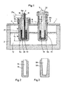
- an electric arc furnace 1 for example an arc reduction furnace, with a lower furnace part 2 and an upper furnace part 3 in shape a cover into which two current-conducting electrodes 4, 5 are introduced.
- the Oven 1 itself has a refractory lining and / or cooling elements (not shown), like water-flowed heat sinks. If for each metallurgical melting and / or processing a closed Should be necessary, as shown here, the electrodes 4, 5 gas-tight through openings 6, 7 in the lid.
- the electrodes 4, 5 have in common that they have an electrode core 8a, b and a reinforcement 9a, b, the end 10 or the tip and the outer surface 11 of the electrode core 8a, b surrounds.
- the reinforcement 9a, b has the task chemical-physical reactions between the electrode cores 8a, b and to avoid the molten bath 12.
- the reinforcement 9a, b extends here via the electrode area 13, which dips into the molten bath 12, as also over the electrode area 14, which is exposed to the furnace atmosphere.
- This crucible is by means of a collar 17 on suitable stilts 18 or supports on the Oven ceiling or hung in the oven house. It extends into the weld pool 12.
- the electrode core 8a then becomes vertical from above for the introduction of current (see arrow direction 19) into the interior of the receiving area. It it is advisable to use pourable medium 20 in a preparatory step or material with a low melting point in the lower part of the recording area contribute. Then, when the electrode core 8a is positioned, the between the outer wall of the electrode core 8a and the inner wall of the Intermediate space 15 resulting in the receiving area or gap with further pourable Material 20 filled up.
- a heating element is placed in the intermediate space 15, for example an SiC heating conductor, 21 arranged vertically, which has a Line 21a is supplied with energy from the outside.
- This heating element 21 is said melt solid material 20 in space 15 and thus optimal conditions for a current flow from the electrode core 8a through the medium and create the outer reinforcement 9a.
- the intermediate material also serves as Buffer or compensation element compared to a different thermal expansion behavior of the electrode core and the reinforcement. After completion The process and cooling of the furnace will turn this medium back on solidify. To avoid tension when the medium solidifies can be a conical design of electrode core or at least the inside the reinforcement. Because the electrical core is not in If the melt comes into contact, it is hardly exposed to wear.
- the electrode 5 shown on the right shows an embodiment which can be variably adjusted with regard to its immersion depth.
- the electrode core 8b in the example shown a carbon or a graphite electrode, is inserted into the separate crucible-like receiving area of the reinforcement 9b, in particular outside the furnace 1, and the electrode core 8b and the upper part of the receiving area or the reinforcement 9b can be detached with a common bolt 22 connected.
- a resulting intermediate space 15 is filled with a conductive material 20, as in the case of the left electrode, and the electrode is guided as a unit into the furnace 1.
- the reinforcement 9c as a protective layer was applied directly to the electrode core 8c. This creates a direct electrical contact between reinforcement and Electrode core reached. Then the electrode core 8c and reinforcement 9c are in one piece non-detachable component that together in the oven and again are movable out.
- the electrode core 8d has a conical shape and fits as Press fit can be pushed into a reinforcement 9d, with a good current flow arises between the two parts.
- the reinforcement 9d may also be conical. It is also possible in these embodiments, too to provide an electrically conductive intermediate layer.
Landscapes
- Engineering & Computer Science (AREA)
- Mechanical Engineering (AREA)
- General Engineering & Computer Science (AREA)
- Chemical & Material Sciences (AREA)
- Materials Engineering (AREA)
- Organic Chemistry (AREA)
- Metallurgy (AREA)
- Manufacturing & Machinery (AREA)
- Physics & Mathematics (AREA)
- Plasma & Fusion (AREA)
- Vertical, Hearth, Or Arc Furnaces (AREA)
- Furnace Details (AREA)
- Discharge Heating (AREA)
Abstract
Description
- Fig. 1
- schematisch als Schnittdarstellung einen Schmelzofen mit zwei Elektroden in unterschiedlicher Ausführungsform;
- Fig. 2
- schematisch als Schnittdarstetellung einen Elektrodenkern mit einer unmittelbar bzw. direkt durch Auftragen oder Aufspritzen aufgebrachten Bewehrung;
- Fig. 3
- schematisch als Schnittdarstellung eine über einen Presssitz verbundene Einheit aus Elektrodenkem und Bewehrung.
- 1
- Elektro-Lichtbogenofen
- 2
- unteres Ofenteil
- 3
- oberes Ofenteil (Deckel)
- 4
- Elektrode
- 5
- Elektrode
- 6
- Öffnung im Deckel
- 7
- Öffnung im Deckel
- 8a-d
- Elektrodenkern
- 9a-d
- Bewehrung
- 10
- Elektrodenkemende
- 11
- Mantelfläche des Elektrodenkerns
- 12
- schmelzflüssiges Bad
- 13
- eingetauchter Elektodenbereich
- 14
- Elektrodenbereich mit Kontakt zur Ofenatmosphäre
- 15
- Zwischenraum
- 16
- Kühlkanäle
- 17
- Kragen
- 18
- Stelzen
- 19
- Pfeilrichtung
- 20
- schüttfähiges Medium
- 21
- Heizelement
- 21a
- Versorgungsleitung für das Heizelement
- 22
- Bolzen
- xE
- Eintauchtiefe
Claims (17)
- Elektrode für Elektro-Lichtbogenöfen (1), in denen metallurgische Prozesse durchgeführt werden, wobei die Elektrode (4, 5) einen stromleitenden Elektrodenkern (8a-d) umfasst,
dadurch gekennzeichnet, dass der Elektrodenkern (8a-d) einschließlich des in Richtung Ofenboden weisenden Elektrodenkernendes (10) eine Bewehrung (9a-d) aus einem gegenüber der Schmelze und der Schlacke prozessneutralen und aus einem elektrisch leitfähigen Material aufweist, und dass die Bewehrung (9a-d) mindestens den Elektrodenbereich (13), der in Kontakt mit der Schlacke oder der Schmelze (12) kommt, gänzlich umhüllt. - Elektrode nach Anspruch 1,
dadurch gekennzeichnet, dass die Bewehrung (9a-d) sich auch über den Elektrodenbereich (14), der der Ofenatmosphäre ausgesetzt ist, erstreckt. - Elektrode nach Anspruch 1 oder 2,
dadurch gekennzeichnet, dass die Bewehrung (9a,b,d) als separater tiegelartiger Aufnahmebereich für den Elektrodernkem (8a,b,d) ausgebildet ist, in den der Elektrodenkem einführbar ist. - Elektrode nach einem der Ansprüche 1 bis 3,
dadurch gekennzeichnet, dass der tiegelartige Aufnahmebereich der Bewehrung (9b) mit dem darin eingeführten Elektrodenkern (8b) lösbar verbunden ist. - Elektrode nach einem der Ansprüche 1 bis 4,
dadurch gekennzeichnet, dass das Außenmaß des Elektrodenkerns (8d) sich so zum Innenmaß des tiegelartigen Aufnahmebereichs der Bewehrung (9d) verhält, dass der Elektrodenkern darin unter einem Presssitz eingeführt ist, wobei die Form des Elektrodenkerns und der Bewehrung vorzugsweise konisch verlaufen. - Elektrode nach einem der Ansprüche 1 bis 5,
dadurch gekennzeichnet, dass zwischen Elektrodenkern (8a,b) und der Bewehrung (9a,b) ein elektrisch leitendes und insbesondere zusätzlich gut wärmeleitendes Medium (20) angeordnet ist. - Elektrode nach Anspruch 6,
dadurch gekennzeichnet, dass zwischen Elektrodenkern (8a,b) und Bewehrung (9a,b) ein Zwischenraum (15) ist, der mit dem elektrisch leitenden Medium (20) aufgefüllt ist. - Elektrode nach Anspruch 7,
dadurch gekennzeichnet, dass das Medium (20) zum Auffüllen des Zwischenraums (15) schüttfähig und hierbei pulverförmig oder kugelförmig oder flüssig ist oder das Medium zum Auffüllen des Zwischenraums ein Metallgewebe ist. - Elektrode nach Anspruch 8,
dadurch gekennzeichnet, dass diese ein im Zwischenraum (15) wirkendes Heizelement (21) umfasst, um noch nicht flüssiges Auffüll-Medium (20) im Zwischenraum (15) in den flüssigen Zustand zu überführen. - Elektrode nach Anspruch 1 oder 2,
dadurch gekennzeichnet, dass die Bewehrung (9c) unmittelbar auf den Elektrodenkern (8c) aufgebracht ist. - Elektrode nach einem der vorherigen Ansprüche,
dadurch gekennzeichnet, dass die Bewehrung (9a-d) aus einer elektrisch leitfähigen Keramik oder einem synthetischen, hitzebeständigen und elektrisch leitenden Material besteht. - Elektrode nach einem der vorherigen Ansprüche,
dadurch gekennzeichnet, dass der Elektrodenkern aus einem metallischen Material (8a) oder aus Kohlenstoff, insbesondere aus Graphit (8b), besteht. - Elektrode nach Anspruch 12,
dadurch gekennzeichnet, dass ein Elektrodenkern, insbesondere der aus einem metallischen Material, Kühlkanäle (16) aufweist, die zur Kühlung von einem flüssigen oder gasförmigen Medium durchströmt werden. - Verfahren zum Anordnen einer stromführenden Elektrode (4, 5) nach einem der Ansprüche 1 bis 13 in einem Elektro-Lichtbogenofen (1), insbesondere Lichtbogenreduktionsofen, der einen unteren Ofenteil (2) zur Aufnahme der Schmelze (12) und einen oberen Ofenteil (3) umfasst, wobei die Elektrode (4, 5) durch eine Öffnung (6, 7) im oberen Ofenteil (3) eingebracht wird und sich in das Ofeninnere erstreckt,
dadurch gekennzeichnet, dass in eine separate Elektrodenbewehrung (9a,b,d), die aus einem gegenüber der Schmelze und/oder der Schlacke prozessneutralen und aus einem elektrisch leitfähigen Material besteht und die den Elektroderkern (8a,b,d) einschließlich des in Richtung Ofenboden weisenden Elektrodemkernendes (10) umhüllt und somit einen Kontakt der Elektrode mit der Schlacke oder Schmelze (12) verhindert, der Elektrodenkern (8a,b,d) eingeführt wird. - Verfahren nach Anspruch 14,
dadurch gekennzeichnet, dass die separate Bewehrung (9a) stationär im oberen Ofenteil (3) angeordnet, anschließend der Elektrodenkern (8a) in die Bewehrung (9a) lösbar eingeführt wird und nach Bedarf wieder ausgeführt wird. - Verfahren nach Anspruch 14,
dadurch gekennzeichnet, dass der Elektrodenkern (8b) des Ofens in die Bewehrung (9b) eingeführt ist, der Elektrodenkern und die Bewehrung zu einer Einheit lösbar miteinander verbunden werden und anschließend die Einheit im Ofenraum positioniert wird. - Verfahren nach einem der Ansprüche 14 bis 16,
dadurch gekennzeichnet, dass ein sich zwischen der Außenwand des Elektrodenkerns (8a,b) und der Innenwand der Bewehrung (9a,b) verbleibender Zwischenraum (15) mit einem elektrisch leitfähigem Medium (20) aufgefüllt wird.
Applications Claiming Priority (2)
| Application Number | Priority Date | Filing Date | Title |
|---|---|---|---|
| DE10237759 | 2002-08-17 | ||
| DE10237759A DE10237759A1 (de) | 2002-08-17 | 2002-08-17 | Elektrode sowie Verfahren zu deren Anordnung in Elektro-Lichtbogenöfen |
Publications (2)
| Publication Number | Publication Date |
|---|---|
| EP1391522A2 true EP1391522A2 (de) | 2004-02-25 |
| EP1391522A3 EP1391522A3 (de) | 2008-01-23 |
Family
ID=30775393
Family Applications (1)
| Application Number | Title | Priority Date | Filing Date |
|---|---|---|---|
| EP03014329A Withdrawn EP1391522A3 (de) | 2002-08-17 | 2003-06-26 | Elektrode sowie Verfahren zu deren Anordnung in Elektro-Lichtbogenöfen |
Country Status (4)
| Country | Link |
|---|---|
| US (1) | US20040066830A1 (de) |
| EP (1) | EP1391522A3 (de) |
| DE (1) | DE10237759A1 (de) |
| RU (1) | RU2330391C2 (de) |
Citations (3)
| Publication number | Priority date | Publication date | Assignee | Title |
|---|---|---|---|---|
| US4039737A (en) | 1976-02-13 | 1977-08-02 | Kemper Eugene L | Electric immersion heating apparatus and methods of constructing and utilizing same |
| DE3603948A1 (de) | 1986-02-06 | 1987-08-13 | Mannesmann Ag | Lichtbogenreduktions- oder lichtbogen-restreduktionsofen, insbesondere fuer das inred-verfahren |
| WO2000011226A1 (en) | 1998-08-25 | 2000-03-02 | Pyromet (Proprietary) Limited | Söderberg-type composite electrode for arc smelting furnace |
Family Cites Families (8)
| Publication number | Priority date | Publication date | Assignee | Title |
|---|---|---|---|---|
| FR984225A (fr) * | 1948-04-17 | 1951-07-03 | électrode pendant librement pour fours de fusion notamment de métaux, et four dans lequel ladite électrode trouve son application | |
| SU113058A1 (ru) * | 1957-11-19 | 1957-11-30 | П.В. Сергеев | Способ электродуговой плавки металлов и сплавов и электрод дл его осуществлени |
| GB1114926A (en) * | 1964-08-19 | 1968-05-22 | British Oxygen Co Ltd | Method and apparatus for melting metal |
| GB1223162A (en) * | 1968-06-11 | 1971-02-24 | Jan-Erik Oestberg | Improvements in electrodes for electric arc furnaces |
| GB1284437A (en) * | 1969-11-19 | 1972-08-09 | Daiwa Kokan Kogyo Kabushiki Ka | Method for protecting carbonaceous electrodes agains oxidation at elevated temperature |
| IT1013366B (it) * | 1974-06-04 | 1977-03-30 | Centro Speriment Metallurg | Elettrodo compositio fusibile per la fabbricazione di oggeti metallici mediante rifuzione sotto elettrosco ria |
| DE4136823C2 (de) * | 1991-11-08 | 2000-09-14 | Contech C Conradty Technika Co | Kohlenstoffelektrode für Lichtbogenöfen und Verfahren zum Herstellen einer solchen Kohlenstoffelektrode |
| DE4446530A1 (de) * | 1994-12-24 | 1996-06-27 | Abb Patent Gmbh | Deglorofen |
-
2002
- 2002-08-17 DE DE10237759A patent/DE10237759A1/de not_active Withdrawn
-
2003
- 2003-06-26 EP EP03014329A patent/EP1391522A3/de not_active Withdrawn
- 2003-08-13 US US10/640,473 patent/US20040066830A1/en not_active Abandoned
- 2003-08-15 RU RU2003125336/02A patent/RU2330391C2/ru not_active IP Right Cessation
Patent Citations (3)
| Publication number | Priority date | Publication date | Assignee | Title |
|---|---|---|---|---|
| US4039737A (en) | 1976-02-13 | 1977-08-02 | Kemper Eugene L | Electric immersion heating apparatus and methods of constructing and utilizing same |
| DE3603948A1 (de) | 1986-02-06 | 1987-08-13 | Mannesmann Ag | Lichtbogenreduktions- oder lichtbogen-restreduktionsofen, insbesondere fuer das inred-verfahren |
| WO2000011226A1 (en) | 1998-08-25 | 2000-03-02 | Pyromet (Proprietary) Limited | Söderberg-type composite electrode for arc smelting furnace |
Also Published As
| Publication number | Publication date |
|---|---|
| US20040066830A1 (en) | 2004-04-08 |
| RU2330391C2 (ru) | 2008-07-27 |
| RU2003125336A (ru) | 2005-02-27 |
| DE10237759A1 (de) | 2004-02-26 |
| EP1391522A3 (de) | 2008-01-23 |
Similar Documents
| Publication | Publication Date | Title |
|---|---|---|
| DE2745622C2 (de) | Gefäß für einen Metallschmelzofen, insbesondere Lichtbogenofen | |
| DE2736793C2 (de) | Warmhalteofen zum Raffinieren von schmelzflüssigem Metall | |
| DE2621380A1 (de) | Primaerelektrodenanordnung fuer hochtemperatur-schmelzoefen | |
| DD259293A5 (de) | Plasmabrenner | |
| DD236636A5 (de) | Elektrische verbindungsvorrichtung zum einsetzen in die wand eines metallurgischen behaelters und zur beruehrung mit schmelzendem metall | |
| EP0422406B1 (de) | Anode für einen Gleichstromlichtbogenofen | |
| DE69117782T2 (de) | Herdboden für Gleichstrom-Lichtbogenöfen | |
| EP0589150A1 (de) | Bodenelektrode für Gleichstrom-Lichtbogenöfen | |
| DE2244040C3 (de) | Elektrodenanordnung für elektrolytische Zellen | |
| DE1565375A1 (de) | Mit einer Schmelze in Beruhrung stehende Elektrode | |
| DE2730884A1 (de) | Fluessigkeitsgekuehlte elektrode fuer lichtbogenoefen | |
| DE2525720C2 (de) | Schmelzkontaktelektrode für einen mit Gleichstrom gespeisten Lichtbogenofen | |
| DE10346337B4 (de) | Aggregat, ausgebildet als Schmelz- oder Läuteraggregat, Verteilersystem oder Rinnensystem für konduktiv beheizbare Glasschmelzen | |
| DE4335065C2 (de) | Bodenelektrode für ein mit Gleichstrom betriebenes metallurgisches Gefäß | |
| EP0530534B1 (de) | Ausmauerung für einen Gleichstrom-Lichtbogenofen | |
| DE69432892T2 (de) | Vorrichtung für elektrisches schmelzen | |
| DE2828904A1 (de) | Vertikaler schachtofen zum schmelzen von metall | |
| EP1913322A1 (de) | Abstichkanal für einen metallurgischen ofen | |
| DE10237759A1 (de) | Elektrode sowie Verfahren zu deren Anordnung in Elektro-Lichtbogenöfen | |
| EP0273975B1 (de) | Plasma-induktionsofen | |
| DE3242209A1 (de) | Verfahren zum betrieb eines gleichstrom-lichtbogenofens und gleichstrom-lichtbogenofen zur durchfuehrung des verfahrens | |
| DE4129756C2 (de) | Metallurgisches Gefäß für eine Gleichstromlichtbogeneinrichtung | |
| DE3135960A1 (de) | Axial verschiebbarer elektrodenhalter zum einsatz bei der elektrostahlerzeugung | |
| DE2706811B2 (de) | Elektrischer Widerstandsofen | |
| DE19517151C1 (de) | Verfahren zum Schmelzen von Metallschrott und elektrischer Lichtbogenofen zur Durchführung des Verfahrens |
Legal Events
| Date | Code | Title | Description |
|---|---|---|---|
| PUAI | Public reference made under article 153(3) epc to a published international application that has entered the european phase |
Free format text: ORIGINAL CODE: 0009012 |
|
| 17P | Request for examination filed |
Effective date: 20030626 |
|
| AK | Designated contracting states |
Kind code of ref document: A2 Designated state(s): AT BE BG CH CY CZ DE DK EE ES FI FR GB GR HU IE IT LI LU MC NL PT RO SE SI SK TR |
|
| AX | Request for extension of the european patent |
Extension state: AL LT LV MK |
|
| PUAL | Search report despatched |
Free format text: ORIGINAL CODE: 0009013 |
|
| AK | Designated contracting states |
Kind code of ref document: A3 Designated state(s): AT BE BG CH CY CZ DE DK EE ES FI FR GB GR HU IE IT LI LU MC NL PT RO SE SI SK TR |
|
| AX | Request for extension of the european patent |
Extension state: AL LT LV MK |
|
| 17Q | First examination report despatched |
Effective date: 20080805 |
|
| AKX | Designation fees paid |
Designated state(s): AT BE BG CH CY CZ DE DK EE ES FI FR GB GR HU IE IT LI LU MC NL PT RO SE SI SK TR |
|
| RAP1 | Party data changed (applicant data changed or rights of an application transferred) |
Owner name: SMS SIEMAG AG |
|
| GRAP | Despatch of communication of intention to grant a patent |
Free format text: ORIGINAL CODE: EPIDOSNIGR1 |
|
| RIC1 | Information provided on ipc code assigned before grant |
Ipc: F27D 99/00 20100101AFI20100903BHEP |
|
| STAA | Information on the status of an ep patent application or granted ep patent |
Free format text: STATUS: THE APPLICATION HAS BEEN WITHDRAWN |
|
| 18W | Application withdrawn |
Effective date: 20101125 |