EP1391268A2 - Outil pour moyens de fixation avec gâchette pour magazine - Google Patents
Outil pour moyens de fixation avec gâchette pour magazine Download PDFInfo
- Publication number
- EP1391268A2 EP1391268A2 EP03292045A EP03292045A EP1391268A2 EP 1391268 A2 EP1391268 A2 EP 1391268A2 EP 03292045 A EP03292045 A EP 03292045A EP 03292045 A EP03292045 A EP 03292045A EP 1391268 A2 EP1391268 A2 EP 1391268A2
- Authority
- EP
- European Patent Office
- Prior art keywords
- magazine
- profile
- magazine follower
- fastener
- driving tool
- Prior art date
- Legal status (The legal status is an assumption and is not a legal conclusion. Google has not performed a legal analysis and makes no representation as to the accuracy of the status listed.)
- Withdrawn
Links
- 239000000758 substrate Substances 0.000 claims description 10
- 238000005452 bending Methods 0.000 description 5
- 230000000295 complement effect Effects 0.000 description 4
- 238000010276 construction Methods 0.000 description 3
- 239000000463 material Substances 0.000 description 3
- 229910000851 Alloy steel Inorganic materials 0.000 description 2
- 241001503991 Consolida Species 0.000 description 2
- PXHVJJICTQNCMI-UHFFFAOYSA-N Nickel Chemical compound [Ni] PXHVJJICTQNCMI-UHFFFAOYSA-N 0.000 description 2
- 239000000843 powder Substances 0.000 description 2
- 230000000087 stabilizing effect Effects 0.000 description 2
- 238000002485 combustion reaction Methods 0.000 description 1
- 239000004035 construction material Substances 0.000 description 1
- 230000007797 corrosion Effects 0.000 description 1
- 238000005260 corrosion Methods 0.000 description 1
- 239000002360 explosive Substances 0.000 description 1
- 229910052602 gypsum Inorganic materials 0.000 description 1
- 239000010440 gypsum Substances 0.000 description 1
- 238000001746 injection moulding Methods 0.000 description 1
- 238000005495 investment casting Methods 0.000 description 1
- 229910052759 nickel Inorganic materials 0.000 description 1
- 239000002245 particle Substances 0.000 description 1
- 238000007747 plating Methods 0.000 description 1
- 239000011120 plywood Substances 0.000 description 1
- 239000012858 resilient material Substances 0.000 description 1
- 239000011435 rock Substances 0.000 description 1
- 238000010008 shearing Methods 0.000 description 1
- 239000010935 stainless steel Substances 0.000 description 1
- 229910001220 stainless steel Inorganic materials 0.000 description 1
- 238000009433 steel framing Methods 0.000 description 1
Images


Classifications
-
- B—PERFORMING OPERATIONS; TRANSPORTING
- B25—HAND TOOLS; PORTABLE POWER-DRIVEN TOOLS; MANIPULATORS
- B25B—TOOLS OR BENCH DEVICES NOT OTHERWISE PROVIDED FOR, FOR FASTENING, CONNECTING, DISENGAGING OR HOLDING
- B25B23/00—Details of, or accessories for, spanners, wrenches, screwdrivers
- B25B23/02—Arrangements for handling screws or nuts
- B25B23/04—Arrangements for handling screws or nuts for feeding screws or nuts
- B25B23/045—Arrangements for handling screws or nuts for feeding screws or nuts using disposable strips or discs carrying the screws or nuts
-
- B—PERFORMING OPERATIONS; TRANSPORTING
- B25—HAND TOOLS; PORTABLE POWER-DRIVEN TOOLS; MANIPULATORS
- B25C—HAND-HELD NAILING OR STAPLING TOOLS; MANUALLY OPERATED PORTABLE STAPLING TOOLS
- B25C1/00—Hand-held nailing tools; Nail feeding devices
- B25C1/08—Hand-held nailing tools; Nail feeding devices operated by combustion pressure
- B25C1/10—Hand-held nailing tools; Nail feeding devices operated by combustion pressure generated by detonation of a cartridge
- B25C1/18—Details and accessories, e.g. splinter guards, spall minimisers
- B25C1/182—Feeding devices
- B25C1/184—Feeding devices for nails
-
- F—MECHANICAL ENGINEERING; LIGHTING; HEATING; WEAPONS; BLASTING
- F16—ENGINEERING ELEMENTS AND UNITS; GENERAL MEASURES FOR PRODUCING AND MAINTAINING EFFECTIVE FUNCTIONING OF MACHINES OR INSTALLATIONS; THERMAL INSULATION IN GENERAL
- F16B—DEVICES FOR FASTENING OR SECURING CONSTRUCTIONAL ELEMENTS OR MACHINE PARTS TOGETHER, e.g. NAILS, BOLTS, CIRCLIPS, CLAMPS, CLIPS OR WEDGES; JOINTS OR JOINTING
- F16B15/00—Nails; Staples
- F16B15/08—Nails; Staples formed in integral series but easily separable
Definitions
- the present invention is directed to a magazine follower portion for a fastener driving tool.
- fastener driving tools include a magazine for feeding a collation strip of fasteners to a nosepiece of the tool.
- Many of the collation strips used in fastener driving tools include a plurality of sleeves that are connected in series, wherein the leading sleeve and fastener can break away from adjacent sleeves when the tool drives the leading fastener. Examples of fastener collation strips are taught in the U.S. Patents 5,069,340 and 5,931,622.
- fastener driving tools incorporate a magazine to feed the fasteners and also include a magazine follower to bias the collation strip toward the nosepiece so that when one fastener is driven, the remaining fasteners will be pushed towards the nosepiece so that the next fastener is in a position to be driven.
- a magazine follower is taught in the U. S. Patent 6,176,412.
- a fastener driving tool includes a housing having an axis, the housing enclosing a piston having a driver blade, a nosepiece associated with the housing and extending in the axial direction, the nosepiece having a barrel to accept a fastener and to axially guide the driver blade toward impact with the fastener, a magazine associated with the nosepiece for feeding a collation strip of fasteners to the barrel of the nosepiece, and a magazine follower slidably mounted on the magazine for biasing the collated strip of fasteners toward the nosepiece, the magazine follower having a profile, wherein the collated strip of fasteners includes an extension having a profile that complements the profile of the magazine follower.
- a fastener driving tool for driving a fastener into a substrate.
- the fastener driving tool includes a housing having an axis, a nosepiece connected to the housing and extending axially away from the housing, a magazine associated with the nosepiece for feeding a collation strip of fasteners to the nosepiece, wherein the collation strip of fasteners has a trailing end, the collation strip having a profile at the trailing end, and a magazine follower for biasing the collation strip of fasteners toward the nosepiece, the magazine follower having a profile that complements the profile of the collation strip of fasteners.
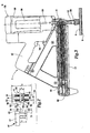
- FIG. 1 is a side view of a magazine follower and a collation strip of fasteners.
- FIG. 2 is an exploded side view of the magazine follower and the collation strip of fasteners.
- FIG. 3 is a partially cut away side view of a fastener driving tool.
- FIG. 4 is a top view of a magazine for the fastener driving tool, with the magazine follower being in a first position.
- FIG. 5 is a top view of the magazine with the magazine follower being in a second position.
- FIG. 6 is a sectional view of the magazine showing the collation strip within a channel of the magazine.
- FIG. 7 is a sectional view of a nosepiece of a fastener driving tool showing an opening for feeding the collation strip to the nosepiece.
- Too12 includes a novel and inventive magazine follower 10 for biasing a collation strip 20 of fasteners 8 through a magazine 12 of too12. Magazine follower 10 creates a force against collation strip 20 to push collation strip 20 of fasteners 8 along magazine 12 to feed fasteners 8 into a barrel 14 of too12 before driving fasteners with a piston driving rod 16. Magazine follower 10 also includes a novel profile 22, which corresponds to a profile 24 of collation strip 20. The matching profiles of magazine follower 10 and collation strip 20 provide greater stability of collation strip 20 within magazine 12.
- Too12 includes a chassis 26 having a housing 28 for enclosing a piston (not shown) having a piston driving rod 16.
- Chassis 26 is generally cylindrical in shape and has a central axis 30 running through the length of too12.
- Too12 uses a power source for creating a driving force to drive the piston in the driving direction. Examples of power sources include pneumatic power using compressed air to drive the piston, gasoline combustion powered using ignited gasoline, and powder actuated tools using explosive powder to drive the piston.
- a handle 32 radially extends away from chassis 26 and includes a trigger 34 for actuating too 12.
- a nosepiece 36 coupled to housing 28 and axially extending away from housing 28 in the driving direction.
- the piston, driving rod 16 and nosepiece 36 are also generally cylindrical in shape having the same central axis 30 as chassis 26.
- Nosepiece 36 includes a barrel 14 axially extending through the length of nosepiece 36 for accepting fasteners 8 and for guiding driving rod 16, also known as a driver blade, of the piston toward impact with fastener 8.
- a magazine 12 for feeding collation strip 20 is connected to nosepiece 36 and extends radially away from nosepiece 36. Magazine 12 includes a channel38 for guiding collation strip 20 along the length of magazine 12 toward nosepiece 36.
- Tool 2 provides for attachment of a substrate 4 to a support member 6 using fasteners 8.
- Substrate 4 could be one of several construction materials commonly attached to support structures of a building, an example being sheathing such as sheet rock and gypsum board, particle board, or plywood.
- Support member 6 could be one of several support structures used in the construction industry, including wooden support studs or thin to medium gauge steel framing studs.
- Collation strip 20 is placed within channel 38 of magazine to feed collation strip of fasteners 8 to nosepiece 36.
- a spring biased magazine follower 10 is included for biasing collation strip 20 along channel38 towards nosepiece 36.
- Magazine follower 10 includes a holder 40 and an engagement portion 42 having a leading end 44 with a profile 22 at leading end 44. Magazine follower 10 is biased towards nosepiece 36 by a spring (not shown) placed between magazine follower 10 and nosepiece 36 to pull magazine follower 10 along magazine 12. The spring provides a generally constant force against magazine follower 10 to bias collation strip 20 along channel 3 8. After a fastener 8 has been driven by too12, there is a vacant space in barrel 14.
- the spring pulls magazine follower 10, which in turn biases collation strip 20 so that the next sleeve 46 and fastener 8 are pushed into the vacancy in barrel 14 so that the next fastener 8 can be driven by tool 2.
- An example of a spring used to pull magazine follower 10 is a constant force spring made from 301 stainless steel having a thickness of about 2,5 mm, a width of about 2,5 mm and a length of about 400 mm, wherein the spring can provide generally constant force acting on magazine follower 10 of about 1 kg force.
- collation strip 20 includes a plurality of sleeves 46 for holding a plurality of fasteners.
- Sleeves 46 are connected in a row along a collation plane with at least one frangible bridge 48 between adjacent sleeves 46.
- Each sleeve 46 includes a body 50 that receives and surrounds an associated fastener 8 in order to hold associated fastener 8 in a predetermined orientation.
- collation strip 20 is formed by injection molding, and fasteners 8 are inserted into each sleeve 46.
- each sleeve 46 of collation strip 20 is designed so that it will split apart into two large pieces so that no portion of sleeve 46 will become trapped between head 52 of fastener 8 and substrate 4.
- An exemplary fastener 8, shown in FIGS. 1 and 2 includes a head 52, a point 54, and a shank 56 axially extending between head 52 and point 54.
- fastener 8 includes knurling 58 along the length of shank 56. Knurling 58 allows for higher pullout strength so that fastener 8 can provide better attachment between substrate 4 and support member 6.
- Shank 56 expands radially outward at head 52 in what is commonly referred to as a bugle configuration.
- a bugle head 52 such as the one shown in FIG. 1 also provides for higher pullout strength and prevents tearing of substrate 4 when fastener 8 is driven.
- Point 54 is preferably generally conical in shape except for a slightly rounded off tip. . Examples of preferred fasteners 8 are disclosed in the U. S. Patents 5,741,104 and 5,749,692
- extension 62 which extends away from end sleeve 46 along the collation plane.
- Extension 62 bas a profile 24 unique to end sleeve 46.
- Profile 22 of magazine follower 10 is complementary to profile 24 of extension 62 except that profile 22 of magazine follower 10 bas a generally concave configuration, as if magazine follower profile 22 had been cut out of engagement portion 42, whereas profile 24 of collation strip 20 has a generally convex configuration so that profile 24 extends away from end sleeve 46 so that extension 62 can be nested within profile 22 of magazine follower 10, stabilizing collation strip 20 and biasing it straight along magazine 12.
- Complementary profiles 22 and 24 ensure that magazine follower 10 supports and stabilizes collation strip 20 while pushing collation strip 20 along magazine channel38, preventing collation strip 20 from bending or "jacking," as described above.
- Magazine follower 10 includes engagement portion 42 having profile 22, described below, and a holder 40, which support engagement portion 42 and provides guidance for magazine follower 10. Magazine follower 10 is laterally mounted to magazine 12, as shown in FIGS. 4 and 5, so that magazine follower 10 is slidable with respect to magazine 12. Holder 40 includes a guiding extension 100 that corresponds to a guide rail (not shown) along magazine 12. Engagement portion 42 is coupled to holder 40 by a pivot pin 64, so that leading end 44 of engagement portion 42 can be pivoted from a first position with profile 22 outside of magazine 12, as shown in FIG. 5, to a second position where profile 22 is inside magazine channel 38, as shown in FIG. 4. Engagement portion 42 has an angled cross section, as shown in FIGS. 4 and 5, to accommodate this pivoting.
- engagement portion 42 includes a pivot leg 66 coupled to holder 40 by pin 64, two angled legs 68 and 70 and a profile leg 72 on which profile 22 is located.
- Angled legs 68 and 70 orient profile leg 72 so that it is properly aligned along magazine channel38, preferably so that profile leg 72 is essentially parallel to channel 38. Without proper orientation of profile leg 72, profile 22 would not bias collation strip 20 properly along magazine 12.
- Angled legs 68 and 70 are generally convex with respect to magazine 12, with an angle 0 between leg 68 and leg 70 of between about 90° and about 110°, and preferably about 100°.
- Profile leg is also slightly angled with respect to leg 70 so that profile leg 72 is aligned generally parallel with magazine channel 3 8.
- Engagement portion 42 of magazine follower 10 should be made out of a material that is strong enough to withstand the forces between the spring and collation strip 20 and should be substantially rigid to adequately support collation strip 20.
- a preferred material of construction of engagement portion 42 is SAE 8620 cast alloy steel hardened and tempered to a hardness of about 30 to about 40 Rockwell C, where the shape of engagement portion 42, particularly profile 22, is produced by investment casting.
- Holder 40 should also be made out of a resilient material, but does not have to be as rigid as engagement portion 42.
- An example of a suitable material of construction for holder 40 is also SAE 8620 cast alloy steel hardened and tempered to a hardness of about 30 to about 40 Rockwell C.
- Engagement portion 42 and holder 40 can also be plated to avoid corrosion. Preferred plating is electroless nickel having a thickness of between about 0.0076 mm and about 0,0127 mm.
- magazine 12 guides collation strip 20 along channel38 so that each sleeve 46 that is fed into barrel 14 of nosepiece 36 is fed in a proper orientation.
- a cross section of channel 38 includes a unique shape that corresponds to the cross section of collation strip 20 and fasteners 8.
- Channel 38 includes several guiding surfaces, such as head guide 74 and sleeve guides 76 and 78 which keep fasteners 8 in the desired orientation.
- Each sleeve 46 and fastener 8 fit within channel38 within a predetermined tolerance.
- Collation strip 20 is fed into trailing end 80 of magazine 12 through a feed opening (not shown).
- Magazine follower 10 is set at the first position so that engagement portion 42 is outside of magazine channel38 to allow collation strip 20 to be pushed past magazine follower 10 toward nosepiece 36. Engagement portion 42 is then pivoted from the first position to the second position, so that magazine follower profile 22 is within channel38 so that it can engage with collation strip 20.
- profile 24 of extension 62 of collation strip 20 is generally rectangular in shape having an upper surface 82, a side surface 84, and a lower surface 86.
- the length 1 of side surface 84 is the same as the length of each sleeve 46 of collation strip 20.
- Magazine follower profile 22 is also generally rectangular in shape and complements profile 24 of extension 62. Magazine follower profile 22 has a top surface 88, a side surface 90, and a bottom surface 92 corresponding to the upper surface 82, side surface 84, and lower surface 86, respectively, of extension 62.
- the length L of magazine follower profile 22 is slightly larger than the length 1 of collation strip profile 24 so that extension 62 of collation strip will fit within magazine follower 10 within a predetermined tolerance.
- Engagement portion 42 of magazine follower 10 should have a total length LT that is shorter than the length LF of fastener 8.
- the clearance C between leading surface 94 of engagement portion 42 and an outer surface 96 of fastener shank 56 is preferred to be as close as possible, therefore the depth D of magazine follower profile 22 is chosen so that magazine follower 10 is close to fastener shank 56 within a predetermined tolerance.
- a close clearance C allows engagement portion 42 to support shank 56 and correct the alignment of fastener 8 if it becomes misaligned.
- the width W of engagement portion 42 is also slightly larger than the width w of extension 62 to ensure lateral stability of collation strip 20.
- the length LF of fastener 8 is about 2,54 cm, while the length 1 of extension 62 of collation strip 20 is about 0.864 cm.
- the total length L T of engagement portion 42 is about 2,11 cm and the length L of engagement portion profile 22 is about 1,08 cm.
- a total tolerance between top surface 88 of magazine follower profile 22 and upper surface 82 of extension 62 and between bottom surface 92 of magazine follower profile 22 and lower surface 86 of extension 62 is about 2 mm.
- the depth D of magazine follower profile 22 is about 2,54 mm
- the depth d of extension 62 from outer surface 96 of shank 56 to side surface 84 of extension 62 is about 3,05 mm
- the clearance C between outer surface 96 of shank 56 and leading surface 94 of engagement portion 42 is about 0,5 mm
- the width W of engagement portion 42 is about 3,81 mm and the width w of extension 62 is about 3,05 mm.
- Magazine follower 10 and collation strip 20 could have alternative profiles.
- the geometric shape of magazine follower profile 22 and collation strip profile 24 should complement each other, and the supporting surfaces of magazine follower 10 are important to prevent bending or jacking of collation strip 20.
- opening 98 in nosepiece 36 is included so that each sleeve 46 will be fed through nosepiece 36 into barrel 14 in the proper orientation. Opening 98 is shaped so that sleeve 46 and fastener 8 can only fit through in one orientation, so that if either sleeve 46 or fastener 8 is improperly aligned, sleeve 46 will not fit through opening 98. When sleeve 46 and fastener 8 are properly aligned they can pass through opening 98 into a barrel 14 in nosepiece 36.
- Nosepiece 36 is connected to tool 2 so that it can be in an extended position and a retracted position relative to tool 2. Nosepiece 36 is biased toward the extended position and too12 is designed so that it cannot be actuated unless nosepiece 36 is in the retracted position so that too 12 cannot be fired unless nosepiece 36 is pushed against substrate 4.
- a fastener support (not shown) is also pushed upwards until the fastener support engages with fastener point 54, where it supports fastener 8 in a predetermined position.
- tool 2 can be actuated, driving the piston in the driving direction until the piston eventually hits fastener head 52 and begins to drive fastener 8 and sleeve 46 in the driving direction.
- a shearing member (not shown) is also included in too12 that cleanly shears sleeve 46 from the rest of collation strip 20 as fastener 8 and sleeve 46 are driven into substrate 4. After too12 is actuated, fastener 8 is driven into substrate 4, and sleeve 46 breaks away from fastener 8.
- the present invention provides an improved and novel magazine follower having a unique, complementary profile to the unique profile of the collation strip being biased by the magazine follower.
- the matching profiles allow the magazine follower to support the collation strip, and prevent it from bending, breaking or jacking within the magazine of the fastener driving tool.
Landscapes
- Engineering & Computer Science (AREA)
- Mechanical Engineering (AREA)
- General Engineering & Computer Science (AREA)
- Chemical & Material Sciences (AREA)
- Combustion & Propulsion (AREA)
- Portable Nailing Machines And Staplers (AREA)
Applications Claiming Priority (2)
| Application Number | Priority Date | Filing Date | Title |
|---|---|---|---|
| US10/223,517 US6679412B1 (en) | 2002-08-19 | 2002-08-19 | Stabilizing magazine follower for fastener driving tool |
| US223517 | 2002-08-19 |
Publications (2)
| Publication Number | Publication Date |
|---|---|
| EP1391268A2 true EP1391268A2 (fr) | 2004-02-25 |
| EP1391268A3 EP1391268A3 (fr) | 2008-11-12 |
Family
ID=30000168
Family Applications (1)
| Application Number | Title | Priority Date | Filing Date |
|---|---|---|---|
| EP03292045A Withdrawn EP1391268A3 (fr) | 2002-08-19 | 2003-08-19 | Outil pour moyens de fixation avec gâchette pour magazine |
Country Status (5)
| Country | Link |
|---|---|
| US (1) | US6679412B1 (fr) |
| EP (1) | EP1391268A3 (fr) |
| JP (1) | JP2004074403A (fr) |
| AU (1) | AU2003231723B2 (fr) |
| CA (1) | CA2437174C (fr) |
Families Citing this family (14)
| Publication number | Priority date | Publication date | Assignee | Title |
|---|---|---|---|---|
| US6708821B2 (en) * | 2002-08-21 | 2004-03-23 | Illinois Tool Works Inc. | Fastener collation strip and debris exhaust mechanism |
| FR2850895B1 (fr) * | 2003-02-10 | 2006-03-03 | Prospection & Inventions | Bande d'elements de fixation pour appareil de scellement avec chargeur destine a recevoir la bande, l'appareil et le chargeur |
| US6986450B2 (en) * | 2003-04-30 | 2006-01-17 | Henrob Limited | Fastener insertion apparatus |
| JP4580680B2 (ja) * | 2004-04-30 | 2010-11-17 | 日本パワーファスニング株式会社 | ファスナー打ち込み工具用マガジン |
| US7971768B2 (en) * | 2004-05-04 | 2011-07-05 | Illinois Tool Works Inc. | Guidance system for fasteners |
| JP4877463B2 (ja) * | 2005-07-13 | 2012-02-15 | マックス株式会社 | ファスナー打ち込み工具のファスナー送り機構 |
| JP2011200992A (ja) * | 2010-03-26 | 2011-10-13 | Makita Corp | 打ち込み工具のマガジン |
| JP5701658B2 (ja) * | 2011-03-31 | 2015-04-15 | 株式会社マキタ | 打ち込み工具 |
| FR2993810B1 (fr) * | 2012-07-25 | 2014-07-11 | Illinois Tool Works | Outil de fixation par tir indirect, a support de detente anti-tir |
| US9573260B2 (en) * | 2013-05-08 | 2017-02-21 | Arthur R. Walters, JR. | Fastening device for driving double-headed fasteners |
| TWI458605B (zh) * | 2013-08-09 | 2014-11-01 | Basso Ind Corp | A nail device for a nail gun |
| EP3501746A1 (fr) * | 2017-12-21 | 2019-06-26 | HILTI Aktiengesellschaft | Dispositif d'enfoncement |
| US10828754B2 (en) | 2018-09-24 | 2020-11-10 | Raytheon Company | Fastener dispenser and presentation via removable magazine |
| AU2021232748A1 (en) * | 2021-08-25 | 2023-04-06 | Illinois Tool Works Inc. | Fastener Pin |
Citations (4)
| Publication number | Priority date | Publication date | Assignee | Title |
|---|---|---|---|---|
| DE19602789A1 (de) * | 1996-01-26 | 1997-07-31 | Hilti Ag | Nagelstreifen für Setzgerät |
| EP0893205A1 (fr) * | 1997-07-25 | 1999-01-27 | Societe De Prospection Et D'inventions Techniques Spit | Bande de bagues de réception de tampon de scellement pour appareil de scellement de tampon |
| EP0908635A1 (fr) * | 1997-10-07 | 1999-04-14 | Illinois Tool Works Inc. | Dispositif d'attache à prolongement latéral |
| EP0987086A2 (fr) * | 1998-09-18 | 2000-03-22 | Ramset Fasteners (Aust.) Pty. Ltd. | Outils motorisés comportant un mécanisme d'alimentation du type à chargeur |
Family Cites Families (8)
| Publication number | Priority date | Publication date | Assignee | Title |
|---|---|---|---|---|
| DE3606901A1 (de) * | 1986-03-03 | 1987-09-10 | Hilti Ag | Nagelstreifen |
| US5813588A (en) * | 1996-10-09 | 1998-09-29 | Lin; George | Magazine assembly for fastener driving tools |
| US6629360B2 (en) * | 1998-04-16 | 2003-10-07 | Opt Engineering Company Limited | Continuous riveter |
| US6012622A (en) | 1998-04-20 | 2000-01-11 | Illinois Tool Works Inc. | Fastener driving tool for trim applications |
| US6431430B1 (en) * | 1998-09-18 | 2002-08-13 | Stanley Fastening Systems, L.P. | Battery operated roofing nailer and nails therefor |
| US6499642B1 (en) * | 1999-03-04 | 2002-12-31 | Max Co., Ltd. | Magazine mechanism for nailing machine |
| US6592014B2 (en) * | 2001-12-13 | 2003-07-15 | Illinois Tool Works Inc. | Lockout mechanism for fastener driving tool |
| US6612476B2 (en) * | 2002-01-14 | 2003-09-02 | Illinois Tool Works Inc. | Fastener driving tool with modular construction |
-
2002
- 2002-08-19 US US10/223,517 patent/US6679412B1/en not_active Expired - Fee Related
-
2003
- 2003-08-12 AU AU2003231723A patent/AU2003231723B2/en not_active Ceased
- 2003-08-13 CA CA002437174A patent/CA2437174C/fr not_active Expired - Fee Related
- 2003-08-14 JP JP2003293410A patent/JP2004074403A/ja active Pending
- 2003-08-19 EP EP03292045A patent/EP1391268A3/fr not_active Withdrawn
Patent Citations (4)
| Publication number | Priority date | Publication date | Assignee | Title |
|---|---|---|---|---|
| DE19602789A1 (de) * | 1996-01-26 | 1997-07-31 | Hilti Ag | Nagelstreifen für Setzgerät |
| EP0893205A1 (fr) * | 1997-07-25 | 1999-01-27 | Societe De Prospection Et D'inventions Techniques Spit | Bande de bagues de réception de tampon de scellement pour appareil de scellement de tampon |
| EP0908635A1 (fr) * | 1997-10-07 | 1999-04-14 | Illinois Tool Works Inc. | Dispositif d'attache à prolongement latéral |
| EP0987086A2 (fr) * | 1998-09-18 | 2000-03-22 | Ramset Fasteners (Aust.) Pty. Ltd. | Outils motorisés comportant un mécanisme d'alimentation du type à chargeur |
Also Published As
| Publication number | Publication date |
|---|---|
| JP2004074403A (ja) | 2004-03-11 |
| US6679412B1 (en) | 2004-01-20 |
| CA2437174A1 (fr) | 2004-02-19 |
| AU2003231723B2 (en) | 2006-02-02 |
| CA2437174C (fr) | 2008-03-18 |
| EP1391268A3 (fr) | 2008-11-12 |
| AU2003231723A1 (en) | 2004-03-11 |
Similar Documents
| Publication | Publication Date | Title |
|---|---|---|
| AU2005237853B2 (en) | Guidance system for fasteners | |
| US6679412B1 (en) | Stabilizing magazine follower for fastener driving tool | |
| AU2003231725B2 (en) | Fastener collation strip and debris exhaust mechanism | |
| US5069340A (en) | Strip of collated fasteners for fastener-driving tool | |
| US8893943B2 (en) | Collations for fasteners of various lengths | |
| JP4243503B2 (ja) | 固定具打ち込み工具のマガジン | |
| US20050050712A1 (en) | Fastener driving tool for spacing object from substrate | |
| US6568302B2 (en) | Telescoping support device for fastener driving tool | |
| US20040182908A1 (en) | Power tool for metal piercing fasteners | |
| US20230311286A1 (en) | Nail driving tool, in particular compressed air nailer, movable guide element, stationary guide element, kit, and base for such a kit, and system and retrofitting system | |
| NZ529189A (en) | Fastener collation strip and debris exhaust mechanism |
Legal Events
| Date | Code | Title | Description |
|---|---|---|---|
| PUAI | Public reference made under article 153(3) epc to a published international application that has entered the european phase |
Free format text: ORIGINAL CODE: 0009012 |
|
| AK | Designated contracting states |
Kind code of ref document: A2 Designated state(s): AT BE BG CH CY CZ DE DK EE ES FI FR GB GR HU IE IT LI LU MC NL PT RO SE SI SK TR |
|
| AX | Request for extension of the european patent |
Extension state: AL LT LV MK |
|
| PUAL | Search report despatched |
Free format text: ORIGINAL CODE: 0009013 |
|
| AK | Designated contracting states |
Kind code of ref document: A3 Designated state(s): AT BE BG CH CY CZ DE DK EE ES FI FR GB GR HU IE IT LI LU MC NL PT RO SE SI SK TR |
|
| AX | Request for extension of the european patent |
Extension state: AL LT LV MK |
|
| 17P | Request for examination filed |
Effective date: 20090506 |
|
| AKX | Designation fees paid |
Designated state(s): BE DE FR GB NL |
|
| 17Q | First examination report despatched |
Effective date: 20101011 |
|
| RAP1 | Party data changed (applicant data changed or rights of an application transferred) |
Owner name: ILLINOIS TOOL WORKS INC. |
|
| STAA | Information on the status of an ep patent application or granted ep patent |
Free format text: STATUS: THE APPLICATION IS DEEMED TO BE WITHDRAWN |
|
| 18D | Application deemed to be withdrawn |
Effective date: 20150303 |