EP1390450B1 - Catalyst composition and method for oxidizing mixtures - Google Patents
Catalyst composition and method for oxidizing mixtures Download PDFInfo
- Publication number
- EP1390450B1 EP1390450B1 EP02723320A EP02723320A EP1390450B1 EP 1390450 B1 EP1390450 B1 EP 1390450B1 EP 02723320 A EP02723320 A EP 02723320A EP 02723320 A EP02723320 A EP 02723320A EP 1390450 B1 EP1390450 B1 EP 1390450B1
- Authority
- EP
- European Patent Office
- Prior art keywords
- fuel
- catalyst mixture
- catalyst
- oxidizing
- group
- Prior art date
- Legal status (The legal status is an assumption and is not a legal conclusion. Google has not performed a legal analysis and makes no representation as to the accuracy of the status listed.)
- Expired - Lifetime
Links
- 239000003054 catalyst Substances 0.000 title claims abstract description 248
- 239000000203 mixture Substances 0.000 title claims abstract description 151
- 238000000034 method Methods 0.000 title claims abstract description 58
- 230000001590 oxidative effect Effects 0.000 title claims abstract description 31
- 239000000446 fuel Substances 0.000 claims abstract description 93
- 230000003647 oxidation Effects 0.000 claims abstract description 49
- 238000007254 oxidation reaction Methods 0.000 claims abstract description 49
- 238000002156 mixing Methods 0.000 claims abstract description 14
- 229930195733 hydrocarbon Natural products 0.000 claims abstract description 9
- 150000002430 hydrocarbons Chemical class 0.000 claims abstract description 9
- 239000004215 Carbon black (E152) Substances 0.000 claims abstract description 8
- 238000002485 combustion reaction Methods 0.000 claims description 50
- 239000002245 particle Substances 0.000 claims description 50
- 239000007789 gas Substances 0.000 claims description 42
- LYCAIKOWRPUZTN-UHFFFAOYSA-N Ethylene glycol Chemical compound OCCO LYCAIKOWRPUZTN-UHFFFAOYSA-N 0.000 claims description 21
- OKKJLVBELUTLKV-UHFFFAOYSA-N Methanol Chemical compound OC OKKJLVBELUTLKV-UHFFFAOYSA-N 0.000 claims description 21
- 239000007788 liquid Substances 0.000 claims description 18
- LFQSCWFLJHTTHZ-UHFFFAOYSA-N Ethanol Chemical compound CCO LFQSCWFLJHTTHZ-UHFFFAOYSA-N 0.000 claims description 17
- VNWKTOKETHGBQD-UHFFFAOYSA-N methane Chemical compound C VNWKTOKETHGBQD-UHFFFAOYSA-N 0.000 claims description 17
- XLYOFNOQVPJJNP-UHFFFAOYSA-N water Substances O XLYOFNOQVPJJNP-UHFFFAOYSA-N 0.000 claims description 17
- UHOVQNZJYSORNB-UHFFFAOYSA-N Benzene Chemical compound C1=CC=CC=C1 UHOVQNZJYSORNB-UHFFFAOYSA-N 0.000 claims description 15
- YXFVVABEGXRONW-UHFFFAOYSA-N Toluene Chemical compound CC1=CC=CC=C1 YXFVVABEGXRONW-UHFFFAOYSA-N 0.000 claims description 15
- LRHPLDYGYMQRHN-UHFFFAOYSA-N N-Butanol Chemical compound CCCCO LRHPLDYGYMQRHN-UHFFFAOYSA-N 0.000 claims description 14
- AMQJEAYHLZJPGS-UHFFFAOYSA-N N-Pentanol Chemical compound CCCCCO AMQJEAYHLZJPGS-UHFFFAOYSA-N 0.000 claims description 14
- VSCWAEJMTAWNJL-UHFFFAOYSA-K aluminium trichloride Chemical compound Cl[Al](Cl)Cl VSCWAEJMTAWNJL-UHFFFAOYSA-K 0.000 claims description 14
- ZSIAUFGUXNUGDI-UHFFFAOYSA-N hexan-1-ol Chemical compound CCCCCCO ZSIAUFGUXNUGDI-UHFFFAOYSA-N 0.000 claims description 14
- ZXEKIIBDNHEJCQ-UHFFFAOYSA-N isobutanol Chemical compound CC(C)CO ZXEKIIBDNHEJCQ-UHFFFAOYSA-N 0.000 claims description 14
- 239000003502 gasoline Substances 0.000 claims description 13
- KFZMGEQAYNKOFK-UHFFFAOYSA-N Isopropanol Chemical compound CC(C)O KFZMGEQAYNKOFK-UHFFFAOYSA-N 0.000 claims description 12
- KBPLFHHGFOOTCA-UHFFFAOYSA-N 1-Octanol Chemical compound CCCCCCCCO KBPLFHHGFOOTCA-UHFFFAOYSA-N 0.000 claims description 10
- BBMCTIGTTCKYKF-UHFFFAOYSA-N 1-heptanol Chemical compound CCCCCCCO BBMCTIGTTCKYKF-UHFFFAOYSA-N 0.000 claims description 10
- ATUOYWHBWRKTHZ-UHFFFAOYSA-N Propane Chemical compound CCC ATUOYWHBWRKTHZ-UHFFFAOYSA-N 0.000 claims description 10
- NNPPMTNAJDCUHE-UHFFFAOYSA-N isobutane Chemical compound CC(C)C NNPPMTNAJDCUHE-UHFFFAOYSA-N 0.000 claims description 10
- 239000002283 diesel fuel Substances 0.000 claims description 9
- KWGKDLIKAYFUFQ-UHFFFAOYSA-M lithium chloride Chemical compound [Li+].[Cl-] KWGKDLIKAYFUFQ-UHFFFAOYSA-M 0.000 claims description 9
- BDERNNFJNOPAEC-UHFFFAOYSA-N propan-1-ol Chemical compound CCCO BDERNNFJNOPAEC-UHFFFAOYSA-N 0.000 claims description 7
- 239000004094 surface-active agent Substances 0.000 claims description 7
- XKRFYHLGVUSROY-UHFFFAOYSA-N Argon Chemical compound [Ar] XKRFYHLGVUSROY-UHFFFAOYSA-N 0.000 claims description 6
- IJGRMHOSHXDMSA-UHFFFAOYSA-N Atomic nitrogen Chemical compound N#N IJGRMHOSHXDMSA-UHFFFAOYSA-N 0.000 claims description 6
- VEXZGXHMUGYJMC-UHFFFAOYSA-N Hydrochloric acid Chemical compound Cl VEXZGXHMUGYJMC-UHFFFAOYSA-N 0.000 claims description 6
- DNIAPMSPPWPWGF-UHFFFAOYSA-N Propylene glycol Chemical compound CC(O)CO DNIAPMSPPWPWGF-UHFFFAOYSA-N 0.000 claims description 6
- FAPWRFPIFSIZLT-UHFFFAOYSA-M Sodium chloride Chemical compound [Na+].[Cl-] FAPWRFPIFSIZLT-UHFFFAOYSA-M 0.000 claims description 6
- OTMSDBZUPAUEDD-UHFFFAOYSA-N Ethane Chemical compound CC OTMSDBZUPAUEDD-UHFFFAOYSA-N 0.000 claims description 5
- CTQNGGLPUBDAKN-UHFFFAOYSA-N O-Xylene Chemical compound CC1=CC=CC=C1C CTQNGGLPUBDAKN-UHFFFAOYSA-N 0.000 claims description 5
- 229910021604 Rhodium(III) chloride Inorganic materials 0.000 claims description 5
- 150000001298 alcohols Chemical class 0.000 claims description 5
- 239000010426 asphalt Substances 0.000 claims description 5
- 239000001273 butane Substances 0.000 claims description 5
- 125000004432 carbon atom Chemical group C* 0.000 claims description 5
- 238000001311 chemical methods and process Methods 0.000 claims description 5
- 239000003245 coal Substances 0.000 claims description 5
- 239000003034 coal gas Substances 0.000 claims description 5
- 239000002285 corn oil Substances 0.000 claims description 5
- 235000005687 corn oil Nutrition 0.000 claims description 5
- 239000010779 crude oil Substances 0.000 claims description 5
- 239000000295 fuel oil Substances 0.000 claims description 5
- 239000001282 iso-butane Substances 0.000 claims description 5
- 239000002480 mineral oil Substances 0.000 claims description 5
- 235000010446 mineral oil Nutrition 0.000 claims description 5
- IJDNQMDRQITEOD-UHFFFAOYSA-N n-butane Chemical compound CCCC IJDNQMDRQITEOD-UHFFFAOYSA-N 0.000 claims description 5
- OFBQJSOFQDEBGM-UHFFFAOYSA-N n-pentane Natural products CCCCC OFBQJSOFQDEBGM-UHFFFAOYSA-N 0.000 claims description 5
- 239000010743 number 2 fuel oil Substances 0.000 claims description 5
- TVMXDCGIABBOFY-UHFFFAOYSA-N octane Chemical compound CCCCCCCC TVMXDCGIABBOFY-UHFFFAOYSA-N 0.000 claims description 5
- 239000001294 propane Substances 0.000 claims description 5
- SONJTKJMTWTJCT-UHFFFAOYSA-K rhodium(iii) chloride Chemical compound [Cl-].[Cl-].[Cl-].[Rh+3] SONJTKJMTWTJCT-UHFFFAOYSA-K 0.000 claims description 5
- 235000015112 vegetable and seed oil Nutrition 0.000 claims description 5
- 239000008158 vegetable oil Substances 0.000 claims description 5
- 239000002023 wood Substances 0.000 claims description 5
- 239000008096 xylene Substances 0.000 claims description 5
- 229910004664 Cerium(III) chloride Inorganic materials 0.000 claims description 4
- VYLVYHXQOHJDJL-UHFFFAOYSA-K cerium trichloride Chemical compound Cl[Ce](Cl)Cl VYLVYHXQOHJDJL-UHFFFAOYSA-K 0.000 claims description 4
- 239000003570 air Substances 0.000 claims description 3
- 229910052786 argon Inorganic materials 0.000 claims description 3
- KTWOOEGAPBSYNW-UHFFFAOYSA-N ferrocene Chemical compound [Fe+2].C=1C=C[CH-]C=1.C=1C=C[CH-]C=1 KTWOOEGAPBSYNW-UHFFFAOYSA-N 0.000 claims description 3
- 239000001307 helium Substances 0.000 claims description 3
- 229910052734 helium Inorganic materials 0.000 claims description 3
- SWQJXJOGLNCZEY-UHFFFAOYSA-N helium atom Chemical compound [He] SWQJXJOGLNCZEY-UHFFFAOYSA-N 0.000 claims description 3
- 229910052757 nitrogen Inorganic materials 0.000 claims description 3
- 239000011780 sodium chloride Substances 0.000 claims description 3
- 229910052684 Cerium Inorganic materials 0.000 claims description 2
- GWXLDORMOJMVQZ-UHFFFAOYSA-N cerium Chemical compound [Ce] GWXLDORMOJMVQZ-UHFFFAOYSA-N 0.000 claims description 2
- 229940035429 isobutyl alcohol Drugs 0.000 claims description 2
- 229920002545 silicone oil Polymers 0.000 claims description 2
- 229910002621 H2PtCl6 Inorganic materials 0.000 claims 2
- XEEYBQQBJWHFJM-UHFFFAOYSA-N Iron Chemical compound [Fe] XEEYBQQBJWHFJM-UHFFFAOYSA-N 0.000 claims 2
- 239000011260 aqueous acid Substances 0.000 claims 2
- 229910052742 iron Inorganic materials 0.000 claims 1
- BASFCYQUMIYNBI-UHFFFAOYSA-N platinum Chemical compound [Pt] BASFCYQUMIYNBI-UHFFFAOYSA-N 0.000 abstract description 30
- 230000008569 process Effects 0.000 abstract description 26
- 150000001875 compounds Chemical class 0.000 abstract description 15
- 229910052697 platinum Inorganic materials 0.000 abstract description 15
- 229910052782 aluminium Inorganic materials 0.000 abstract description 14
- XAGFODPZIPBFFR-UHFFFAOYSA-N aluminium Chemical compound [Al] XAGFODPZIPBFFR-UHFFFAOYSA-N 0.000 abstract description 14
- 229910052703 rhodium Inorganic materials 0.000 abstract description 7
- 239000010948 rhodium Substances 0.000 abstract description 7
- MHOVAHRLVXNVSD-UHFFFAOYSA-N rhodium atom Chemical compound [Rh] MHOVAHRLVXNVSD-UHFFFAOYSA-N 0.000 abstract description 7
- 230000001965 increasing effect Effects 0.000 abstract description 5
- 229910052702 rhenium Inorganic materials 0.000 abstract description 5
- WUAPFZMCVAUBPE-UHFFFAOYSA-N rhenium atom Chemical compound [Re] WUAPFZMCVAUBPE-UHFFFAOYSA-N 0.000 abstract description 5
- 150000002602 lanthanoids Chemical class 0.000 abstract description 4
- 229910052747 lanthanoid Inorganic materials 0.000 abstract description 2
- FYYHWMGAXLPEAU-UHFFFAOYSA-N Magnesium Chemical compound [Mg] FYYHWMGAXLPEAU-UHFFFAOYSA-N 0.000 abstract 1
- 229910052792 caesium Inorganic materials 0.000 abstract 1
- TVFDJXOCXUVLDH-UHFFFAOYSA-N caesium atom Chemical compound [Cs] TVFDJXOCXUVLDH-UHFFFAOYSA-N 0.000 abstract 1
- 229910052749 magnesium Inorganic materials 0.000 abstract 1
- 239000011777 magnesium Substances 0.000 abstract 1
- 239000002594 sorbent Substances 0.000 description 19
- 150000002500 ions Chemical class 0.000 description 10
- 238000005054 agglomeration Methods 0.000 description 8
- 230000002776 aggregation Effects 0.000 description 8
- 230000009467 reduction Effects 0.000 description 8
- 230000008901 benefit Effects 0.000 description 7
- 239000000463 material Substances 0.000 description 6
- 239000007798 antifreeze agent Substances 0.000 description 5
- 230000003197 catalytic effect Effects 0.000 description 5
- UGFAIRIUMAVXCW-UHFFFAOYSA-N Carbon monoxide Chemical compound [O+]#[C-] UGFAIRIUMAVXCW-UHFFFAOYSA-N 0.000 description 3
- 229910003594 H2PtCl6.6H2O Inorganic materials 0.000 description 3
- PNEYBMLMFCGWSK-UHFFFAOYSA-N aluminium oxide Inorganic materials [O-2].[O-2].[O-2].[Al+3].[Al+3] PNEYBMLMFCGWSK-UHFFFAOYSA-N 0.000 description 3
- 239000000872 buffer Substances 0.000 description 3
- 229910002091 carbon monoxide Inorganic materials 0.000 description 3
- CETPSERCERDGAM-UHFFFAOYSA-N ceric oxide Chemical compound O=[Ce]=O CETPSERCERDGAM-UHFFFAOYSA-N 0.000 description 3
- HSJPMRKMPBAUAU-UHFFFAOYSA-N cerium nitrate Inorganic materials [Ce+3].[O-][N+]([O-])=O.[O-][N+]([O-])=O.[O-][N+]([O-])=O HSJPMRKMPBAUAU-UHFFFAOYSA-N 0.000 description 3
- 229910000422 cerium(IV) oxide Inorganic materials 0.000 description 3
- 230000008859 change Effects 0.000 description 3
- 238000002347 injection Methods 0.000 description 3
- 239000007924 injection Substances 0.000 description 3
- 239000002243 precursor Substances 0.000 description 3
- 239000000243 solution Substances 0.000 description 3
- 239000000126 substance Substances 0.000 description 3
- 229910052815 sulfur oxide Inorganic materials 0.000 description 3
- QSHYGLAZPRJAEZ-UHFFFAOYSA-N 4-(chloromethyl)-2-(2-methylphenyl)-1,3-thiazole Chemical compound CC1=CC=CC=C1C1=NC(CCl)=CS1 QSHYGLAZPRJAEZ-UHFFFAOYSA-N 0.000 description 2
- ZAMOUSCENKQFHK-UHFFFAOYSA-N Chlorine atom Chemical compound [Cl] ZAMOUSCENKQFHK-UHFFFAOYSA-N 0.000 description 2
- 239000002253 acid Substances 0.000 description 2
- JLDSOYXADOWAKB-UHFFFAOYSA-N aluminium nitrate Chemical compound [Al+3].[O-][N+]([O-])=O.[O-][N+]([O-])=O.[O-][N+]([O-])=O JLDSOYXADOWAKB-UHFFFAOYSA-N 0.000 description 2
- 230000005587 bubbling Effects 0.000 description 2
- 239000000460 chlorine Substances 0.000 description 2
- 229910052801 chlorine Inorganic materials 0.000 description 2
- 239000000567 combustion gas Substances 0.000 description 2
- 230000009969 flowable effect Effects 0.000 description 2
- 239000002816 fuel additive Substances 0.000 description 2
- 239000002828 fuel tank Substances 0.000 description 2
- 238000005259 measurement Methods 0.000 description 2
- 229910052751 metal Inorganic materials 0.000 description 2
- 239000002184 metal Substances 0.000 description 2
- 230000007935 neutral effect Effects 0.000 description 2
- 150000003282 rhenium compounds Chemical class 0.000 description 2
- 230000003068 static effect Effects 0.000 description 2
- OKTJSMMVPCPJKN-UHFFFAOYSA-N Carbon Chemical compound [C] OKTJSMMVPCPJKN-UHFFFAOYSA-N 0.000 description 1
- YASYEJJMZJALEJ-UHFFFAOYSA-N Citric acid monohydrate Chemical compound O.OC(=O)CC(O)(C(O)=O)CC(O)=O YASYEJJMZJALEJ-UHFFFAOYSA-N 0.000 description 1
- 238000003915 air pollution Methods 0.000 description 1
- 239000004411 aluminium Substances 0.000 description 1
- 230000002528 anti-freeze Effects 0.000 description 1
- 239000012298 atmosphere Substances 0.000 description 1
- QVGXLLKOCUKJST-UHFFFAOYSA-N atomic oxygen Chemical compound [O] QVGXLLKOCUKJST-UHFFFAOYSA-N 0.000 description 1
- 230000015572 biosynthetic process Effects 0.000 description 1
- 229910052799 carbon Inorganic materials 0.000 description 1
- 229910000421 cerium(III) oxide Inorganic materials 0.000 description 1
- 229960002303 citric acid monohydrate Drugs 0.000 description 1
- 239000011248 coating agent Substances 0.000 description 1
- 238000000576 coating method Methods 0.000 description 1
- 238000010668 complexation reaction Methods 0.000 description 1
- 239000000356 contaminant Substances 0.000 description 1
- 229910052593 corundum Inorganic materials 0.000 description 1
- 230000007423 decrease Effects 0.000 description 1
- 230000003247 decreasing effect Effects 0.000 description 1
- 239000003599 detergent Substances 0.000 description 1
- 239000012153 distilled water Substances 0.000 description 1
- TXKMVPPZCYKFAC-UHFFFAOYSA-N disulfur monoxide Inorganic materials O=S=S TXKMVPPZCYKFAC-UHFFFAOYSA-N 0.000 description 1
- 239000012530 fluid Substances 0.000 description 1
- 238000005187 foaming Methods 0.000 description 1
- 230000008014 freezing Effects 0.000 description 1
- 238000007710 freezing Methods 0.000 description 1
- 150000002334 glycols Chemical class 0.000 description 1
- 238000005338 heat storage Methods 0.000 description 1
- 238000010438 heat treatment Methods 0.000 description 1
- 230000006698 induction Effects 0.000 description 1
- 230000001939 inductive effect Effects 0.000 description 1
- 239000011261 inert gas Substances 0.000 description 1
- 230000003993 interaction Effects 0.000 description 1
- 239000011159 matrix material Substances 0.000 description 1
- 239000003345 natural gas Substances 0.000 description 1
- 239000006259 organic additive Substances 0.000 description 1
- 239000003960 organic solvent Substances 0.000 description 1
- 239000001301 oxygen Substances 0.000 description 1
- 229910052760 oxygen Inorganic materials 0.000 description 1
- 238000007747 plating Methods 0.000 description 1
- 239000000843 powder Substances 0.000 description 1
- 230000002265 prevention Effects 0.000 description 1
- 238000000926 separation method Methods 0.000 description 1
- 239000007787 solid Substances 0.000 description 1
- 239000011949 solid catalyst Substances 0.000 description 1
- XTQHKBHJIVJGKJ-UHFFFAOYSA-N sulfur monoxide Chemical compound S=O XTQHKBHJIVJGKJ-UHFFFAOYSA-N 0.000 description 1
- 239000000725 suspension Substances 0.000 description 1
- LENZDBCJOHFCAS-UHFFFAOYSA-N tris Chemical compound OCC(N)(CO)CO LENZDBCJOHFCAS-UHFFFAOYSA-N 0.000 description 1
- 239000002699 waste material Substances 0.000 description 1
- 229910001845 yogo sapphire Inorganic materials 0.000 description 1
Images

Classifications
-
- F—MECHANICAL ENGINEERING; LIGHTING; HEATING; WEAPONS; BLASTING
- F02—COMBUSTION ENGINES; HOT-GAS OR COMBUSTION-PRODUCT ENGINE PLANTS
- F02M—SUPPLYING COMBUSTION ENGINES IN GENERAL WITH COMBUSTIBLE MIXTURES OR CONSTITUENTS THEREOF
- F02M27/00—Apparatus for treating combustion-air, fuel, or fuel-air mixture, by catalysts, electric means, magnetism, rays, sound waves, or the like
- F02M27/02—Apparatus for treating combustion-air, fuel, or fuel-air mixture, by catalysts, electric means, magnetism, rays, sound waves, or the like by catalysts
-
- B—PERFORMING OPERATIONS; TRANSPORTING
- B01—PHYSICAL OR CHEMICAL PROCESSES OR APPARATUS IN GENERAL
- B01J—CHEMICAL OR PHYSICAL PROCESSES, e.g. CATALYSIS OR COLLOID CHEMISTRY; THEIR RELEVANT APPARATUS
- B01J23/00—Catalysts comprising metals or metal oxides or hydroxides, not provided for in group B01J21/00
- B01J23/38—Catalysts comprising metals or metal oxides or hydroxides, not provided for in group B01J21/00 of noble metals
- B01J23/54—Catalysts comprising metals or metal oxides or hydroxides, not provided for in group B01J21/00 of noble metals combined with metals, oxides or hydroxides provided for in groups B01J23/02 - B01J23/36
- B01J23/56—Platinum group metals
- B01J23/64—Platinum group metals with arsenic, antimony, bismuth, vanadium, niobium, tantalum, polonium, chromium, molybdenum, tungsten, manganese, technetium or rhenium
- B01J23/656—Manganese, technetium or rhenium
- B01J23/6567—Rhenium
-
- B01J35/27—
-
- C—CHEMISTRY; METALLURGY
- C10—PETROLEUM, GAS OR COKE INDUSTRIES; TECHNICAL GASES CONTAINING CARBON MONOXIDE; FUELS; LUBRICANTS; PEAT
- C10L—FUELS NOT OTHERWISE PROVIDED FOR; NATURAL GAS; SYNTHETIC NATURAL GAS OBTAINED BY PROCESSES NOT COVERED BY SUBCLASSES C10G, C10K; LIQUEFIED PETROLEUM GAS; ADDING MATERIALS TO FUELS OR FIRES TO REDUCE SMOKE OR UNDESIRABLE DEPOSITS OR TO FACILITATE SOOT REMOVAL; FIRELIGHTERS
- C10L10/00—Use of additives to fuels or fires for particular purposes
- C10L10/02—Use of additives to fuels or fires for particular purposes for reducing smoke development
Definitions
- the present invention generally relates to a composition and method for catalyzing oxidation, and more particularly to a combined catalyst mixture for oxidation of a fuel.
- Bubbling or sparging air through a catalytic mixture that includes platinum, rhodium and rhenium compounds has been used to convey the platinum, rhodium and rhenium compounds into a combustion chamber of, for example, an automobile engine, to reduce pollution from the engine (See for example US-A-5085841 ).
- US-A-5525316 discloses a catalyst solution comprising one or more compounds of a metal catalyst and an organic solvent.
- the metal can be selected from the goup consisting of platinum, rhenium and rhodium.
- US-A-4382017 describes a non-freezing catalyst solution comprising an admixture of a water soluble compound of platinum and chlorine in a catalytic amount, and an antifreeze compound. Said compound of platinum and chlorine is H 2 ptCl 6 *6H 2 O.
- dispersed particles in catalyst mixtures have been found to agglomerate due to heat or complexation with organic additives in the catalytic mixture.
- the present invention relates to a method for oxidizing fuel through the use of a combined catalyst mixture which is added to a flame zone of an oxidation process.
- the composition and methods of the present invention may provide a way to increase the efficiency of fuel oxidation, resulting in reduced harmful emissions, greater horsepower and more stable burning, which tends to result in less wear and tear on the engine.
- Embodiments of the invention generate a catalyst-containing environment within the flame zone by sparging gas through a combined catalyst mixture and transporting the resulting gas, which contains catalyst particles, to the flame zone to affect the chemistry of the oxidation process.
- the catalyst particles may be directly injected into the flame zone or may be indirectly injected or drawn into the flame zone, such as through an air intake to the flame zone. Ionized sparging gas may improve the results even further.
- the combined catalyst mixture may include one or more of a sorbent, an antifreeze agent, and a surfactant. It has been found that the pH of the combined catalyst mixture is crucial to prevent agglomeration of the catalyst. Agglomeration reduces the amount of catalyst particles which may be carried to the flame zone in an air stream and may cause portions of the combined catalyst mixture to fall out of suspension.
- Embodiments of the invention are applicable to any oxidation process including, but not limited to, oxidation processes in the fields of boilers, furnaces, turbine engines, reciprocating engines, incinerators, open flames, and any other process where hydrocarbon fuels are oxidized.
- the present invention discloses a method and composition for catalyzing oxidation of a fuel by combining catalyst particles with a fuel in a flame zone.
- a flame zone means and includes an area where oxidation of a fuel occurs and the area immediately surrounding that area.
- the flame zone is the area within the combustion chamber.
- the flame zone is the area within and directly surrounding the flame, the chemistry environment of which affects the oxidation process.
- the catalyst particles may be conveyed to the flame zone by sparging a stream of gas, such as air, through a combined catalyst mixture so that catalyst particles may be carried in the gas stream to the flame zone.
- Embodiments of the invention may be used in the flame zones of either open flame or enclosed flame oxidation applications.
- An open flame oxidation is one in which the expansion of gasses is used for heat, heating, incinerating and/or to soften, mix, burn and/or melt a substance. Examples of open flame oxidation applications may include, without limitation, furnaces and incinerators.
- An enclosed flame oxidation is one in which the expansion of gasses is directly used for work such as moving a piston in an engine. Examples of enclosed flame oxidation applications may include, without limitation, turbines and reciprocating engines. The invention is useful in all oxidation processes.
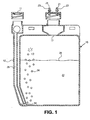
- FIG. 1 depicts a front cross-sectional view of catalyst chamber 15 for sparging a combined catalyst mixture 22.
- the catalyst chamber includes a sparging tube operatively coupled to an air inlet 14 to the catalyst chamber 15.
- the sparging tube could be a hose coupled to the air inlet 14.
- "Sparging" or "bubbling a gas through a mixture for use in an oxidation process involves passing a stream of gas through a mixture such that dispersed particles in the mixture may be non-evaporatively or mechanically/physically fluidized and carried to an oxidation flame zone by a gas stream.
- Fluidized bed is a term conventionally applied to passing a gas through a powdered solid such that the originally static powder develops fluid properties such as becoming flowable.
- sparging a gas through the liquid combined catalyst mixture 22 non-evaporatively or mechanically removes otherwise non-volatile solid catalyst particles from the liquid combined catalyst mixture 22, such that the particles become flowable or fluidized when placed into the gas stream above the liquid combined catalyst mixture 22, through the popping of the bubbles 24 at the surface of the liquid combined catalyst mixture 22.
- the catalyst particles may be carried to the flame zone by the gas stream.
- air passes through the sparging tube 12 into the catalyst chamber 15 in the direction of arrow 26 resulting in bubbles 24 passing through the combined catalyst mixture 22.
- An outlet 17 to the catalyst chamber 15 operatively couples to transfer lines 23.
- transfer lines 23 Although two transfer lines 23 are shown in the embodiment of FIG. 1 , only one or more than two may be used.
- the sparging gas may be moved in the direction of the arrow 26 by applying a vacuum to an opening 21 of a transfer line 23.
- the sparging gas may be moved in the direction of the arrow 26 by supplying a sparging gas under a positive pressure to the inlet 11 of the sparging tube 12.
- a bubble rate based on counting the number of bubbles per second released from the sparging tube 12 may be controlled by adjusting either the vacuum applied to the opening 21 of the transfer lines 23, by adjusting the pressure supplied at the sparging tube 12, or by incorporating an appropriate restriction or restrictor in the transfer line 23.
- the bubble rate may be from about 2 to about 15 bubbles per second.
- the sparging gas may be air, nitrogen, argon, helium and combinations thereof, although other gases may be used.
- the sparging gas may be a positively or negatively ionized gas, for example, selected from air, nitrogen, argon, helium and combinations thereof.
- the ionized sparging gas may be formed by exposing the sparging gas to ions from an ionizer, such as that available from All Electronics Corp., Van Nuys CA 91408 .
- the ionized sparging gas may be passed through the sparging tube 12 and the combined catalyst mixture 22 to the transfer lines 23 as described above. Though not intending to be bound by this theory, it is believed that the charged ions in the sparging gas may attract charged ions in the combined catalyst mixture 22 based on the natural attraction of positively and negatively charged ions.
- the natural attraction of the charged sparging gas and the charged catalyst ions may increase the efficiency of removal of the catalyst ions from the combined catalyst mixture 22 by the ionized sparging gas, compared to the removal of the catalyst ions by the electrically neutral sparging gas.
- the efficiency of removal of the catalyst ions from the combined catalyst mixture 22 may be increased.
- Use of ionized sparging gas may also result in a reduction in the amount of the catalyst used by the process and required for the advantages of the invention.
- Use of ionized sparging gas may result in an increase in the amount of catalyst ions conveyed to a flame zone of an oxidation process compared to the amount of catalyst ions removed from the combined catalyst mixture 22 with an electrically neutral sparging gas.
- the catalyst mixture used in the sparging process includes at least one catalyst compound which contains at least one group III element, namely Al in a matrix such as water.
- the water is preferably pure with as few contaminants as possible. Distilled water may be used.
- An Aluminum catalyst compound which is used is AlCl 3 .
- the concentration of Platinum, as H 2 PtCl 6 .6H 2 O in the catalyst mixture may be at least about 0.6 mg/ml, a concentration of Rhodium, as RhCl 3 in the catalyst mixture, is at least 0.07 mg/ml, a concentration of Rhenium, as HReO 4 (perrhenic acid) in the catalyst mixture, is at least 0.1 mg/ml, a concentration of Aluminum, as AlCl 3 in the catalyst mixture, is at least 0.07 mg/ml.
- the lron compound may be ferrocene.
- the ratio of Platinum to Rhodium is about 8.6 to 1
- the ratio of Platinum to Rhenium is about 6 to 1
- the ratio of Platinum to Aluminum is about 8.6 to 1.
- the ratios of each of the other catalyst components to Platinum may be much higher and lower than is used in this specific embodiment.
- the ratios of Platinum to Rhenium and Platinum to Aluminum may each individually range from between 30 to 1 and 1 to 1, and more specifically from between 15 to I and 2 to 1, and that ratios of Platinum to Rhodium may range from between 30 to 1 and 4 to 1, and more specifically between 15 to 1 and 4 to 1.
- the actual maximum and minimum workable ranges have not been researched fully.
- aluminium described as part of a compound within the catalyst mixture above may be acting as a sorbent for the catalyst mixture.
- An appropriate sorbent in the catalyst mixture may cause a catalyst component to be adsorbed or absorbed to the sorbent. This may assist in transferring the catalyst to the sparging gas stream through preventing the catalyst from bonding with other elements. This may also assist in reducing agglomeration of catalyst components. Both reduction of agglomeration and prevention of catalyst components bonding with each other is desirable because more catalyst particles would reach the flame zone and thereby increase the catalyst effectiveness.
- the group III element namely Aluminum acts as an accelerant within the flame zone to enable the fuel to oxidize at a lower temperature and for a longer time.
- the group III element namely Aluminum acts as an accelerant within the flame zone to enable the fuel to oxidize at a lower temperature and for a longer time.
- placing a group III element into the flame zone, particularly Aluminum creates a more electrically conductive environment within the flame zone, enabling oxidation to occur more quickly. With faster oxidation of the fuel, more of the fuel bums resulting in fewer emissions, more power output and lower burn temperature. If serving this function, the group III element would be acting as an accelerant for the oxidation process.
- the group III element, and particularly Aluminum added to the catalyst mixture functions as a sorbent, an accelerant, or serves some other function, it is clear from test results that inclusion of the group III element in the catalyst mixture provides a significant advantage to the oxidation process.
- embodiments of the catalyst mixture may include other components such as one or more sorbents, one or more antifreeze agents, one or more pH adjusters/buffers and one or more surfactants as described more fully below.
- the Lanthanide sorbent may be added to the catalyst mixture as a precursor material such as, without limitation, CeCl 3 or Ce(NO 3 ) 3 which forms sorbent particles when the sorbent precursor material reacts with water in the catalyst mixture.
- the sorbent precursor materials such as CeCl 3 or Ce(NO 3 ) 3 are particularly useful because they tend to form finely divided and easily dispersed sorbent materials in the catalyst mixture.
- Sorbent materials for example, may include alumina (Al 2 O 3 ), which is formed when AlCl 3 or Al(NO 3 ) 3 reacts with water.
- Sorbent materials may also include ceria (CeO 2 or Ce 2 O 3 ) which is formed when CeCl 3 or Ce(NO 3 ) 3 reacts with water.
- ceria CeO 2 or Ce 2 O 3
- the catalyst compound may be adsorbed or absorbed on the sorbent material as described above.
- the sorbent may comprise both alumina and ceria.
- antifreeze agents which may be added to the combined catalyst mixture in embodiments of the invention may include antifreeze agents containing an alcohol such as ethylene glycol, propylene glycol, methanol, ethanol, propanol, butanol, pentanol, hexanol, isopropy alcohol, isobutyl alcohol and combinations thereof.
- an alcohol such as ethylene glycol, propylene glycol, methanol, ethanol, propanol, butanol, pentanol, hexanol, isopropy alcohol, isobutyl alcohol and combinations thereof.
- surfactants which may be added to the combined catalyst mixture in embodiments of the invention may include ethylene glycol, other glycols, silicone oil, detergents and combinations thereof. Surfactants reduce foaming of the combined catalyst mixture in the catalyst chamber, caused when the bubbles break the surface of the combined catalyst mixture. This allows the catalyst particles to more easily be transferred to the atmosphere above the surface of the combined catalyst mixture and be carried away by the gas stream.
- the pH of the combined catalyst mixture composition of embodiments of the invention should be such that agglomeration of particles is substantially avoided.
- Agglomerated particles are undesirable because agglomerated particles are more difficult to convey out of the combined catalytic mixture by the stream of air, at least in part because they are heavier than non-agglomerated particles. It has been found that for the compositions of the combined catalyst mixtures of embodiments of the invention, a pH of less than about 4.0 is desirable for its efficacy in preventing formation of agglomerated particles. Above a pH of about 4.0, the catalyst components were shown to agglomerate within the catalyst chamber.
- a pH in a range of about 1.4 to about 3.0 is used. In a more specific embodiment of the invention, a pH of between about 1.6 to about 2.2 is used.
- the pH of the combined catalyst mixture may be adjusted by adding appropriate amounts of an acid and/or a base.
- the pH of the combined catalyst mixture may also be adjusted by using an appropriate buffer such as tris (hydroxymethyl) aminomethane and citric acid monohydrate buffers. Examples of other compounds known to be useful in discouraging agglomeration are lithium chloride (LiCl), sodium chloride (NaCl), and HCl.
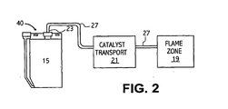
- FIG. 2 depicts a catalyst delivery system 40 for transporting catalyst particles to a flame zone 19 of an oxidation process.
- the flame zone 19 may be an enclosed flame zone or an open flame zone.
- the catalyst particles sparged from the combined catalyst mixture within the catalyst chamber 15 are transported to the flame zone 19 by a catalyst transport 21.
- the catalyst transport 21 may be as simple as a tube coupled to an air intake to the flame zone 19, or may include one or more of the following to direct, regulate, monitor and control flow of the catalyst particles to the flame zone 19: pumps, injectors, restrictors, orifices controllers, regulators and other components.
- the catalyst particles are transported from the catalyst chamber 15 to the flame zone 19 by the sparging gas stream through transport line 27.
- the combined catalyst mixture or catalyst particles may be directly injected into line 27 and swept by the sparging gas to the flame zone 19.
- a combustion air and/or inert gas feed line(s) 27 may be operatively attached to the transfer line 23 to sweep the sparging gas or a directly injected combined catalyst mixture into the flame zone 19.
- the combustion air may be provided, for example, by forced air induction.
- the catalyst particles are delivered to the flame zone 19 and are mixed with the combustion air to affect the chemical environment of the flame zone for oxidizing fuel.
- the catalyst particles are delivered to the flame zone 19 of the incinerator to affect the chemical environment within the flame zone.
- the invention is also believed to reduce Sulfur Oxide emissions, such as SO x where x equals 2 or 3. Additional catalysts, such as ferrocene, may be added and are known to specifically reduce SOx emissions.
- Nonlimiting examples of the fuel with which the combined catalyst mixtures of embodiments of the invention may be used are number 2 fuel oil, fuel oils refined from crude oil, diesel fuel, gasoline, compressed or liquified natural gas, gasohol, any hydrocarbon having one or more carbon atoms such as methane, ethane, propane, butane, isobutane, toluene, xylene, octane, benzene, mixtures of alcohols having methanol, ethanol, propanol, butanol, isopropanol, isobutanol, pentanol, hexanol, heptanol, octanol, vegetable oil such as corn oil, mineral oil, coal, coal gas, asphalt vapor, oxidizable
- FIG. 3 depicts a method 30 for oxidizing a fuel.
- the fuel is oxidized by providing a fuel to be oxidized, and a combined catalyst mixture of the invention (step 32), mixing catalyst particles with combustion air (step 34), mixing the catalyst-containing air with the fuel (step 36) and oxidizing the fuel (step 38).
- the catalyst may be transported from the combined catalyst mixture to the flame zone (step 34) by a sparging gas stream to a combustion air intake to the flame zone, may be directly injected into the combustion air intake to the flame zone, or may be directly injected into the flame zone.
- the fuel may be transported to the flame zone by any method known and used in the art including, without limitation, direct injection.
- the various catalyst particles may alternatively be placed into the combustion air separately by separate sparging processes or injection.
- Catalysts for mixing with fuel in a fuel tank also called fuel additives
- the catalyst particles attach to the fuel.
- the fuel shields most if not all of the catalyst particles from catalyzing the combustion air if the liquid fuel and catalyst are pre-mixed.
- the combined catalyst mixtures of the present invention are not to be confused with fuel additives.
- the catalysts By catalyzing the combustion air prior to mixing it with fuel, the catalysts are excited and thus more active than when pre-mixed with liquid fuel. Accordingly, the catalysts further accelerate the separation of oxygen in the combustion air.
- the catalyst-containing combustion air within the environment of the flame zone is, therefore, catalyzed before combustion which enhances the oxidation of the fuel more fully than when the catalyst is merely mixed with the fuel in liquid form.
- the catalyst particles subsequently mix with the fuel for oxidation, they also catalyze the fuel. Catalyst mixed directly into liquid fuel has very little, if any, opportunity to catalyze the flame zone environment prior to oxidation of the fuel.
- a gasoline fuel may be oxidized in accordance with the method and composition disclosed herein.
- the current Example relates to a gasoline fuel engine having a fuel consumption rate of 5 gallons per hour operating for at least 400 hours, thereby consuming approximately two thousand (2,000) gallons (6056 kilograms) of fuel.
- a typical car consumes approximately 5 gallons/hour.
- the engine is provided with a catalyst delivery system as shown in FIG. 1 .
- the specific catalyst mixture for a fuel rate of 5 gal/hour for this Example is as follows:
- 36ml of catalyst mixture in 650 ml of combined catalyst mixture may be sparged for a period of at least 400 hrs. at a bubble rate of between about 4-6 bubbles per second and still be effective.
- the sparged air of the present Example which contains catalyst particles is placed into the air intake of the combustion chamber of the gasoline engine.
- the concentration of catalyst mixture in the combined catalyst mixture may be adjusted for engines having higher fuel consumption rates so that the combined catalyst mixture of 650 ml includes approximately 36 ml of catalyst mixture for each 5 gal/hour of fuel consumption. Accordingly, the catalyst mixture may be produced, sold and distributed separately from the base liquid, and added to the base liquid in the catalyst chamber as needed by an end user such as a car owner. Test results indicate that when there is more than approximately 160 ml of catalyst mixture in the combined catalyst mixture of 650 ml, the benefits of adding more catalyst mixture are reduced. In cases with engines consuming more than approximately 22.5 gal/hour of fuel, more than one liquid catalyst dispenser may be needed for full effectiveness. Test results also indicate that adding more Aluminum to the catalyst mixture, even doubling it to .56 mg/ml, provides better performance results than with less Aluminum. Nevertheless, even in engines using a catalyst mixture with relatively small amounts of Aluminum performed better than without any Aluminum.
- Changing the chemistry of the flame zone environment through the use of combined catalyst mixtures of the invention may affect the chemistry of the interactions and oxidations of the various fuel and catalyst elements, and may even alter the oxidizing temperature of the fuel.
- Studies by other researchers have indicated that plating a combustion chamber with Platinum reduced harmful emissions and reduced cyclonic temperatures of the combustion gases from approximately 330 °C to approximately 220 °C. Reduced cyclonic temperatures of the combustion gases is believed to further extend the burn time of the combustion process.
- Example 1 Under the description provided in Example 1, 144 ml of catalyst mixture is sufficient for about 20 gal/hour of fuel consumption. Under 85% load, the Catepillar engine ordinarily consumes approximately 23 gal/hour. Thus, the catalyst mixture was run lean for these tests. The tests discussed are standardized industry tests performed on appropriate calibrated equipment and will be clear to those of ordinary skill in the art.
- the horsepower (Hp) of the engine was measured without the addition of catalyst to the combustion chamber and found to be about 447 Hp.
- the horsepower of the engine was found to be 520 Hp. This reflects a 16.3 % increase in horsepower (Hp) through the use of a combined catalyst mixture of the invention as compared to operating the same engine under the same conditions without the addition of catalyst into the engine combustion chamber.
- An electronic inductive pickup (tachometer sensor) of a CSI 2120A Machine Analyzer was used to measure torsional vibration.
- Table 1 reflects the engine's torsional vibration without catalyst being sparged from the combined catalyst mixture into the engine, and the torsional vibration of the engine with catalyst being sparged into the engine.
- “Overall (G-DG)” is the difference in degrees between measurements
- “RMS” is the root mean square of the relative average degree of change of all measurements
- “Load” indicates that the engines were operating at 100% load
- “RPM” is revolutions per minute
- RPS revolutions per second.
- Table 2 reflects the change in the engine's torsional vibration for the harmonics of the engine's vibration with the addition of catalyst particles to the combustion air intake stream.
- the ultra-sonic energy of the engine was measured using an specific accelerometer of a CSI 2120A Machine Analyzer.
- Table 3 reflects the ultra-sonic energy of the engine without catalyst being sparged from the combined catalyst mixture into the engine, and the ultra-sonic energy of the engine with catalyst being sparged into the engine.
- RMS is the root mean square of the ultra-sonic wave form
- Load indicates that the engines were operating at 100% load
- RPM revolutions per minute
- RPS revolutions per second
- PK(+) and PK(-) represent, respectively, the positive and negative peaks of the vibrations in standard units
- “CrestF” is the ratio between the average and the peak value.
- the ultra-sonic energy of a reciprocating engine is an indicator of the power and smoothness of the engine.
- the ultra-sonic energy increases, this is an indication that the fuel combustion is more powerful and more even. More powerful may mean the power impulse is either stronger or longer. Accordingly, the tests indicate approximately a 3.3 dB or 8.13 % increase in the ultra-sonic energy (when averaged over cylinders 1,3,5,and 7) of the engine through the use of catalyst within the combustion air as compared to no catalyst in the combustion air.
Applications Claiming Priority (5)
| Application Number | Priority Date | Filing Date | Title |
|---|---|---|---|
| US27328301P | 2001-03-02 | 2001-03-02 | |
| US273283P | 2001-03-02 | ||
| US35577302P | 2002-02-09 | 2002-02-09 | |
| US355773P | 2002-02-09 | ||
| PCT/US2002/006578 WO2002070632A2 (en) | 2001-03-02 | 2002-03-02 | Catalyst composition and method for oxidizing mixtures |
Publications (3)
| Publication Number | Publication Date |
|---|---|
| EP1390450A2 EP1390450A2 (en) | 2004-02-25 |
| EP1390450A4 EP1390450A4 (en) | 2004-10-20 |
| EP1390450B1 true EP1390450B1 (en) | 2008-05-14 |
Family
ID=26956067
Family Applications (1)
| Application Number | Title | Priority Date | Filing Date |
|---|---|---|---|
| EP02723320A Expired - Lifetime EP1390450B1 (en) | 2001-03-02 | 2002-03-02 | Catalyst composition and method for oxidizing mixtures |
Country Status (15)
| Country | Link |
|---|---|
| US (3) | US6776606B2 (zh) |
| EP (1) | EP1390450B1 (zh) |
| JP (1) | JP4131669B2 (zh) |
| CN (1) | CN100584450C (zh) |
| AT (1) | ATE395398T1 (zh) |
| AU (1) | AU2002254105A1 (zh) |
| BR (1) | BR0207660A (zh) |
| CA (1) | CA2439995A1 (zh) |
| DE (1) | DE60226598D1 (zh) |
| DK (1) | DK200301438A (zh) |
| ES (1) | ES2310203T3 (zh) |
| GB (1) | GB2398521B (zh) |
| HK (1) | HK1076767A1 (zh) |
| MX (1) | MXPA03007875A (zh) |
| WO (1) | WO2002070632A2 (zh) |
Families Citing this family (35)
| Publication number | Priority date | Publication date | Assignee | Title |
|---|---|---|---|---|
| US6786714B2 (en) * | 2001-04-12 | 2004-09-07 | James W. Haskew | Delivery system for liquid catalysts |
| US7569508B2 (en) * | 2004-11-17 | 2009-08-04 | Headwaters Technology Innovation, Llc | Reforming nanocatalysts and method of making and using such catalysts |
| US7655137B2 (en) | 2003-07-14 | 2010-02-02 | Headwaters Technology Innovation, Llc | Reforming catalysts having a controlled coordination structure and methods for preparing such compositions |
| AU2004317168B2 (en) * | 2004-03-12 | 2010-03-18 | Qitai Zhang | A light hydrocarbon fuel, the method and apparatus for its gasification |
| US7584905B2 (en) * | 2004-11-08 | 2009-09-08 | Emissions Technology, Inc. | Fuel combustion catalyst microburst aerosol delivery device and continuous and consistent aerosol delivery device |
| WO2006052909A2 (en) * | 2004-11-08 | 2006-05-18 | Emissions Technology, Inc. | Fuel combustion catalyst microburst aerosol delivery device and continuous and consistent aerosol delivery device |
| US7632775B2 (en) * | 2004-11-17 | 2009-12-15 | Headwaters Technology Innovation, Llc | Multicomponent nanoparticles formed using a dispersing agent |
| US7856992B2 (en) * | 2005-02-09 | 2010-12-28 | Headwaters Technology Innovation, Llc | Tobacco catalyst and methods for reducing the amount of undesirable small molecules in tobacco smoke |
| US7803201B2 (en) * | 2005-02-09 | 2010-09-28 | Headwaters Technology Innovation, Llc | Organically complexed nanocatalysts for improving combustion properties of fuels and fuel compositions incorporating such catalysts |
| DE102005015520A1 (de) * | 2005-04-04 | 2006-11-09 | Superfeuer Gmbh | Sprühflasche |
| US7357903B2 (en) * | 2005-04-12 | 2008-04-15 | Headwaters Heavy Oil, Llc | Method for reducing NOx during combustion of coal in a burner |
| US7093429B1 (en) * | 2005-06-01 | 2006-08-22 | Gm Global Technology Operations Inc. | Reforming diesel fuel for NOx reduction |
| US20110023927A1 (en) * | 2005-07-08 | 2011-02-03 | Irvine Sensors Corporation | Micro-combustion power system with metal foam heat exchanger |
| US7758660B2 (en) | 2006-02-09 | 2010-07-20 | Headwaters Technology Innovation, Llc | Crystalline nanocatalysts for improving combustion properties of fuels and fuel compositions incorporating such catalysts |
| US7541309B2 (en) * | 2006-05-16 | 2009-06-02 | Headwaters Technology Innovation, Llc | Reforming nanocatalysts and methods of making and using such catalysts |
| US20100120608A1 (en) * | 2006-06-02 | 2010-05-13 | Haskew James W | Reactive metal and catalyst amalgam and method for improving the combustibility of fuel oils |
| US20070281252A1 (en) * | 2006-06-02 | 2007-12-06 | Haskew James W | Reactive metal and catalyst amalgam and method for improving the combustibility of fuel oils |
| US8366312B1 (en) | 2006-08-01 | 2013-02-05 | United Services Automobile Association (Usaa) | Systems to store and agitate fuel |
| US7654231B1 (en) | 2006-08-01 | 2010-02-02 | United Services Automobile Association (Usaa) | System and method for powering a vehicle |
| US7527046B1 (en) * | 2006-08-01 | 2009-05-05 | United Services Automobile Association (Usaa) | System and method for generating power |
| US7601668B2 (en) * | 2006-09-29 | 2009-10-13 | Headwaters Technology Innovation, Llc | Methods for manufacturing bi-metallic catalysts having a controlled crystal face exposure |
| CN101932589B (zh) * | 2008-01-31 | 2016-02-10 | 亚什兰许可和知识产权有限公司 | 包含某些茂金属的组合物及其用途 |
| US9139791B2 (en) * | 2008-02-13 | 2015-09-22 | Hydrocoal Technologies, Llc | Processing device for improved utilization of fuel solids |
| US8460407B2 (en) * | 2008-02-13 | 2013-06-11 | David Walker Taylor | Form of coal particles |
| US8177864B1 (en) | 2008-05-22 | 2012-05-15 | Environmental Bio-Fuels, Inc. | Fuel and fuel additive |
| JP5616333B2 (ja) * | 2008-05-29 | 2014-10-29 | アドバンスト・マイクロ・ディバイシズ・インコーポレイテッドAdvanced Micro Devices Incorporated | ジオメトリシェーダを用いる平面充填エンジンのためのシステム、方法及びコンピュータプログラム |
| US20100064952A1 (en) * | 2008-09-03 | 2010-03-18 | Lawrence George Brown | Method and Means for Using Commom Dusts as Fuel for and Engine |
| US8033167B2 (en) * | 2009-02-24 | 2011-10-11 | Gary Miller | Systems and methods for providing a catalyst |
| WO2010098746A1 (en) * | 2009-02-24 | 2010-09-02 | Gary Miller | Systems and methods for providing a catalyst |
| US10718511B2 (en) | 2010-07-02 | 2020-07-21 | Harry R. Taplin, JR. | System for combustion of fuel to provide high efficiency, low pollution energy |
| US8852300B2 (en) * | 2010-07-02 | 2014-10-07 | Harry R. Taplin, JR. | Lithium conditioned engine with reduced carbon oxide emissions |
| WO2012051161A2 (en) * | 2010-10-12 | 2012-04-19 | Emissions Technology, Inc. | A method for reducing engine emissions using a liquid aerosol catalyst |
| WO2017031598A1 (en) * | 2015-08-27 | 2017-03-02 | Westport Power Inc. | Deposit mitigation for gaseous fuel injectors |
| FR3102514B1 (fr) * | 2019-10-28 | 2021-11-12 | Ecosoftec | Moteur à faible émission de particules |
| CN112146154A (zh) * | 2020-08-18 | 2020-12-29 | 广东醇氢新能源研究院有限公司 | 快速启动的供暖方法 |
Family Cites Families (67)
| Publication number | Priority date | Publication date | Assignee | Title |
|---|---|---|---|---|
| US145758A (en) * | 1873-12-23 | Improvement in inhaling apparatus | ||
| US780077A (en) * | 1903-09-09 | 1905-01-17 | Sophie W Gage | Medical vaporizer. |
| US1057254A (en) * | 1905-11-03 | 1913-03-25 | William H Mcandrews | Carbureter. |
| US1391311A (en) * | 1920-02-07 | 1921-09-20 | Clarence M Frost | Aerated water-supply device |
| US1664333A (en) * | 1926-10-26 | 1928-03-27 | Doc G Taylor | Air cleaner |
| US2086775A (en) | 1936-07-13 | 1937-07-13 | Leo Corp | Method of operating an internal combustion engine |
| US3189030A (en) * | 1961-07-27 | 1965-06-15 | Rupp Otto | Inhaling device |
| US3615836A (en) | 1964-09-04 | 1971-10-26 | Exxon Research Engineering Co | Fuel cell containing and a process of making an activated fuel cell catalyst |
| US3940923A (en) | 1971-05-13 | 1976-03-02 | Engelhard Minerals & Chemicals Corporation | Method of operating catalytically supported thermal combustion system |
| US3800768A (en) | 1972-02-28 | 1974-04-02 | Standard Oil Co | Apparatus and method for fueling an internal combustion engine |
| GB1431893A (en) | 1972-06-13 | 1976-04-14 | Chai Mun Leon I C | Engine |
| DE2304831C3 (de) * | 1973-02-01 | 1978-06-22 | Kali-Chemie Ag, 3000 Hannover | Verfahren zur katalytischen Entfernung von Kohlenmonoxid, unverbrannten Kohlenwasserstoffen und Stickoxiden aus Autoabgasen |
| AR208304A1 (es) | 1974-01-02 | 1976-12-20 | Wentworth F | Un metodo para agregar vapor de agua a la mezcla combustible en un aparato de combustion que tiene una admision forzada de aire y un aparato para ilevar a cabo el metodo |
| US5558513A (en) * | 1974-01-02 | 1996-09-24 | Ionic Fuel Technology, Inc. | Vapor catalyst system for combustion |
| US4170200A (en) | 1974-06-14 | 1979-10-09 | Nippondenso Co., Ltd. | Internal combustion engine with reformed gas generator |
| US4036919A (en) * | 1974-06-26 | 1977-07-19 | Inhalation Therapy Equipment, Inc. | Nebulizer-humidifier system |
| US4061698A (en) * | 1975-04-18 | 1977-12-06 | Aerwey Laboratories, Inc. | Humidifier-nebulizer apparatus |
| US4013076A (en) * | 1975-06-17 | 1977-03-22 | Diemolding Corporation | Aspirator jar |
| US4090838A (en) | 1976-03-17 | 1978-05-23 | Kenneth R. Schena | Catalyst generator |
| US4014637A (en) * | 1976-03-01 | 1977-03-29 | Schena Kenneth R | Catalyst generator |
| US4009984A (en) * | 1976-03-08 | 1977-03-01 | Morrison Charles F | Vapor injection system for fuel combustion |
| US4152378A (en) * | 1977-03-14 | 1979-05-01 | Baxter Travenol Laboratories, Inc. | Container closure having automatic opening means |
| US4295816A (en) | 1977-12-20 | 1981-10-20 | Robinson B Joel | Catalyst delivery system |
| US4493637A (en) | 1978-02-15 | 1985-01-15 | Thermics Corporation Liquidating Trust | Fossil fuel catalyst generator |
| FR2460156A1 (fr) * | 1979-06-29 | 1981-01-23 | Anvar | Procede de mise en contact d'une phase gazeuse, d'au moins une phase liquide et d'au moins une phase solide a l'etat divise |
| US4235754A (en) | 1979-08-10 | 1980-11-25 | Mobil Oil Corporation | Cracking catalyst |
| US4382017A (en) * | 1980-09-02 | 1983-05-03 | Robinson Charles A | Means and method for providing a non-freezing catalyst solution |
| IT1205425B (it) | 1980-10-14 | 1989-03-23 | Andrea Venturini | Impianto di catalizzazione della combustione di combustibili commerciali |
| JPS5776005A (en) * | 1980-10-31 | 1982-05-12 | Nippon Oil Co Ltd | Vapor-phase polymerizing apparatus of olefin |
| US4388877A (en) * | 1981-07-07 | 1983-06-21 | Benmol Corporation | Method and composition for combustion of fossil fuels in fluidized bed |
| US4367182A (en) * | 1981-07-14 | 1983-01-04 | American Hospital Supply Corporation | Container with incorporated aerator |
| US4410467A (en) | 1981-11-09 | 1983-10-18 | Wentworth Fred Albert Jr | Ion-vapor generator and method |
| US4432721A (en) * | 1981-12-29 | 1984-02-21 | Testco, Inc. | Combustion air bubble chamber method |
| US4440874A (en) | 1982-04-14 | 1984-04-03 | Engelhard Corporation | Catalyst composition and method for its manufacture |
| US4802335A (en) | 1982-07-29 | 1989-02-07 | Stephen Masiuk | Method of and apparatus for improving the efficiency of internal combustion engines |
| US4475483A (en) | 1983-04-15 | 1984-10-09 | Robinson Barnett J | Catalyst delivery system |
| WO1985002346A1 (en) * | 1983-11-28 | 1985-06-06 | Vortran Corporation | Gas-powered nebulizer |
| US4548232A (en) * | 1984-04-12 | 1985-10-22 | Panlmatic Company | Valve assembly |
| HU205446B (en) | 1984-11-16 | 1992-04-28 | Benno Balsiger | Device for activating the combustion process |
| DE3503413A1 (de) | 1985-02-01 | 1986-08-07 | Christian Dr.-Ing. 8570 Pegnitz Koch | Verfahren und vorrichtung zur vierstufigen verbrennung von gasfoermigen und fluessigen brennstoffen mit stickoxidfreien abgasen |
| US4629472A (en) | 1985-06-19 | 1986-12-16 | Fuel Tech, Inc. | Method and apparatus for improving combustion, thermal efficiency and reducing emissions by treating fuel |
| GB8518576D0 (en) | 1985-07-23 | 1985-08-29 | Bp Chem Int Ltd | Hydrogenation of carboxylic acid esters to alcohols |
| US5501714A (en) | 1988-12-28 | 1996-03-26 | Platinum Plus, Inc. | Operation of diesel engines with reduced particulate emission by utilization of platinum group metal fuel additive and pass-through catalytic oxidizer |
| US5085841A (en) | 1990-07-13 | 1992-02-04 | Robinson Barnett J | Method for reduction of pollution from combustion chambers |
| DE4110337A1 (de) | 1991-03-28 | 1992-10-01 | Siemens Ag | Verfahren und einrichtung zur regeneration verbrauchter deno(pfeil abwaerts)x(pfeil abwaerts)-katalysatoren |
| US5129926A (en) * | 1991-07-22 | 1992-07-14 | Harwell James E | Engine exhaust system |
| DE9113446U1 (zh) * | 1991-10-29 | 1992-01-16 | Kendall Medizinische Erzeugnisse Gmbh, 8425 Neustadt, De | |
| US5460790A (en) | 1992-02-25 | 1995-10-24 | Blue Planet Technologies Co., L.P. | Catalytic vessel for receiving metal catalysts by deposition from the gas phase |
| US5387569A (en) * | 1992-02-25 | 1995-02-07 | Blue Planet Technologies Co., L.P. | Catalytic solution suitable for converting combustion emissions |
| AU671624B2 (en) | 1992-02-25 | 1996-09-05 | Blue Planet Technologies Co. L.P. | Catalytic system |
| US5331924A (en) | 1992-03-12 | 1994-07-26 | Kraus Gregory A | Catalytic liquid injection system for emission control |
| US5340383A (en) * | 1993-11-12 | 1994-08-23 | Freeport-Mcmoran Inc. | Reduction of particulate sulfur emissions from liquid sulfur storage tanks |
| SE502452C2 (sv) * | 1994-02-25 | 1995-10-23 | Rosen | Sätt att tillföra ånga till insugsluften till en förbränningsmotor och en anordning därtill |
| DE4446893A1 (de) | 1994-12-27 | 1996-07-04 | Basf Ag | Verfahren zur Herstellung von aliphatischen alpha,omega-Aminonitrilen |
| US5785930A (en) | 1996-09-17 | 1998-07-28 | Sinclair; Douglas Stewart | Apparatus for burning a wide variety of fuels in air which produces low levels of nitric oxide and carbon monoxide emissions |
| US5851498A (en) | 1996-12-02 | 1998-12-22 | Catalytic Systems Technologies, Ltd. | Boiler heated by catalytic combustion |
| DE19653200A1 (de) | 1996-12-19 | 1998-06-25 | Basf Ag | Verfahren zur Reduktion von Stickoxiden |
| US5976475A (en) | 1997-04-02 | 1999-11-02 | Clean Diesel Technologies, Inc. | Reducing NOx emissions from an engine by temperature-controlled urea injection for selective catalytic reduction |
| US5924280A (en) | 1997-04-04 | 1999-07-20 | Clean Diesel Technologies, Inc. | Reducing NOx emissions from an engine while maximizing fuel economy |
| US5968464A (en) | 1997-05-12 | 1999-10-19 | Clean Diesel Technologies, Inc. | Urea pyrolysis chamber and process for reducing lean-burn engine NOx emissions by selective catalytic reduction |
| KR19990006241A (ko) | 1997-06-20 | 1999-01-25 | 비라마니 알 | 식물성 촉매 조성물 및 장치 |
| US6176701B1 (en) | 1997-10-01 | 2001-01-23 | Barnett Joel Robinson | Method for improving fuel efficiency in combustion chambers |
| US5908491A (en) * | 1997-12-08 | 1999-06-01 | Hobbs; Roy | Air cleaner |
| DE19813053C2 (de) | 1998-03-25 | 2001-10-18 | Xcellsis Gmbh | Reaktoreinheit für eine katalytische chemische Reaktion, insbesondere zur katalytischen Methanolreformierung |
| US6013599A (en) | 1998-07-15 | 2000-01-11 | Redem Corporation | Self-regenerating diesel exhaust particulate filter and material |
| US6230698B1 (en) * | 2000-02-01 | 2001-05-15 | D. Robert Shaw | Engine pollutant filter system |
| US6419477B1 (en) | 2000-09-28 | 2002-07-16 | Barnett Joel Robinson | Method for improving fuel efficiency in combustion chambers |
-
2002
- 2002-03-01 US US10/087,139 patent/US6776606B2/en not_active Expired - Lifetime
- 2002-03-02 CN CN02809316A patent/CN100584450C/zh not_active Expired - Fee Related
- 2002-03-02 GB GB0320507A patent/GB2398521B/en not_active Expired - Fee Related
- 2002-03-02 WO PCT/US2002/006578 patent/WO2002070632A2/en active Application Filing
- 2002-03-02 DE DE60226598T patent/DE60226598D1/de not_active Expired - Lifetime
- 2002-03-02 BR BR0207660-8A patent/BR0207660A/pt not_active IP Right Cessation
- 2002-03-02 ES ES02723320T patent/ES2310203T3/es not_active Expired - Lifetime
- 2002-03-02 AU AU2002254105A patent/AU2002254105A1/en not_active Abandoned
- 2002-03-02 AT AT02723320T patent/ATE395398T1/de not_active IP Right Cessation
- 2002-03-02 JP JP2002570660A patent/JP4131669B2/ja not_active Expired - Fee Related
- 2002-03-02 CA CA002439995A patent/CA2439995A1/en not_active Abandoned
- 2002-03-02 MX MXPA03007875A patent/MXPA03007875A/es active IP Right Grant
- 2002-03-02 EP EP02723320A patent/EP1390450B1/en not_active Expired - Lifetime
-
2003
- 2003-10-02 DK DK200301438A patent/DK200301438A/da not_active Application Discontinuation
-
2004
- 2004-08-03 US US10/910,973 patent/US20050054522A1/en not_active Abandoned
- 2004-09-30 US US10/956,776 patent/US20050053875A1/en not_active Abandoned
-
2005
- 2005-09-29 HK HK05108661.6A patent/HK1076767A1/xx not_active IP Right Cessation
Also Published As
| Publication number | Publication date |
|---|---|
| CN100584450C (zh) | 2010-01-27 |
| EP1390450A2 (en) | 2004-02-25 |
| HK1076767A1 (en) | 2006-01-27 |
| MXPA03007875A (es) | 2004-12-06 |
| US20050053875A1 (en) | 2005-03-10 |
| EP1390450A4 (en) | 2004-10-20 |
| WO2002070632A9 (en) | 2002-11-14 |
| ATE395398T1 (de) | 2008-05-15 |
| GB2398521B (en) | 2005-12-21 |
| AU2002254105A1 (en) | 2002-09-19 |
| US6776606B2 (en) | 2004-08-17 |
| BR0207660A (pt) | 2004-09-21 |
| GB2398521A (en) | 2004-08-25 |
| WO2002070632A3 (en) | 2003-12-18 |
| DE60226598D1 (de) | 2008-06-26 |
| US20050054522A1 (en) | 2005-03-10 |
| CA2439995A1 (en) | 2002-09-12 |
| US20020165088A1 (en) | 2002-11-07 |
| CN1602227A (zh) | 2005-03-30 |
| GB0320507D0 (en) | 2003-10-01 |
| ES2310203T3 (es) | 2009-01-01 |
| JP4131669B2 (ja) | 2008-08-13 |
| DK200301438A (da) | 2003-10-02 |
| JP2005502802A (ja) | 2005-01-27 |
| WO2002070632A2 (en) | 2002-09-12 |
Similar Documents
| Publication | Publication Date | Title |
|---|---|---|
| EP1390450B1 (en) | Catalyst composition and method for oxidizing mixtures | |
| EP1299508B1 (en) | A fuel additive | |
| RU2386078C2 (ru) | Система доставки каталитического аэрозоля и способ катализирования горения топлива | |
| JPH11502242A (ja) | ディーゼルエンジンにおける白金族の利用 | |
| US6152972A (en) | Gasoline additives for catalytic control of emissions from combustion engines | |
| WO2009090760A1 (ja) | 燃料添加剤 | |
| JPWO2009075317A1 (ja) | 含油水を用いて乳化燃料を製造する方法 | |
| KR100947332B1 (ko) | 압축-점화식 왕복기관을 위한 연기 및 입자 방출 감소방법 | |
| MXPA03000683A (es) | Aditivo para reducir material particulado en emisiones que provienen de la combustion de diesel. | |
| TWI398512B (zh) | 複合燃料乳劑,及該乳劑與水乳化所製備之複合燃料乳液,以及該乳劑及該乳液之製備方法及其應用 | |
| KR19990085956A (ko) | 벙커-씨유를 원료로 하는 정제연료유의 제조방법과 그 장치 | |
| JPH11514044A (ja) | エマルジョン燃料 | |
| AU2005203020B2 (en) | A fuel additive | |
| WO2020159392A1 (en) | Process for the additivation of the combustion process in spark ignition engines, composition, device and method for the application of the process | |
| JPH07208148A (ja) | ターボチャージャーを具備した機関の管路を清浄に保つ方法及び清浄化剤 | |
| JP2001342469A (ja) | 重質油組成物 | |
| CA2751601A1 (en) | Lanthanide oxide particles |
Legal Events
| Date | Code | Title | Description |
|---|---|---|---|
| PUAI | Public reference made under article 153(3) epc to a published international application that has entered the european phase |
Free format text: ORIGINAL CODE: 0009012 |
|
| 17P | Request for examination filed |
Effective date: 20031028 |
|
| AK | Designated contracting states |
Kind code of ref document: A2 Designated state(s): AT BE CH CY DE DK ES FI FR GB GR IE IT LI LU MC NL PT SE TR |
|
| AX | Request for extension of the european patent |
Extension state: AL LT LV MK RO SI |
|
| A4 | Supplementary search report drawn up and despatched |
Effective date: 20040903 |
|
| RIC1 | Information provided on ipc code assigned before grant |
Ipc: 7B 01J 23/656 B Ipc: 7C 10L 1/00 A |
|
| GRAP | Despatch of communication of intention to grant a patent |
Free format text: ORIGINAL CODE: EPIDOSNIGR1 |
|
| GRAS | Grant fee paid |
Free format text: ORIGINAL CODE: EPIDOSNIGR3 |
|
| GRAA | (expected) grant |
Free format text: ORIGINAL CODE: 0009210 |
|
| AK | Designated contracting states |
Kind code of ref document: B1 Designated state(s): AT BE CH CY DE DK ES FI FR GB GR IE IT LI LU MC NL PT SE TR |
|
| REG | Reference to a national code |
Ref country code: GB Ref legal event code: FG4D |
|
| REG | Reference to a national code |
Ref country code: CH Ref legal event code: EP |
|
| REG | Reference to a national code |
Ref country code: IE Ref legal event code: FG4D Free format text: LANGUAGE OF EP DOCUMENT: FRENCH |
|
| REF | Corresponds to: |
Ref document number: 60226598 Country of ref document: DE Date of ref document: 20080626 Kind code of ref document: P |
|
| REG | Reference to a national code |
Ref country code: SE Ref legal event code: TRGR |
|
| PG25 | Lapsed in a contracting state [announced via postgrant information from national office to epo] |
Ref country code: FI Free format text: LAPSE BECAUSE OF FAILURE TO SUBMIT A TRANSLATION OF THE DESCRIPTION OR TO PAY THE FEE WITHIN THE PRESCRIBED TIME-LIMIT Effective date: 20080514 |
|
| NLV1 | Nl: lapsed or annulled due to failure to fulfill the requirements of art. 29p and 29m of the patents act | ||
| PG25 | Lapsed in a contracting state [announced via postgrant information from national office to epo] |
Ref country code: NL Free format text: LAPSE BECAUSE OF FAILURE TO SUBMIT A TRANSLATION OF THE DESCRIPTION OR TO PAY THE FEE WITHIN THE PRESCRIBED TIME-LIMIT Effective date: 20080514 Ref country code: AT Free format text: LAPSE BECAUSE OF FAILURE TO SUBMIT A TRANSLATION OF THE DESCRIPTION OR TO PAY THE FEE WITHIN THE PRESCRIBED TIME-LIMIT Effective date: 20080514 |
|
| REG | Reference to a national code |
Ref country code: ES Ref legal event code: FG2A Ref document number: 2310203 Country of ref document: ES Kind code of ref document: T3 |
|
| PG25 | Lapsed in a contracting state [announced via postgrant information from national office to epo] |
Ref country code: DK Free format text: LAPSE BECAUSE OF FAILURE TO SUBMIT A TRANSLATION OF THE DESCRIPTION OR TO PAY THE FEE WITHIN THE PRESCRIBED TIME-LIMIT Effective date: 20080514 Ref country code: PT Free format text: LAPSE BECAUSE OF FAILURE TO SUBMIT A TRANSLATION OF THE DESCRIPTION OR TO PAY THE FEE WITHIN THE PRESCRIBED TIME-LIMIT Effective date: 20081014 |
|
| PG25 | Lapsed in a contracting state [announced via postgrant information from national office to epo] |
Ref country code: BE Free format text: LAPSE BECAUSE OF FAILURE TO SUBMIT A TRANSLATION OF THE DESCRIPTION OR TO PAY THE FEE WITHIN THE PRESCRIBED TIME-LIMIT Effective date: 20080514 |
|
| PLBE | No opposition filed within time limit |
Free format text: ORIGINAL CODE: 0009261 |
|
| STAA | Information on the status of an ep patent application or granted ep patent |
Free format text: STATUS: NO OPPOSITION FILED WITHIN TIME LIMIT |
|
| 26N | No opposition filed |
Effective date: 20090217 |
|
| PG25 | Lapsed in a contracting state [announced via postgrant information from national office to epo] |
Ref country code: MC Free format text: LAPSE BECAUSE OF NON-PAYMENT OF DUE FEES Effective date: 20090331 |
|
| REG | Reference to a national code |
Ref country code: CH Ref legal event code: PL |
|
| PG25 | Lapsed in a contracting state [announced via postgrant information from national office to epo] |
Ref country code: CH Free format text: LAPSE BECAUSE OF NON-PAYMENT OF DUE FEES Effective date: 20090331 Ref country code: LI Free format text: LAPSE BECAUSE OF NON-PAYMENT OF DUE FEES Effective date: 20090331 |
|
| PG25 | Lapsed in a contracting state [announced via postgrant information from national office to epo] |
Ref country code: GR Free format text: LAPSE BECAUSE OF FAILURE TO SUBMIT A TRANSLATION OF THE DESCRIPTION OR TO PAY THE FEE WITHIN THE PRESCRIBED TIME-LIMIT Effective date: 20080815 |
|
| PG25 | Lapsed in a contracting state [announced via postgrant information from national office to epo] |
Ref country code: IT Free format text: LAPSE BECAUSE OF NON-PAYMENT OF DUE FEES Effective date: 20090302 |
|
| PG25 | Lapsed in a contracting state [announced via postgrant information from national office to epo] |
Ref country code: LU Free format text: LAPSE BECAUSE OF NON-PAYMENT OF DUE FEES Effective date: 20090302 |
|
| PGFP | Annual fee paid to national office [announced via postgrant information from national office to epo] |
Ref country code: TR Payment date: 20110307 Year of fee payment: 10 |
|
| PGRI | Patent reinstated in contracting state [announced from national office to epo] |
Ref country code: IT Effective date: 20110616 |
|
| PG25 | Lapsed in a contracting state [announced via postgrant information from national office to epo] |
Ref country code: CY Free format text: LAPSE BECAUSE OF FAILURE TO SUBMIT A TRANSLATION OF THE DESCRIPTION OR TO PAY THE FEE WITHIN THE PRESCRIBED TIME-LIMIT Effective date: 20080514 |
|
| PG25 | Lapsed in a contracting state [announced via postgrant information from national office to epo] |
Ref country code: TR Free format text: LAPSE BECAUSE OF NON-PAYMENT OF DUE FEES Effective date: 20120302 |
|
| REG | Reference to a national code |
Ref country code: FR Ref legal event code: PLFP Year of fee payment: 14 |
|
| REG | Reference to a national code |
Ref country code: FR Ref legal event code: PLFP Year of fee payment: 15 |
|
| PGFP | Annual fee paid to national office [announced via postgrant information from national office to epo] |
Ref country code: IE Payment date: 20160309 Year of fee payment: 15 Ref country code: ES Payment date: 20160211 Year of fee payment: 15 Ref country code: DE Payment date: 20160223 Year of fee payment: 15 |
|
| PGFP | Annual fee paid to national office [announced via postgrant information from national office to epo] |
Ref country code: GB Payment date: 20160302 Year of fee payment: 15 Ref country code: FR Payment date: 20160208 Year of fee payment: 15 Ref country code: SE Payment date: 20160311 Year of fee payment: 15 |
|
| PGFP | Annual fee paid to national office [announced via postgrant information from national office to epo] |
Ref country code: IT Payment date: 20160324 Year of fee payment: 15 |
|
| REG | Reference to a national code |
Ref country code: DE Ref legal event code: R119 Ref document number: 60226598 Country of ref document: DE |
|
| REG | Reference to a national code |
Ref country code: SE Ref legal event code: EUG |
|
| GBPC | Gb: european patent ceased through non-payment of renewal fee |
Effective date: 20170302 |
|
| PG25 | Lapsed in a contracting state [announced via postgrant information from national office to epo] |
Ref country code: SE Free format text: LAPSE BECAUSE OF NON-PAYMENT OF DUE FEES Effective date: 20170303 |
|
| REG | Reference to a national code |
Ref country code: IE Ref legal event code: MM4A |
|
| REG | Reference to a national code |
Ref country code: FR Ref legal event code: ST Effective date: 20171130 |
|
| PG25 | Lapsed in a contracting state [announced via postgrant information from national office to epo] |
Ref country code: DE Free format text: LAPSE BECAUSE OF NON-PAYMENT OF DUE FEES Effective date: 20171003 Ref country code: FR Free format text: LAPSE BECAUSE OF NON-PAYMENT OF DUE FEES Effective date: 20170331 |
|
| PG25 | Lapsed in a contracting state [announced via postgrant information from national office to epo] |
Ref country code: IT Free format text: LAPSE BECAUSE OF NON-PAYMENT OF DUE FEES Effective date: 20170302 Ref country code: IE Free format text: LAPSE BECAUSE OF NON-PAYMENT OF DUE FEES Effective date: 20170302 Ref country code: GB Free format text: LAPSE BECAUSE OF NON-PAYMENT OF DUE FEES Effective date: 20170302 |
|
| REG | Reference to a national code |
Ref country code: ES Ref legal event code: FD2A Effective date: 20180704 |
|
| PG25 | Lapsed in a contracting state [announced via postgrant information from national office to epo] |
Ref country code: ES Free format text: LAPSE BECAUSE OF NON-PAYMENT OF DUE FEES Effective date: 20170303 |